
Summary of Contents for Aircalo ACGH 20
- Page 1 GAZ - FIRED AIR HEATERS TECHNICAL NOTICE AND INSTRUCTIONS FOR MONTAGE ACGH 16/20/28/35/45/55/75/95 ACGC 20/28/35/45/55/75/95 ACGV 26/28/36/45/55/75/95 1312BO3933 DTC AT 13 – 135 FR...
-
Page 2: Table Of Contents
Basic connection schematic with pilot wire thermostat Basic connection schematic with individual thermostat CONNECTION OF THE EVACUATION CONDUITS Evacuation conduit accessories for ACGH 20/28/35 Evacuation conduit accessories for ACGH 45/55/75/95 Connecting to the unit heater Connection of wall-mounted concentric cup - C12 – for ACGH and ACGC Connection of roof mounted concentric cup - C32 - for ACGH and ACGC Connection of roof outlet - B22 –... -
Page 3: General Recommendations
2) to give the user these instructions AIRCALO, with the agreement of the organisation which has notified the CE marking, reserves the right to update these technical instructions. Only the instructions which accompany the product at its shipment can be considered as contractual;... -
Page 4: Safety
1.4. Safety - If there is no flame, this is detected by an ionisation sensor and the gas vales are immediately closed. - The thermal protection of the heat exchanger is ensured by two thermostats. The first, which is automatically reset, protects against insufficient air flow (obstructions, fan failure). -
Page 5: Performance Of Acgh Helical Gas Unit Heaters
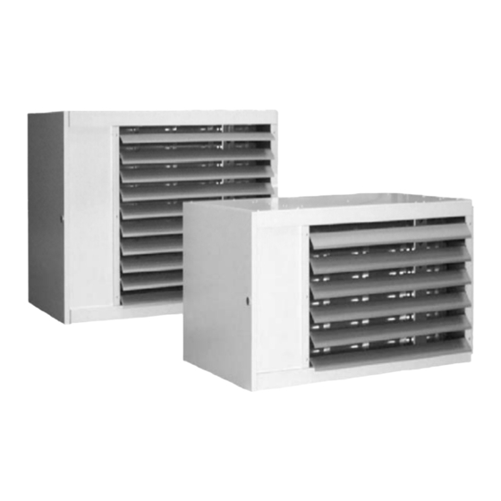
2- TECHNICAL SPECIFICATIONS OF ACG UNIT HEATERS Axial Fan. ACGH Model The ACGH unit heaters are equipped with an axial fan. They are intended for direct blowing and are equipped, as standard, with a double deflection grille. 2-1 Performance of ACGH helical gas unit heaters TYPES ACG16H ACG20H ACG26H ACG28H ACG35H ACG36H ACG45H ACG55H ACG75H ACG95H Calorific output... - Page 6 Vertical model ACGV ACGV destratificators are equipped with an axial fan. They are intended for direct vertical blowing and are equipped with a double deflection grille. They are specially suitable for direct blowing into corridors and offer the special feature of both heating and destratifying. 2-2 Performance of the ACGV gas destratificator TYPES ACG26V...
- Page 7 Overall dimensions of the ACGV models Types ACG26V ACG28V ACG36V ACG45V ACG55V ACG75V ACG95V 1040 1 040 1 040 1 120 1 120 1075 134.5 134.5 134.5 149.5 149.5 ——– Ø F 80/125 80/125 80/125 100 / 100 Ø Air Ø...
-
Page 8: Performance Of Acgc Centrifugal Gas Unit Heaters
Centrifugal model. ACGC ACGC unit heaters are equipped with a centrifugal fan and are supplied as standard with an air case (assembly p. 9). They are intended for blowing or taking air from a sheath network. Mixture dampers and a filter can be incorporated on the air case. - Page 9 Flow/pressure curves 1 400 1 600 1 800 2 000 2 200 2 400 2 600 2 800 3 000 M ∆ 41°C ∆ 36°C ∆ 32°C ∆ 29°C ACG20C ∆ 42°C ∆ 37°C ∆ 34°C ACG28C ACG35C ∆ 36°C ∆...
- Page 10 3– MOUNTING OF UNIT HEATERS (See instructions supplied with the consoles) 3-1 Installation recommandations For good functionnning and the security of devices it’s necessary to respect the munimum installation distances (see the schema below). 700 mini mini mini 3-2 Rotating console for IPN adjustable for ACGH 16/20/26/28/35/36/45/55 Caution: make sure of the strength of the bracket ACG16 H ACG20H...
- Page 11 3-3 Wall mounted console for ACGH 16/20/26/28/35/36/45/55/75/95. Caution: make sure that the bracket is strong enough ACG75H ACG95H Connection Dim A (mm) Dim B (mm) Dim C (mm) Dim D (mm) The COAT kit is a wall-fixing console for gas unit heaters ACGH 16/20/26/28/35/36/45/55/75/95. Assembly: See instructions supplied with the consoles.
-
Page 12: Electrical Wiring
4- ELECTRICAL WIRING 4-1 Electrical schematics of the gas heaters ACGH ACGC Phase/ brown Neutral/ blue Earth/ green- yellow Pilot/ black 4-2 Electrical schematics of centrifugal gas air heaters ACG75 Phase/ brown Neutral/ blue Earth/ green- yellow Pilot/ black... - Page 13 4-3 Electrical schematics for the 2 stages gas air heaters and ACGV Phase/ brown Neutral/ blue Earth/ green- yellow Pilot/ black Blowing fan Smoke extractor Pilot wire receiver Burner air pressure switch Limit Excess heat airstat with manual reset Ionisation sensor Fan triggering airstat Ignition electrode Burner regulation airstat...
-
Page 14: Basic Connection Schematic With Pilot Wire Thermostat
4-4 Basic connection schematic with pilot wire thermostat Connection of the unit heater :A : Neutral (blue) - B: Phase (brown) - D: pilot wire (black) - C: Earth ( green/ 1 - Switch off proximity items 2 - Unit heaters 4 –... - Page 15 Clock programmable. Connecting the unit heater : A : Neutral (blue) - B: Phase (brown) - C: Earth ( green/yellow) ACG gas unit heaters are equipped as standard with a receiver which enables the AIRCALO regulator to be connected directly.
-
Page 16: Connecting To The Unit Heater
5– CONNECTING THE EVACUATION CONDUITS 5-1 Evacuation conduit accessories for ACG 20/28/35 Concentric telescopic extension Concentric horizontal cup with finishing flap Concentric roof cup Chimney outlet with moulding Sealed length of 250/500/1000 mm Concentric length of 500/1000 mm Sealed elbow at 45° or 90° Concentric elbow at 45°... - Page 17 5-4 Wall mounted concentric cup connection - C12 – for ACGH and ACGC unit heaters ( II ) C12 – for ACGH and ACGC ( I ) C12 - for ACGH and ACGC 20/28/35 45/55/75/95 The connections for fuel air inlet and The connections of the combustion air inlet evacuation of smoke are made horizontally at and the smoke evacuation are to be...
- Page 18 5-6 Connection to outlet - B22 – for ACGC, ACGH unit heaters and ACGV destratificator (V) B22 - for ACGH and ACGC (VI) B22 - for ACGV 28/35/55/75/95 20/28/35/45/55/75/95 The combustion air is taken directly in the The combustion air is taken directly in the room smoke evacuation...
-
Page 19: Gas Circuit
6- GAS CIRCUIT 6-1 Changing gas The unit heaters are equipped with atmospheric gas torch burners, permitting the use of Natural gas G20, Natural gas G25 and Propane. The combustion ports are engineered so as to ensure very good stability of the flame without separation or return towards the injectors. - Page 20 6-2 Valve adjustment table single speed Adjustment for G20 Adjustment for G25 Adjustment for G31 Types Regulator Gas ramp Washer Regulator Gas ramp Washer Regulator Gas ramp Washer pressure injectors extractor pressure injectors extractor pressure injectors extractor ACG16 9 mbar 4 x AL 1.90 12 mbar 4 x AL 1.90...
-
Page 21: Gas Connection
7- GAS CONNECTION A precise engineering study must be carried out on the diameters of the piping depending on the nature of the gas flow and the length of the piping. Make sure that the pressure drops in the piping do not exceed 5 % of the supply pressure. The gas connections must be carried out in conformity with the requirements concerning interior installations regardless of the type of gas. -
Page 22: Bill Of Material
8-2 Bill of material Detail of RFP card Detail of connections ACG 20 / 28 / 35 ACG 45 / 55 / 75 / 95 Spare parts part number Description ACG20 ACG28 ACG35 ACG45 ACG55 ACG75 ACG95 Smoke outlet ATE131 ATE131 ATE131 ATE004... -
Page 23: Maintenance
9-MAINTENANCE Correct and regular use and maintenance of the unit heater will determine rational and efficient operation, minimum consumption as well as long life. The maintenance must be done with the device cold, with the gas and electricity supplies cut off. These service visits must be carried out by a qualified professional person Parts Maintenance operations... -
Page 24: Trouble Shooting
11- TROUBLESHOOTING In case of problems, make sure that the conditions required prior to operating the unit heater are present. If the control box is in the safety position (with the burner defect indicator lamp lighted up), reset it. CAUTION : All electrical or mechanical operations must be carried out when the electrical supply is cut off and the gas supply is closed.
Need help?
Do you have a question about the ACGH 20 and is the answer not in the manual?
Questions and answers