
Summary of Contents for Varex Imaging Claymount AmpMC 3-field Series
- Page 1 AmpMC 3-field Series Intended Part numbers as listed in Table 1 0120 Technical Manual TM20514-10, Revision: 3.0 www.vareximaging.com...
-
Page 2: Table Of Contents
Table of Contents Table of Figures ............................3 Introduction ...........................4 Contact information ......................4 Declaration of Conformance ....................4 Symbols used in this document ...................4 Abbreviations ........................5 General warnings, cautions and notes ................5 Supplied components ......................5 Accessories ..........................6 Product description ........................7 Intended use ........................7 Description of the device ......................7 Principle of operation ......................7 Classifications ........................7... -
Page 3: Table Of Figures
Although this guide is prepared with utmost care, Varex Imaging Nederland B.V. assumes no responsibility for errors or omissions. Varex Imaging Nederland B.V. cannot be held accountable for damages of any nature arising from the use, and / or use of any options other than original Varex Imaging Nederland B.V. products. -
Page 4: Introduction
Serial number: Declaration of Conformance Varex Imaging Nederland B.V. hereby declares that this product is in conformity with the essential requirements and provisions as set forth in European Union Council Directive 93/42/EEC concerning medical devices (revision 2007-09-27). See the included Declaration document. -
Page 5: Abbreviations
Please ensure that the contents of the package you received is intact and that there are no traces of moisture or visual damages. Otherwise, you should immediately contact your distributor or Varex Imaging Nederland B.V.. The package contains the following components: Amount... -
Page 6: Accessories
Accessories The following accessories can be ordered separately. Description Purpose Extension cables, for use between SolidStateMC and AmpMC EXTENSION CABLE, SSMC, 2.5M EXTENSION CABLE, SSMC, 5M EXTENSION CABLE, SSMC, 10M To connect all 3-field SolidStateMC models to AmpMC EXTENSION CABLE, SSMC, 45FT model 1001 + 1006 + 1008. -
Page 7: Product Description
2. Product description Intended use The device is intended to be used in medical diagnostic applications with restrictions to human diagnostics. The device is intended to be used as accessory of an X-ray system in a professional healthcare facility environment. The device is intended to amplify and integrate the output signal of a SolidStateMC to the AEC-module of an X-ray generator. -
Page 8: Restrictions On Use
Restrictions on use The AmpMC can only be used in combination with a SolidStateMC and in a Radiography X-ray system that complies with the IEC60601-1 standard, applicable at date of manufacture. The supply lines must be limited / fused to 15W max. or the AmpMC must be mounted inside a fire enclosure. -
Page 9: Specifications
Specifications Description Reference Exposure time range ≤ 4 ms to 5 s. Fine-tuning with potentiometer - 60% to + 150% Input range 0.1 – 12.000 nA. +/- 12 VDC +/-5% to +/- 15 VDC +/-5% Operating voltage Measured at the AmpMC. 0.1 A @ + 12 VDC 0.1 A @ - 12 VDC Supply current 0.1 A @ + 15 VDC 0.1 A @ - 15 VDC... -
Page 10: Installation
3. Installation NOTE: Allow system to level with room temperature before installation. Installation requirements WARNING: Installation and initial operation may only be carried out by an expert who has been trained in the field of medical diagnostic X-ray equipment. WARNING: Modifications to the product are not allowed. -
Page 11: Generator Switch Off Check
Generator Switch off check Without a patient or phantom, a radiation exposure with 80kV, 100mA, 21 s is released. The Automatic Exposure Control must terminate the exposure in less than 100 ms. Necessary recurrent testing WARNING: Before granting the Automatic Exposure Control for use on patients, check the functionality of all AEC fields with a phantom. -
Page 12: Mains Isolation
4. Mains isolation Secundary AmpMC SolidStateMC circuit Figure 1 Means of protection The AmpMC always needs to be connected to an X-ray system that complies with the required regulations and standards. 5. Service, maintenance and cleaning Refer service to a qualified service technician only. AmpMC models do not require maintenance and will last during the lifetime of the X-ray system. -
Page 13: Device Data
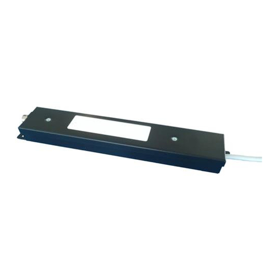
6. Device Data Figure 2 Image of an AmpMC 1001, 1006, 1008, – 3-field integrating amplifier Figure 3 Lay-out Mechanical Figure 4 DIL switch location Technical Manual: TM20514-10 AmpMC 3-field Series Revision: 3.0 13/24 www.vareximaging.com Date of release: 2019-01-09... -
Page 14: Generator Interface Connections
Generator Interface connections Pin Numbers for Designation (Standard) Sub D Connector 9 pole male 10 pins Not connected Field II select Field I select Reset / exposure select Ramp output signal Field III select - 12 VDC to - 15 VDC + 12 VDC to + 15 VDC GND (Shield) Not connected... -
Page 15: Ramp Polarity Settings
Ramp Polarity settings The polarity of the output voltage ramp is selected by means of switches 1 and 2 of DIL-switch S2. Setting S2.1 S2.2 Ramp polarity code Output open Positive ramp Standard version Negative ramp Output Shorted, not allowed Inputs reset / exposure settings The selection of active L or active H mode for reset / exposure input is performed by means of switch 3 on DIL-switch S2. -
Page 16: Plug Pinout Reset / Ramp Selection
Plug pinout reset / ramp selection The plug pinout on the SUB-D plug for reset and ramp may be changed by means of DIL-switch S3. Setting S3.1 S3.2 S3.3 S3.4 Ramp Reset code Pin 5 Pin 4 Standard version Pin 4 Pin 5 Assignment of measuring fields to the signal inputs The plug pinout on the SUB-D plug for the measuring field selection may be assigned by means of... -
Page 17: Disposal, Esd And Emc Compatibility
8. Disposal, ESD and EMC compatibility Disposal This device contains substances that can be hazardous to the environment and care should be taken when disposed of. The device is marked with the following symbol: Follow local regulations regarding disposal of devices that contain electronic parts. WARNING: The device contains sensitive electronics. -
Page 18: Allowances
Allowances No allowances from IEC60601-1-2:2014 are used. Precautions Precautions to be taken to prevent adverse events to the PATIENT and the OPERATOR due to Electromagnetic Disturbances are listed in the column “Electromagnetic environment – guidance” in the tables below. Emissions Compliance Guidance and manufacturer’s declaration –... - Page 19 Guidance and manufacturer’s declaration – Electromagnetic immunity – Compliance Test Levels for ENCLOSURE PORT IMMUNITY to RF wireless communications equipment Test Maximum MMUNITY Band Service Modulation Distance frequency power TEST LEVEL (MHz) (MHz) (V/m) Pulse modulation 380 – 390 TETRA 400 18 Hz GMRS 460;...
- Page 20 Guidance and manufacturer’s declaration – Electromagnetic immunity – Power and Signal PORTs The AmpMC 3-field is intended for use in the Electromagnetic environment specified below. The customer or user of the AmpMC 3-field should assure that it is used in such an environment. Immunity test Compliance Test level Electromagnetic environment - guidance...
-
Page 21: Product Label And Symbols On The Device
9. Product label and symbols on the device Product label The product label can be found at the top side of the AmpMC. Symbols on the device Symbol Explanation Manufacturer. Date of manufacture. Catalogue number. Serial number. CE-mark directive 93/42/EC; conformity assessment by notified body 0120. 0120 Follow the instructions for use. - Page 22 Technical Manual: TM20514-10 AmpMC 3-field Series Revision: 3.0 22/24 www.vareximaging.com Date of release: 2019-01-09...
-
Page 23: All Rights Reserved
+63 2 8076 472 China.CNC@vareximaging.com Philippines.CNC@vareximaging.com © 2018 by Varex Imaging Nederland B.V. All Rights reserved. No part of this document may be reproduced or transmitted in any form or by any means, electronic, mechanical, photocopying, recording, or otherwise, without prior written permission of Varex Imaging Nederland B.V. - Page 24 Technical Manual: TM20514-10 AmpMC 3-field Series Revision: 3.0 24/24 www.vareximaging.com Date of release: 2019-01-09...
Need help?
Do you have a question about the Claymount AmpMC 3-field Series and is the answer not in the manual?
Questions and answers