Table of Contents
Advertisement
Advertisement
Table of Contents

Summary of Contents for ZANDER HDK 50/100
- Page 1 High Pressure Dryer 50/100-600/350 Operating Instructions Issue 05-2005/EN...
- Page 2 Declaration of Conformity ZANDER Aufbereitungstechnik GmbH & CO KG Im Teelbruch 118 D – 45219 Essen Kettwig hereby declares with sole responsibility, that the products high pressure dryer series HDK 18/25 to 600/420 assembly type: assembly acc. to Art. 3 No. 2.2,...
- Page 5 Machine passport Type designation Order no. Project no. Build no. Vessel no. Vessel no. Year of manufacture 2005 Issue date of these operating instructions 2005-05 EN It is the responsibility of the owner, to enter for the first time any appliance data not stated above, to keep these appliance data up to date.
-
Page 7: Table Of Contents
Table of contents General information....................9 Manufacturer's details......................... 9 Details on the dryer........................10 About these operating instructions................... 11 For your own safety....................12 Signs, instruction plates and danger zones at the dryer............12 Intended use of the dryer......................14 General safety notes......................... 14 Safety notes on specific operating phases................ - Page 8 Emergency shutdown....................... 43 Depressurising and shutting down the dryer................43 If work is to be carried out on the electrical system..............43 Restart ............................44 Maintenance and repair of the dryer..............45 Notes on maintenance......................45 Regular maintenance intervals....................46 Daily maintenance tasks......................
-
Page 9: General Information
General information General information Manufacturer's details Name and address Zander Aufbereitungstechnik GmbH & Co. KG Im Teelbruch 118 Postfach 185524 45219 Essen 45205 Essen Telephone ++49 (0)2054/934-0 Telefax ++49 (0)2054/934-164 Internet: www.zander.de E-mail: info@zander.de Service and orders Service and spare part order... -
Page 10: Details On The Dryer
Details on the dryer Details on the dryer Standard equipment Dryer, comprising 2 vessels, filled with desiccant 1 upstream filter 1 downstream filter Piping and muffler Control system Associated documents Operating instructions (present) Technical documentation (see annex) Circuit diagrams (see separate document) Warranty notes In the following cases, the warranty shall be void: If aggressive media in the compressed air and in the environment cause... -
Page 11: About These Operating Instructions
General information About these operating instructions These operating instructions contain basic information on the safe useof the dryer. Characters and symbols used ► Work steps that you have to carry out in the sequence stated are marked by black triangles. Lists are marked by a small box. -
Page 12: For Your Own Safety
Signs, instruction plates and danger zones at the dryer For your own safety The dryer has been built in accordance with the state of the art and the recognized technical safety regulations. Nevertheless, there is a risk of personal injury and damage to property when the dryer is used, if it is operated by non-qualified personnel, not used within its intended design specifications, is repaired or maintained incorrectly. - Page 13 For your own safety Hazard areas on the dryer Hazard caused by electrical voltage Hazard caused by overpressure Hazard caused by sudden air ejection during expansion Symbol in operating Hazard area instructions Warning against hazardous electrical voltage Different parts of the dryer carry electrical current. These parts may be connected, opened, and maintained by authorized specialist personnel only.
-
Page 14: Intended Use Of The Dryer
Intended use of the dryer Intended use of the dryer The dryer is exclusively intended for drying compressed air. Depending on defined input conditions, it dries compressed air for industrial use. The dryer is designed for compressed air, which is free from aggressive water, oil, and solid matter constituents. -
Page 15: Safety Notes On Specific Operating Phases
For your own safety Safety notes on specific operating phases Transportation and siting Only use suitable and technically perfect lifting gear with a sufficient carrying capacity. Carefully secure the dryer during transportation. Start-up Warning against sudden air ejection! During expansion the pressure is released suddenly through the muffler: A loud cracking noise occurs which can injure your hearing. - Page 16 Safety notes on specific operating phases Only operate the dryer within the permissible limits (see type plate). By operating the dryer in conditions that go beyond the defined values, the dryer is subjected to loads for which it has not been designed. This may cause functional defects.
- Page 17 For your own safety Only use replacement parts that are suitable for the relevant function and meet the technical requirements stipulated by the manufacturer. This is always the case, if you use original replacement parts only. Disassembly and disposal Hazard due to a sudden release of pressure! Never remove any parts of the dryer, or manipulate the same in any way, for as long as the plant is still pressurised! A sudden escape of pressure may cause serious injuries.
-
Page 18: Technical Product Description
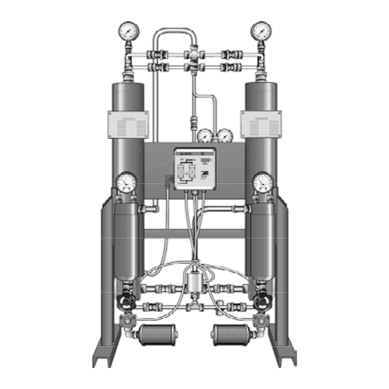
Summary drawing Technical product description Summary drawing Front view Vessel pressure gauge Manometer Pressure reducer with manometer On/Off-Switch Control cabinet Power supply Differential pressure connector gauge Compressed air outlet Compressed air inlet Downstream filter Upstream filter Valves Hand drain Muffler HDK350_EN_01_2005-05-10... -
Page 19: Function Description
Technical product description Function description The dryer dries the compressed air supplied by the compressor and makes it available for industrial use. Upstream filters clean the compressed air and remove dust, dirt, oil, and water droplets, before the compressed air reaches the dryer. Thus, an upstream filter is also used for extending the service life of the drying agent. -
Page 20: Available Options
Available options Pressure build-up phase After dehumidification the pressure in the regenerated hollow section vessel is built up to operating pressure, so that the switchover from regeneration to adsorption can take place at operating pressure level. Standby phase (only with the dewpoint-sensing control option) When in standby phase, the fully regenerated vessel is ready for absorption operation. - Page 21 Technical product description Freezing of valves, cocks, flaps, and other components at low temperatures Therefore, a planned outside installation must always be discussed in advance with the manufacturer to allow specific technical design measures to be provided for the installation location. Auxiliary heater For installation sites with temperatures under +1 ºC (33,8 °F), the wet side of the dryer must be equipped with an auxiliary heater to prevent valves, cocks, flaps,...
- Page 22 Available options Paint compatible design Paint shop plants impose particularly stringent requirements with regard to the cleanliness of the compressed air, as already the minutest contaminations can reduce the quality of the paint finish. Even minute quantities of oil and grease containing foreign materials or solvents —...
-
Page 23: Transportation, Installation And Storage
Transportation, installation and storage Transportation, installation and storage Danger due to incorrect transportation! The dryer must be transported by authorized and qualified specialist personnel only. During transportation all applicable national regulations for accident prevention must be complied with. Otherwise there is a risk of personal injury. -
Page 24: Transporting And Installing The Dryer
Transporting and installing the dryer Transporting and installing the dryer Requirements for the installation site The conditions at the installation site have a large influence on the functional capability of the dryer and the service life of the drying agent. In order to ensure a mode of operation, which is as continuous as possible, and low maintenance, the installation site must meet the following requirements: The installation site must be located within a building - protected against... -
Page 25: Installing And Anchoring
Transportation, installation and storage ► Secure the dryer on the lifting or forklift truck against sliding movements. ► Transport the dryer to its installation site. Dryer on transportation pallet Installing and anchoring Installing ► Remove the packaging of the dryer. ►... -
Page 26: Storing The Dryer
Storing the dryer Anchoring the dryer The upright stand profiles of the dryer are provided with pre-drilled anchorage bores. ► Use suitable attachment material to anchor the dryer to the floor (see figure). ► In the case of vibrating floors: place the dryer on suitable vibration dampers. - Page 27 Transportation, installation and storage Note: If you wish to take the dryer back into service after an extended period of storage, please proceed as described for its first commissioning and start-up (see page 37). Store drying agents ► Do not store drying agents in the open air. ►...
-
Page 28: Installation
Preconditions for installation Installation Only authorized and qualified specialist personnel may carry out work on pipes and electrical systems. As soon as the dryer has been set up at its installation location, you can install the compressed air infeed and outlet lines make the electrical connections. Preconditions for installation For a correct installation the following preconditions must be met on the part of the owner. -
Page 29: Installing The Electrical Connection
Installation All piping must be free from any stress and tension whatever! Pipes subject to stress may burst due to the load placed on them during operation. This may cause damage to property and personal injury. ► Use steel pipes to connect the dryer to the compressed air system. The following figure shows an installation example. - Page 30 Installing the electrical connection ► Ensure that the cross-section of the electrical supply cable corresponds to the power rating of the dryer and the electrical voltage provided by the customer. ► Make the electrical supply cable to the dryer voltage-free. ►...
- Page 31 Installation For operation monitoring system (optional) Operators have the option to connect the dryer to a fault signalling system, connecting the respective line to a potential-free operation signalling contact. With this option, the following statuses and events can for example be transmitted to a remote control room: Dryer on (contact made) Power supply disconnected (no contact)
-
Page 32: Start-Up
Requirements for initial start-up Start-up Warning! The dryer must be taken into operation by trained personnel only! Untrained personnel does not have the required knowledge. Such personnel might cause serious faults. Note: You can order the initial commissioning and start-up from the manufacturer and have your personnel trained by the manufacturer. -
Page 33: Setting Times Of The Operating Phases
Start-up Setting times of the operating phases In its standard version the dryer is delivered with a time-dependent control system. The phase sequence occurs in a fixed cycle. With the optional dewpoint-sensing control, the dryer can also be operated at variable cycles (depending on the dewpoint). - Page 34 Overview of operating and control elements Display panel The display panel at the switchbox is equipped with LEDs (light emitting diodes) and a digital display, indicating the operating status of the dryer: Display panel at the switchbox LED Power (1) LED is on when dryer is switched on.
- Page 35 Start-up Digital display (3) The digital display shows the individual programme steps and the respective remaining time. For details regarding the sequence of the individual processing steps and their duration, please refer to the logic control diagram, page 68. Display Explanation Default display: The figure to the left indicates the current processing step;...
-
Page 36: Emergency Shutdown
Emergency shutdown During adsorption the pressure gauge should indicate the nominal operating overpressure. During regeneration the indication of the pressure gauge on the regenerating vessel should decrease in the expansion phase from operating overpressure to — 0 bar overpressure, indicate an overpressure of 0 bar in the dehumidification phase. —... - Page 37 Start-up Only operate the dryer within the permissible limits. By operating the dryer in conditions for which it has not been designed, functional faults may be caused. Check the dryer regularly for externally visible damage and defects. Any changes, even in its operating behaviour, must be reported immediately to the competent office or person.
- Page 38 Start up dryer Note: Depending on the pressure dew point to be achieved, we recommend to operate the dryer at first start-up without compressed air consumption: for at least 4 hours at a pressure dew point of –25 to –40 °C or for approx.
-
Page 39: Changing Cycle Mode (Optional)
Start-up ► Repeat the start-up procedure. Changing cycle mode (optional) When can I change cycle mode? If the dryer has been successfully commissioned and is equipped with one of the following options: regeneration gas return for compressor synchronisation or dewpoint-sensing control it can be set to economy cycle mode. - Page 40 Changing cycle mode (optional) How do I change cycle mode? ► Wait until the dryer has reached the pressure build-up phase (phase prior to switchover). One LED for Adsorption B1/B2 is on in the flow diagram. ► Set the ON/OFF switch to position II. ON/OFF switch The programme continues the cycle.
-
Page 41: Monitoring Dryer Operation
Monitoring dryer operation Monitoring dryer operation The dryer operates fully automatically. However, you should carry out the regular checks described in the Chapter Maintenance and repair of the dryer. Warning against sudden air ejection! During expansion the pressure is released suddenly through the muffler: A loud cracking noise occurs which can injure your hearing. -
Page 42: Shutdown And Restart Dryer
Mains power failure Shutdown and restart dryer In the following cases, the dryer must be fully shut down and depressurised: In the event of an emergency or malfunction For maintenance work For dismantling Risk of injury from escaping compressed air! Never remove any parts of the dryer, or manipulate the same in any way, as long as the unit is pressurised! Suddenly escaping compressed air might cause serious injuries. -
Page 43: Emergency Shutdown
Shutdown and restart dryer Emergency shutdown In any emergency proceed as described in the next section. Depressurising and shutting down the dryer In order to make the dryer safe, follow the instructions in the next three sections: Disconnect dryer from compressed air system ►... -
Page 44: Restart
Restart Restart Depending on the fittings installed by the operator and the actual pressure conditions, the unit might have to be restarted at operating pressure. The following general rules apply: When switched off, the dryer is blocked in the main flow direction. The pressure in the vessel drops (provided that the compressed air outlet valve provided by the operator is opened), if compressed air can escape to the compressed air system,... -
Page 45: Maintenance And Repair Of The Dryer
Maintenance and repair of the dryer Maintenance and repair of the dryer In order to allow maintenance work on the dryer to be carried out efficiently and without danger for maintenance personnel, you should comply with the following instructions. Notes on maintenance Warning! Maintenance tasks may be carried out only by authorized and qualified specialist personnel, and only with the plant in a switched off and... -
Page 46: Regular Maintenance Intervals
Regular maintenance intervals Regular maintenance intervals Note: If a vessel has been depressurised, e.g. after completion of the expansion phase, and the pressure remains above 0 bar, the vessel is pressurised by what is known as ram pressure. This might be due to blockage at the muffler(s), contamination of the dust sieves, spent drying agent. -
Page 47: Daily Maintenance Tasks
Maintenance and repair of the dryer Danger! There is a very considerable risk of personal injury, when carrying out work on the activated and pressurised dryer. Before commencing any maintenance tasks always shut down the dryer as described on page 43, Depressurising and shutting down the dryer! Warning against electrical voltage! Only qualified specialist personnel may carry out work on the electrical system! -
Page 48: Weekly Maintenance Tasks
Weekly maintenance tasks Weekly maintenance tasks Check differential pressure on the filters ► Check the differential pressure on the pressure gauge of the filter. The differential pressure should be 0.6-0.8 bar max. If the differential pressure exceeds 0.6-0.8 bar, we recommend that you replace the filter element (see page 48). - Page 49 Maintenance and repair of the dryer Renew mufflers The dryer is equipped with mufflers. If a muffler becomes blocked, a dam pressure is generated which in extreme cases may cause the muffler to burst. Hazard caused by blocked muffler! Blocked mufflers can cause a dangerous overpressure to build up which may cause the mufflers to burst.
- Page 50 Maintenance work to be completed every 12 months Recalibration of dewpoint sensor (optional) In order to ensure accurate dew- point measuring, we recommend recalibrating the dewpoint sensor at least every 12 months. The recalibration must be carried out by the manufacturer. This period depends however on the actual application and might thus be extended accordingly.
- Page 51 Maintenance and repair of the dryer ► Loosen the screw at the adapter (1) and disconnect signal cable with the adapter and seal. ► Remove dewpoint sensor from the sensor cell (3) by turning the nut (2). ► Take the new dewpoint sensor (2) from the box, remove the protective caps (4, 5) and screw it into the sensor chamber (3).
-
Page 52: Maintenance Work To Be Completed Every 48 Months
Maintenance work to be completed every 48 months Maintenance work to be completed every 48 months To complete the following maintenance tasks, you must dismantle the pipe bridges and the vessels. We therefore recommend that you carry out these tasks together. - Page 53 Maintenance and repair of the dryer Wear eye protection and dust mask due to increased dust generation! When emptying the drying agent, increased dust generation may occur. In order to avoid any eye irritations, wear protective goggles! In order to avoid any dust inhalation, wear dust mask! Risk of skidding! If drying agent has been spilt on the floor, there is a risk of skidding caused by the drying agent beads.
- Page 54 Maintenance work to be completed every 48 months Warning! If the dryer is not used within specifications, the drying agent can be contami- nated with pollutants. Always take this into account for the environmentally safe disposal of the drying agent. The waste code numbers of the drying agent can be obtained from the manufacturer (see page 9).
- Page 55 Maintenance and repair of the dryer Note: To achieve an optimum bulk density, we recommend using a "snowstorm" filling pipe available from the manufacturer. ► Otherwise use a rubber hammer to tap regularly against the vessel wall during filling or use a rod to distribute and compact the drying agent through the vessel opening.
-
Page 56: Identify And Eliminate Faults
Summary of faults Identify and eliminate faults The following table provides information on what designatory abbreviations are to be used for the various components. These designations are also found in the technical documentation. Used abbreviation Component B1/B2 Vessel Differential pressure gauge Pressure gauge V1, V2 Main valves... - Page 57 Identify and eliminate faults Fault Possible cause Remedy Dewpoint is not reached Operating pressure too low Increase operating pressure Excessive differential pressure at Check differential pressure at the upstream filter upstream filter; replace filter element, if necessary. Compressed air volume flow too high Reduce compressed air volume flow. Inlet temperature of compressed air Reduce inlet temperature of too high...
- Page 58 Summary of faults Fault Possible cause Remedy No expansion in Valve V7/V8 does not open properly see * chamber Dryer is continuously Valve V7/V8 does not close properly see * bled Valve V1/V2 does not close properly Dryer is bled excessively Valves V1/V2, V3, V4, V5, V6 do not see * close properly Check supply voltage.
-
Page 59: Index
Index Index Design paint compatible ........... 22 Dew point sensor Abbreviation maintenance interval ..........46 components............56 Dewpoint-sensing control ......... 21 Address, manufacturer ..........9 Digital display Adsorption, explanation..........19 explanation ............35 air ejection Documentation, technical ......... 62 hazard ..............13 Dryer Auxiliary heater............ - Page 60 contact..............21 Original replacement parts ......... 17, 45 LEDs Outside installation........... 20 explanation............34 overpressure, hazard ..........13 Liability ..............10 lifting gear ............15, 23 Limits, permissible..........16, 37 Packaging ..............23 Parameters preset ..............10 Machine damage, prevention........12 Personnel qualification ......
- Page 61 Index requirements ............26 Use, safe ..............11 Supply cable, electrical ..........29 Supply lines.............. 28 Switching off............. 42 Variable cycle ............21 symbols, explanation..........13 Vessel pressure gauge maintenance interval ..........46 vibration dampers ............. 26 Target group ............11 Visual inspection............
-
Page 62: Annex With Technical Documentation
Annex with technical documentation This annex comprises the following information and technical documentation: Technical data Replacement and wear parts list Logic control diagram Flow diagram Dimensional drawing HDK350_EN_01_2005-05-10... -
Page 63: Technical Data
Annex with technical documentation Technical data Capacity* Length Height Width Weight Type 100 bar 50/100 1155 80/100 1205 HDK 140/100 1220 HDK 250/100 1350 HDK 400/100 1410 HDK 600/100 1710 250 bar 50/250 1155 80/250 1205 HDK 140/250 1220 HDK 250/250 1350 HDK 400/250 1410... - Page 64 Technical data Type HDK 50/100–600/350 Fluid group (acc. to 97/23/EC) max. operating overpressure 100/250/350 bar min. operating overpressure min. ambient temperature ≥+1 °C (33,8 °F) max. ambient temperature ≤+50 °C (122 °F) Rel. humidity ≤ 60 Noise level : +3 dB (A) relative to free field measurement, 1 m surr.
-
Page 65: Replacement And Wear Parts List
Annex with technical documentation Replacement and wear parts list Items see dimension drawing. Type HDK 100/250/350 bar Item Designation 50/... 80/... 140/... 250/... 1 Vessel 5 Ecosorb IIa 675010025502 6 Molecular screen MS512 675010051201 7 Dust sieve 799020002003 799020003202 2 Upstream filter G3XP G5XP G7XP... - Page 66 Replacement and wear parts list Type HDK 100/250/350 bar Item Designation 50/... 80/... 140/... 250/... Valves 9 Pressure build up valve, Expansion 641400023001 valves, DN 6 10 Main valve DN 12 641400023001 13 Check valve ø 16 620300001629 14 Check valve ø 8 620300000825 15 Check valve ø...
- Page 67 Annex with technical documentation Type HDK 100/250/350 bar Item Designation 400/... 600/... 1 Vessel 5 Ecosorb IIa 675010025502 6 Molecular screen MS512 675010051201 7 Dust sieve 799020003202 2 Upstream filter G7XP G11XP 2.3 Filter element 1140 XP 211010011411 — 2.3 Filter element 2020 XP —...
-
Page 68: Logic Control Diagram
Logic control diagram Logic control diagram Adsorption in B1 and regeneration in B2 HDK350_EN_01_2005-05-10... - Page 69 Annex with technical documentation Regeneration in B1 and adsorption in B2 HDK350_EN_01_2005-05-10...
-
Page 70: Flow Diagram
Flow diagram Flow diagram Item Designation Item Designation Vessel Control cabinet Upstream filter 13, 14, 15 Check valves Downstream filter Pressure reducer Dust sieve Vessel manometer Pressure build up valve Muffler Main valve HDK350_EN_01_2005-05-10... -
Page 71: Dimensional Drawing
Annex with technical documentation Dimensional drawing Type HDK 100/250/350 bar Dimensions (mm) 50/... 80/... 140/... 250/... 400/... 600/... 1155 1205 1220 1350 1410 1710 Connection G 1/2 “ G 1/2 “ G 1/2 “ G 1/2 “ G 3/4 “ G 3/4 “... - Page 72 Dimensional drawing Items Option HDK350_EN_01_2005-05-10...
Need help?
Do you have a question about the HDK 50/100 and is the answer not in the manual?
Questions and answers