
Subscribe to Our Youtube Channel
Summary of Contents for RenewAire GH Series
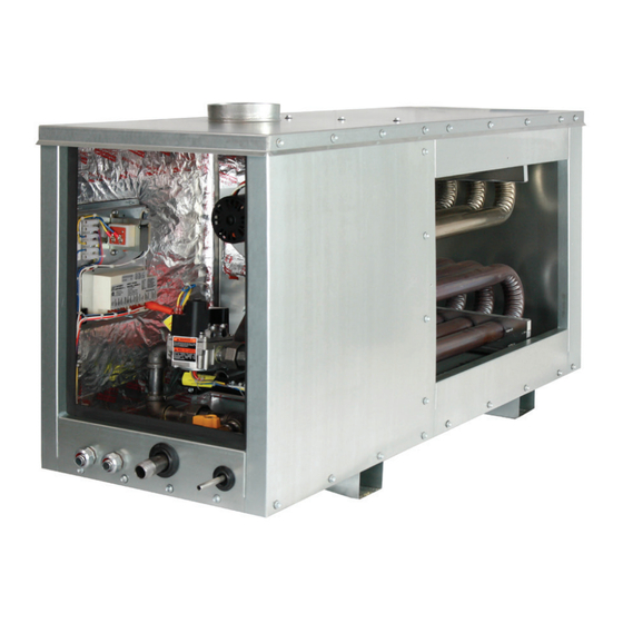
- Page 1 GH SERIES Indirect Gas-Fired Duct Furnace Installation, Operation and Maintenance Manual GH-Series for Indoor and Outdoor Commercial Applications GH Indoor Series shown GH Rooftop Series shown...
- Page 2 ACCESSORY GH-Series Indirect Gas-Fired Duct Furnace WARNING AVERTISSEMENT Ne pas entreposer ni utiliser d’essence ou autre vapeurs ou Do not store or use gasoline or other flammable vapors and liquides inflammable à proximité de cet appareil ou de tout liquids in the vicinity of this or any other appliance. autre appareil.
- Page 3 GH-Series Indirect Gas-Fired Duct Furnace ACCESSORY CAUTION ATTENTION RISQUE DE CHOC ELECTRIQUE OU DE DOMMAGE RISK OF ELECTRIC SHOCK OR EQUIPMENT DAMAGE. D'APPAREIL Whenever electrical wiring is connected, disconnected Chaque fois que le câblage électrique est connecté, décon- or changed, the power supply to the module and module necté...
- Page 4 Record information as shown below. In the unlikely event that factory assistance is ever required, this information will be needed. Locate the RenewAire unit label, found inside the removable panel on the furnace. NOTE: This information is for purposes of identifying the specific furnace. Unit-specific option data can then be obtained, as needed, from the Model Number.
- Page 5 GH-Series Indirect Gas-Fired Duct Furnace ACCESSORY T H I S P A G E I S I N T E N T I O N A L LY L E F T B L A N K . THIS PAGE IS INTENTIONALLY LEFT BLANK 1.800.627.4499...
- Page 6 0.24 0.20 0.16 0.12 0.08 0.04 50/75 0.00 1000 2000 3000 4000 5000 6000 7000 2000 3000 4000 5000 6000 7000 8000 9000 10000 11000 12000 Airflow (CFM) Airflow (CFM) Specifi cations may be subject to change without notice. RENEWAIRE.COM 1.800.627.4499 1.800.627.4499...
- Page 7 OUTDOOR TOP EXHAUST (NO) OUTDOOR TOP EXHAUST (NO) 47.85 47.85 4510 Helgesen Dr. 4510 Helgesen Dr. UNLESS OTHERWISE SPECIFIED, RenewAire LLC UNLESS OTHERWISE SPECIFIED, RenewAire LLC Madison, WI 53718 USA Madison, WI 53718 USA DIMENSIONS ARE IN INCHES. DIMENSIONS ARE IN INCHES.
- Page 8 MODEL GH INDOOR DIMENSIONED DRAWING 1.800.627.4499...
- Page 9 0.24 0.20 0.16 0.12 0.08 0.04 50/75 0.00 1000 2000 3000 4000 5000 6000 7000 2000 3000 4000 5000 6000 7000 8000 9000 10000 11000 12000 Airflow (CFM) Airflow (CFM) Specifi cations may be subject to change without notice. RENEWAIRE.COM 1.800.627.4499 1.800.627.4499...
- Page 10 47.85 47.85 OUTDOOR TOP EXHAUST (NO) TABLE 1 OUTDOOR FRONT EXHAUST (WO) 4510 Helgesen Dr. UNLESS OTHERWISE SPECIFIED, RenewAire LLC Madison, WI 53718 USA DIMENSIONS ARE IN INCHES. TEL: (608) 221-4499 °F Vent Locations TOLERANCES: Min/Max Temperature Rise through Furnace (...
- Page 11 MODEL GH OUTDOOR DIMENSIONED DRAWING 1.800.627.4499...
-
Page 12: Table Of Contents
TABLE OF CONTENTS ACCESSORY GH-Series Indirect Gas-Fired Duct Furnace 1.0 OVERVIEW 7.6 FURNACE INSTALLATION REQUIREMENTS .....49 7.7 INSTALL CONTROL SENSORS ........50 1.1 DESCRIPTION ............17 7.8 INSTALL GAS SUPPLY PIPING ........50 1.2 GAS SUPPLY ............17 7.8.1 Installation of Gas Piping ...........50 1.3 ELECTRICAL SUPPLY ..........17 7.8.2 Determine Gas Supply Requirement ........ - Page 13 TABLE OF CONTENTS GH-Series Indirect Gas-Fired Duct Furnace ACCESSORY TABLE OF ILLUSTRATIONS Figure 1.5.0 Chart of Available Turndown Options by Furnace Model ..........19 Figure 1.5.1 Typical Installation of Indoor Separate Inlet Exhaust Furnace .......... 20 Figure 1.5.2 Typical Installation of Indoor Top Exhaust Furnace ............20 Figure 1.5.3 Typical Installation of Outdoor Top Exhaust Furnace ............
- Page 14 GH-Series Indirect Gas-Fired Duct Furnace INDIRECT GAS-FIRED DUCT FURNACE CONFIGURATION CODE Each RenewAire Indirect Gas-Fired Duct furnace is assigned a 25 digit Model Number. The Model Number can be used to identify the various options as ordered by the customer.
- Page 15 CONFIGURATION CODE GH-Series Indirect Gas-Fired Duct Furnace ACCESSORY DEFINITIONS FOR CONFIGURATION CODE Heater Type: capacity to input capacity. GH—indirect gas-fired duct furnace from 50 MBH up to Elevation: 400 MBH 0-2000 feet (Standard)—furnace burner orifices for Location: operation up to 2000 ft. above sea level. IN—indoor duct furnace 2001-6999 feet (Option)—furnace burner orifices for operation 2001-6999 ft.
- Page 16 CONFIGURATION CODE ACCESSORY GH-Series Indirect Gas-Fired Duct Furnace Air Proving Switch: (Standard) Manual Reset Flame Rollout Switch: (Standard) Air proving switch included for duct mounting upstream Manual reset flame rollout switch included to monitor of the furnace. Prevents operation of the furnace in the presence of burner flame.
-
Page 17: Overview
THESE FURNACES COMPLY WITH ANSI Z83.8 AND CSA 2.6M Gas-Fired Duct Furnace 1.2 GAS SUPPLY RenewAire gas-fired duct furnaces can be ordered with either natural gas or LP gas as a fuel source, not to exceed pressure of 13.5 inches water Column (InWC) [3,359 Pa]. For all furnaces: Natural gas supply pressure must be a minimum of 5 InWC [1244 Pa] and a maximum of 13.5... -
Page 18: Gas Furnace Modulation (Turndown)
Each modulation scheme requires that the gas train be designed for that specific turndown scheme. Modulation of the gas supply typically involves a different gas valve or valves, some upgrade to the controls and a different gas manifold. RenewAire furnaces are available with the following options:... -
Page 19: Figure 1.5.0 Chart Of Available Turndown Options By Furnace Model
INDOOR TOP EXHAUST OUTDOOR FRONT EXHAUST OUTDOOR TOP EXHAUST INDOOR SEPARATED COMBUSTION (SI) OUTDOOR FRONT EXHAUST (WO) MODEL IN-SI MODEL IN-KI RenewAire LLC 4510 Helgesen Dr. MODEL RT-WO MODEL RT-NO UNLESS OTHERWISE SPECIFIED, Madison, WI 53718 USA DIMENSIONS ARE IN INCHES. -
Page 20: Figure 1.5.1 Typical Installation Of Indoor Separate Inlet Exhaust Furnace
GH-Series Indirect Gas-Fired Duct Furnace See figures below for examples of common installation approaches. FIGURE 1.5.1 TYPICAL INSTALLATION OF INDOOR SEPARATE INLET FIGURE 1.5.2 TYPICAL INSTALLATION OF INDOOR TOP EXHAUST FURNACE EXHAUST FURNACE www.renewaire.com (800) 627- 4499 support@renewaire.com www.renewaire.com (800) 627- 4499 support@renewaire.com... -
Page 21: Single And Multiple Furnace Configurations
OVERVIEW GH-Series Indirect Gas-Fired Duct Furnace ACCESSORY 1.6 SINGLE AND MULTIPLE FURNACE CONFIGURATIONS Furnaces may be installed individually or in parallel. ALL FURNACES MUST BE INSTALLED ON THE POSITIVE PRESSURE SIDE OF THE FAN. Refer to the previous page for typical examples of common installation approaches. -
Page 22: Venting
VENTING ACCESSORY GH-Series Indirect Gas-Fired Duct Furnace 2.0 VENTING 2.1 EQUIVALENT LENGTH NOTE: For assis- Vent pipe lengths are given as “equivalent lengths”. When vent pipes are installed, they often tance with vent require that an elbow(s) be installed as part of the vent pipe. Elbows restrict free flow of gases sizing and design, through the vent pipe. -
Page 23: Figure 2.2.0 Indoor Vertical Venting
1 ft. (305mm) horizontal run to allow for condensate drainage FIGURE 2.2.0 INDOOR VERTICAL VENTING 4510 Helgesen Dr. RenewAire LLC UNLESS OTHERWISE SPECIFIED, Madison, WI 53718 USA 1.800.627.4499 DIMENSIONS ARE IN INCHES. TEL: (608) 221-4499... -
Page 24: Figure 2.2.1 Indoor Horizontal Venting
Exterior Wall 4510 Helgesen Dr. RenewAire LLC UNLESS OTHERWISE SPECIFIED, Madison, WI 53718 USA FIGURE 2.2.1 INDOOR HORIZONTAL VENTING DIMENSIONS ARE IN INCHES. TEL: (608) 221-4499 TOLERANCES:... - Page 25 VENTING GH-Series Indirect Gas-Fired Duct Furnace ACCESSORY EACH DUCT FURNACE MUST HAVE ITS OWN INDIVIDUAL VENT PIPE AND TERMINAL. Do not connect vent system from horizontally vented units to other vent systems or a chimney. Through the wall vents shall not terminate over public walkways, or over an area where condensate or vapor could create a nuisance or hazard.
-
Page 26: Figure 2.2.2 Vertical Venting - Separate Combustion
Cleanout Cap (Both Pipes) shown in illustra- tions is supplied by others and field installed. 4510 Helgesen Dr. RenewAire LLC UNLESS OTHERWISE SPECIFIED, Madison, WI 53718 USA DIMENSIONS ARE IN INCHES. TEL: (608) 221-4499 TOLERANCES: FAX: (608) 221-2824... -
Page 27: Outdoor Furnace Venting
FIGURE 2.3.0 OUTDOOR HORIZONTAL VENTING Listed Vent Terminal 48 in. Min. required in some 12 in. Min. jurisdictions 4510 Helgesen Dr. RenewAire LLC UNLESS OTHERWISE SPECIFIED, Madison, WI 53718 USA DIMENSIONS ARE IN INCHES. TEL: (608) 221-4499 TOLERANCES: FAX: (608) 221-2824... -
Page 28: Gas Supply
To facilitate servicing of the unit, installation of a union is recommended. All gas supply and furnace connections must be leak tested prior to placing equipment in service. FIGURE 3.0.0 EXAMPLE OF MULTIPLE FURNACE SUPPLY GAS PIPING www.renewaire.com (800) 627- 4499 support@renewaire.com 1.800.627.4499... -
Page 29: Placement Recommendations
PLACEMENT GH-Series Indirect Gas-Fired Duct Furnace ACCESSORY 4.0 PLACEMENT RECOMMENDATIONS WARNING RISK OF FIRE OR EXPLOSION! Do not install duct furnace where it may be exposed to potentially explosive or flammable vapors! Do not store or use gasoline or other flammable vapors and liquids in the vicinity of this or any furnace. -
Page 30: Figure 5.0.0 Ductwork Configuration Example A
24" MIN TOP VIEW FIGURE 5.0.0 DUCTWORK CONFIGURATION EXAMPLE A RenewAire LLC UNLESS OTHERWISE SPECIFIED, DIMENSIONS ARE IN INCHES. TOLERANCES: TOLL LINEAR 0.015 HOLE SIZE 0.005... -
Page 31: Figure 5.0.2 Ductwork Configuration Example C
REMOVABLE 24" MIN SERVICE PANEL FRONT VIEW FIGURE 5.0.2 DUCTWORK CONFIGURATION EXAMPLE C 4510 Helgesen Dr. RenewAire LLC UNLESS OTHERWISE SPECIFIED, Madison, WI 53718 USA DIMENSIONS ARE IN INCHES. TEL: (608) 221-4499 TOLERANCES: FAX: (608) 221-2824 TOLL FREE: (800) 627-4499 LINEAR 0.015... -
Page 32: Component Technical Data
TECHNICAL DATA ACCESSORY GH-Series Indirect Gas-Fired Duct Furnace 6.0 COMPONENT TECHNICAL DATA Gas Furnace 50 ‐ 200 MBH 6.1 PERFORMANCE DATA 0.32 0.28 0.24 0.20 0.16 0.12 0.08 0.04 50/75 0.00 1000 2000 3000 4000 5000 6000 7000 Airflow (CFM) FIGURE 6.1.0 50 - 200 MBH TEMPERATURE AND PRESSURE CHART Gas Furnace 250 ‐... -
Page 33: Furnace Size Selection
TECHNICAL DATA GH-Series Indirect Gas-Fired Duct Furnace ACCESSORY 6.2 FURNACE SIZE SELECTION Furnace sizes are specified according to Input MBH. To select the correct furnace size, it is necessary to determine the required heat output in BTU/Hr and then apply the efficiency rating of the furnace to that output to determine the correct furnace size, measured in Input MBH. -
Page 34: Maximum And Minimum Airflows
TECHNICAL DATA ACCESSORY GH-Series Indirect Gas-Fired Duct Furnace 6.3 MAXIMUM AND MINIMUM AIRFLOWS For every duct furnace, there is a range of airflow that must be maintained in order to produce an acceptable ∆T temperature rise and acceptable pressure drop. If the airflow is too low, the resulting temperature rise will be too high. -
Page 35: Dimensional Drawings
TECHNICAL DATA GH-Series Indirect Gas-Fired Duct Furnace ACCESSORY 6.5 DIMENSIONED DRAWINGS FIGURE 6.5.0 DIMENSIONED DRAWINGS OF DUCT FURNACES 1.800.627.4499... -
Page 36: Gas Train Schematics
FIGURE 6.6.0 EXAMPLE OF SINGLE STAGE AND TWO-STAGE GAS TRAIN www.renewaire.com (800) 627- 4499 support@renewaire.com FIGURE 6.6.1 EXAMPLE OF MODULATED GAS TRAIN www.renewaire.com (800) 627- 4499 support@renewaire.com... -
Page 37: Gas Valve Illustrations
GAS TRAIN GH-Series Indirect Gas-Fired Duct Furnace ACCESSORY 6.7 GAS VALVE ILLUSTRATIONS Photographs are typical of valves used. Actual valve models vary by installation. MANUAL SHUTOFF KNOB ELECTRICAL CONNECTION BLOCK GAS ADJUSTMENT SCREW HONEYWELL 1-STAGE VALVE GAS ADJUSTMENT SCREWS MANUAL SHUTOFF ELECTRICAL CONNECTION SWITCH BLOCK... -
Page 38: Figure 6.7.2 Modulating Gas Valves (Typical)
GAS TRAIN ACCESSORY GH-Series Indirect Gas-Fired Duct Furnace ELECTRICAL CONNECTIONS LOW FIRE ADJUSTING SCREW (UNDER PLASTIC CAP) MAXITROL M SERIES MODULATING VALVE ELECTRICAL CONNECTION BLOCK BUTTON 2 (LOW FIRE) BUTTON 1 (HIGH FIRE) DIP SWITCHES MAXITROL EXA SERIES MODULATING VALVE FIGURE 6.7.2 MODULATING GAS VALVES (TYPICAL) 1.800.627.4499... -
Page 39: Electrical Data
24 VAC transformer or an external supplied 24 VAC transformer. IMPORTANT If external controls are to be powered by the RenewAire ERV low voltage 24VAC transformer or external supplied 24 VAC transformer then follow the requirements for those transformers regarding wire length, wire gauge, and power draw. -
Page 40: Electrical Schematics
ELECTRICAL ACCESSORY GH-Series Indirect Gas-Fired Duct Furnace 6.9 ELECTRICAL SCHEMATICS NOTE: Furnace-specific wiring schematics are provided with each unit and can be found in the document package shipped with the unit. 115 VAC DRAFT INDUCER IGNITION CONTROL LINE 40VA Aux. High ROLL OUT ROLL OUT CAFS... -
Page 41: Figure 6.9.1 Control Wiring, 2 Stage Furnace
ELECTRICAL GH-Series Indirect Gas-Fired Duct Furnace ACCESSORY NOTE: Furnace-specific wiring schematics are provided with each unit and can be found in the document package shipped with the unit. 115 VAC DRAFT INDUCER IGNITION CONTROL LINE 40VA Aux. High ROLL OUT ROLL OUT CAFS T' STAT... -
Page 42: Figure 6.9.2 Control Wiring, 5:1 Turndown Furnace, 50-175 Mbh
ELECTRICAL ACCESSORY GH-Series Indirect Gas-Fired Duct Furnace NOTE: Furnace-specific wiring schematics are provided with each unit and can be found in the document package shipped with the unit. Neut 115 VAC DRAFT INDUCER IGNITION CONTROL XFMR 1 WHT (Com) 40 VA Maxitrol SC40 AIR SWITCH -HI... -
Page 43: Figure 6.9.3 Control Wiring, 5:1 Turndown Furnace, 200-400 Mbh
ELECTRICAL GH-Series Indirect Gas-Fired Duct Furnace ACCESSORY NOTE: Furnace-specific wiring schematics are provided with each unit and can be found in the document package shipped with the unit. Neut 115 VAC 240T6T06 Controller SRTN IGNITION CONTROL DRAFT INDUCER XFMR 1 WHT (Com) 40 VA Maxitrol... -
Page 44: Figure 6.9.4 Control Wiring, 10:1 Turndown Furnace, 200-250 Mbh
ELECTRICAL ACCESSORY GH-Series Indirect Gas-Fired Duct Furnace NOTE: Furnace-specific wiring schematics are provided with each unit and can be found in the document package shipped with the unit. 115 VAC 240T6T06 SRTN IGNITION CONTROL 7062-5903 SC30-SM2AN DRAFT INDUCER XFMR 1 WHT (Com) 40 VA ROLL OUT... -
Page 45: Figure 6.9.5 Control Wiring, 10:1 Turndown Furnace, 300-400 Mbh
ELECTRICAL GH-Series Indirect Gas-Fired Duct Furnace ACCESSORY NOTE: Furnace-specific wiring schematics are provided with each unit and can be found in the document package shipped with the unit. 115 VAC 240T6T06 SRTN IGNITION CONTROL 7062-5903 SC30-SM2AN DRAFT INDUCER XFMR 1 WHT (Com) 40 VA ROLL OUT... -
Page 46: Figure 6.9.6 Furnace Control Wiring Schematic-Analog
ELECTRICAL ACCESSORY GH-Series Indirect Gas-Fired Duct Furnace ANALOG 0-10Vdc DUCT THERMOSTAT WITH EXTERNAL SAFETY INTERLOCKS FOR MODULATING FURNACE SENSOR A SENSOR A 0-10Vdc Analog Input MOD 1 Polarity Sensitive Maxitrol Signal Conditioner OUTPUT OUTPUT REMOVE RELAY 1 FACTORY JUMPER EXTERNAL POWER 24VAC SOURCE REQUIRED. -
Page 47: Figure 6.9.8 Furnace Control Wiring Schematic-External Safety Interlocks
ELECTRICAL GH-Series Indirect Gas-Fired Duct Furnace ACCESSORY FIELD WIRING FOR EXTERNAL SAFETY INTERLOCKS STAGED FURNACES REMOVE FACTORY JUMPER AUX HIGH TEMP. AIR PROVING LIMIT SWITCH SWITCH FIGURE 6.9.8 FURNACE CONTROL WIRING SCHEMATIC - EXTERNAL SAFETY INTERLOCKS STAGED DUCT THERMOSTAT 2-STAGE 1-STAGE HEATING HEATING... -
Page 48: Furnace Installation
Secure the furnace so that it cannot fall or tip in the event of accident, structural failure or earthquake. RenewAire strongly recommends outdoor units are secured properly to the building structure. -
Page 49: Clearance To Combustibles And Service Clearances
Air Flow Proving Switch Probe Auxiliary High Temperature Limit Switch FIGURE 7.6.0 INSTALLATION EXAMPLE 4510 Helgesen Dr. RenewAire LLC UNLESS OTHERWISE SPECIFIED, Madison, WI 53718 USA DIMENSIONS ARE IN INCHES. TEL: (608) 221-4499 TOLERANCES: FAX: (608) 221-2824 TOLL FREE: (800) 627-4499 LINEAR 0.015... -
Page 50: Install Control Sensors
INSTALLATION ACCESSORY GH-Series Indirect Gas-Fired Duct Furnace 7.7 INSTALL CONTROL SENSORS All required control sensors are shipped loose with the unit. Each control device has a separate installation instruction sheet that is included in the documentation package. Each furnace comes equipped with an air proving switch and airflow probe that are to be field- installed. -
Page 51: Determine Gas Supply Requirement
INSTALLATION GH-Series Indirect Gas-Fired Duct Furnace ACCESSORY IMPORTANT All piping should be clean and free of any foreign material. Foreign material entering the gas train can cause damage. IMPORTANT DO NOT connect the furnace to gas types other than what is specified and DO NOT connect the unit to gas pressures that are outside the pressure range shown on the unit label. -
Page 52: Connect Condensate Drain
TRAP LINE FIGURE 7.9.0 RECOMMENDED DRAIN TRAP CONSTRUCTION DETAIL A SCALE 1 : 6 7.10 MAKE ELECTRICAL CONNECTIONS 201 Raemisch Rd. RenewAire LLC UNLESS OTHERWISE SPECIFIED, Waunakee, WI 53597 USA DIMENSIONS ARE IN INCHES. TEL: (608) 221-4499 TOLERANCES: FAX: (608) 221-2824... -
Page 53: Operating Instructions
START-UP GH-Series Indirect Gas-Fired Duct Furnace ACCESSORY 8.0 OPERATING INSTRUCTIONS A wiring diagram and a Sequence of Operation are provided in the unit information package NOTE: Start-Up for each specific control system provided on the duct furnace. Refer to the documents before is defined as the attempting to place the unit in service. -
Page 54: Failure To Ignite
START-UP ACCESSORY GH-Series Indirect Gas-Fired Duct Furnace 8.5 FAILURE TO IGNITE On the initial start-up, or after the unit has been off for long periods of time, the first ignition trial may be unsuccessful due to need to purge air from the manifold at start-up. If ignition does not occur on the first trial, the gas and spark are shut off by the ignition control and the control then enters an inter-purge period of 15 to 90 seconds, during which time the draft inducer continues to run. -
Page 55: Shutdown After Unit Start-Up
BURNER FLAMES GH-Series Indirect Gas-Fired Duct Furnace ACCESSORY Poorly defined, substantially yellow flames, or flames that appear lazy, indicate poor air supply to burners or excessive burner input. Verify gas supply type and manifold pressure with rating plate information. Poor air supply can be caused by obstructions or blockage in heat exchanger tubes or vent discharge pipe. -
Page 56: Maintenance
MAINTENANCE ACCESSORY GH-Series Indirect Gas-Fired Duct Furnace 9.0 MAINTENANCE Annual maintenance: This duct furnace should be inspected and serviced annually by a qualified service NOTE: It may be agency to assure proper operation. Annual servicing of the furnace is normally performed at the beginning necessary to use of the heating season. -
Page 57: Service Parts
TROUBLESHOOTING GH-Series Indirect Gas-Fired Duct Furnace ACCESSORY 9.3 SERVICE PARTS FIGURE 9.3.0 SERVICE PARTS - STAGED CONTROL www.renewaire.com (800) 627- 4499 support@renewaire.com FIGURE 9.3.1 SERVICE PARTS - MODULATED CONTROL www.renewaire.com (800) 627- 4499 support@renewaire.com 1.800.627.4499... -
Page 58: Troubleshooting
SERVICE PARTS ACCESSORY GH-Series Indirect Gas-Fired Duct Furnace 10.0 TROUBLESHOOTING Any failure of the duct heater to operate properly can be isolated by: Verify that conditions shown in the start-up portion of this manual are correct Follow the Sequence of Operation (SOO) to determine the point of failure. The most important resource for trouble shooting is the Sequence of Operation. -
Page 59: Factory Assistance
RenewAireSupport@RenewAire.com Email: Remember that RenewAire Customer Service can only assist with the products sold by RenewAire and their options, it cannot resolve engineering issues that result from air handling system design by others. 12.0 WARRANTY The RenewAire Indirect Gas-Fired Duct Furnace is covered under the standard RenewAire ERV warranty. - Page 60 About RenewAire For over 30 years, RenewAire has been a pioneer in enhancing indoor air quality (IAQ) in commercial and residential buildings of every size.This is achieved while maximizing sustainability through our fifth-generation, static-plate, enthalpic-core Energy Recovery Ventilators (ERVs) that optimize energy efficiency, lower capital costs via load reduction and decrease operational expenses by minimizing equipment needs, resulting in significant energy savings.
Need help?
Do you have a question about the GH Series and is the answer not in the manual?
Questions and answers