
Related Manuals for Rayco C120R


Summary of Contents for Rayco C120R
- Page 1 C120R OPERATOR · SERVICE · MAINTENANCE · MANUAL RAYCO MANUFACTURING © 2019 - ALL RIGHTS RESERVED PRINTED IN USA INDEX: OSMC120R-19...
- Page 2 CONSTIUENTS ARE KNOWN IN THE STATE OF CALIFORNIA TO CAUSE CANCER AND REPRODUCTIVE HARM. VISIT WWW.P65WARNINGS.CA.GOV NOTICE: Maintenance and Repairs should ONLY be performed by a trained specialists or qualified person. Please contact Rayco Mfg for a listing of approved maintenance facilities in your area.
- Page 3 C120R Operator Service Maintenance Manual Content TABLE OF CONTENTS Forward Safety Operation Specifications Maintenance Troubleshoot Warranty 800.392.2686...
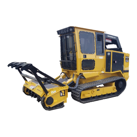
- Page 4 The safety section before operating or performing lubrication, C120R is ideal for those who want a powerful mulcher in a maintenance and repair on this machine. compact chassis. The C120R has an overall width of just...
-
Page 5: Machine Specs
C120R Operator Service Maintenance Manual Foreword Machine Specs GENERAL DATA METRIC Weight With Winch And Mulcher 15,900LBS 7,212KG Length With Mulcher 199.6IN 507CM Height 102IN 259.1CM Width 83.6IN 212.4CM Engine 121HP CAT TIER 4 Fuel Type DIESEL Ground Pressure With Mulcher 5.65PSI... -
Page 6: Serial Numbers Location
Use the below table to record identification numbers and dealer information. Serial Numbers Location Whenever communicating with Rayco or your Rayco dealer, have your machine serial number handy, as it can help pinpoint most exactly what information is needed in caring for your machine. -
Page 7: Identification Numbers
C120R Operator Service Maintenance Manual Serial Number Location & Information Identification Numbers Model Number Serial Number Machine Engine Implement Implement Dealer Information Name Address Dealer Contact Phone Number Hours Sales Parts Service 800.392.2686... -
Page 8: California Proposition
C120R Operator Service Maintenance Manual Safety California Proposition Keep the equipment free from foreign material. Remove debris, oil, tools, and other items from the deck, from walkways, 65 Warning and from steps. Diesel engine exhaust and some of its constituents are known... -
Page 9: Important Safety Information
Rayco, you must use it only if you have accurately evaluated precautions. An accident can often be avoided by recognizing it and found that it threatens no one’s safety. You should potentially hazardous situations before an accident occurs. -
Page 10: General Hazard Information
C120R Operator Service Maintenance Manual Safety General Hazard Information Head protection must conform to ANSI Z89.1 and DO NOT wear under chin strapping while operating or within the operation area of the Horizontal Grinder. Eye protection must conform to ANSI Z87.1 and be the wrap around style. -
Page 11: Fluid Penetration
High pressure oil that is released can cause oil to spray. Fluid penetration can cause serious injury and possible death. Rayco recommends the use of only genuine Rayco Fluid Penetration replacement parts. Use the following guidelines when you... -
Page 12: Crushing Prevention And Cutting Prevention
C120R Operator Service Maintenance Manual Safety Improperly disposing of waste can threaten the environment. Always shut-off the engine and wait for all moving parts, Potentially harmful fluids should be disposed of according belts, fans, rotors, drums, cutting wheels (etc) to come to a to local regulations.Always use leak proof containers when... -
Page 13: Fire Prevention And Explosion Prevention
C120R Operator Service Maintenance Manual Safety Coolant Electrolyte is an acid. Electrolyte can cause personal injury. Do not allow electrolyte to contact the skin or the eyes. Always wear protective glasses for servicing batteries. Wash hands after touching the batteries and connectors. Use of gloves is recommended. -
Page 14: Fire Extinguisher
Repair any lines that are loose or damaged. Leaks can Never check the battery charge by placing a metal object cause fires. Consult your Rayco dealer for repair or for across the terminal posts. Use a voltmeter or a hydrometer. - Page 15 Replacement parts which are authorized by could affect the operator’s performance and concentration. Rayco are the only parts which should be used for repair or Maintain a drug-free work place. replacement on this machine.
-
Page 16: Safety Instructions
Observe all applicable local government regulations when Operation and Maintenance Manual, “Reference Material”. you use this machine. Consult your Rayco dealer in order to obtain copies of the Parking material. The information should be reviewed by every person Park on a level surface. If you must park on a grade, chock that operates the machine. - Page 17 Work Tool options - Attachments Speed of travel – At higher speeds, forces of inertia tend to Only use work tools that are approved by Rayco for use on make the machine less stable. Rayco machines. Refer to the Operation and Maintenance Roughness of terrain or surface –...
- Page 18 C120R Operator Service Maintenance Manual Safety Equipment Lowering with Engine • Keep the terrain in good condition. Stopped a. Remove any large rocks or obstacles. b. Fill any ditches and holes. Before lowering any equipment with the engine stopped, clear the area around the equipment of all personnel. The c.
-
Page 19: Safety Decals
Rayco or polycarbonate front guards that are the applicable requirements for lockout/ tag out procedures, approved by Rayco are available for machines with a cab or and its intent to comply with OSHA regulations. an open canopy. On machines that are equipped with cabs, Lock Out Procedure the windshield should also be closed. -
Page 20: Removal Procedure
C120R Operator Service Maintenance Manual Safety that supplies energy to the equipment. In case of 4. Inform all affected personnel. mechanical energy, a block may be used to stop the 5. Check to see that all affected persons are located in a release of stored energy. - Page 21 C120R Operator Service Maintenance Manual Safety IF WHIPPING or SWAY OCCURS, DO NOT steer. DO NOT apply your brakes and NEVER speed up. Let off the gas pedal and hold the steering wheel in a straight-ahead position. A “combination disturbance” is improper handling, whipping,...
-
Page 22: Operation
C120R Operator Service Maintenance Manual Operation Know Your Machine: General Identification - Exterior 1. Engine Compartment 7. Final Drive 2. Fuel Tank FIll 8. Radiator 3. Hydraulic Tank/DEF Tank Location 9. Rubber Track 4. Cab 10. Winch 5. Work Lights 11. -
Page 23: Cab Interior
C120R Operator Service Maintenance Manual Operation Cab Interior 9. Cup Holder 10. Manual Tube 1. Operator Seat 11. Washer Tank 2. Fire Extinguisher 12. Aux Power Ports 3. Control Panel 13. Slope Indicator 4. Right Joystick 14. Radio 5. Display Panel 15. -
Page 24: Pre-Start Procedure
C120R Operator Service Maintenance Manual Operation Pre-Start Procedure Seat and Seat Belt Inspection Walk-Around Inspection Adjust the seat at the beginning of each work period. Also adjust the seat when you are changing operators. For maximum service life of the machine, make a thorough walk-around inspection. -
Page 25: Rollover Protective Structure (Rops)
See your Rayco dealer for mounting guidelines. Allow a cold engine to warm up at a low idle for at least five • Any alteration that is not specifically authorized by Rayco minutes. To help the hydraulic systems to warm up faster, invalidates the certification for the ROPS/FOPS. -
Page 26: Seat Belt Adjustment
PARKING BRAKE ENGAGED. ENSURE THAT ALL Seat Belt SEAT POSITIONS AND ADJUSTMENTS LATCH This machine was shipped from Rayco with a factory installed INTO PLACE WITH AN “AUDIBLE CLICK. ” DOING seat belt. Consult your Rayco dealer for all replacement parts. -
Page 27: Machine Controls
When using attachments other than the Rayco system. The CHECK ENGINE and WAIT TO START head, the C120R has the flow direction option that allows warning lamps will self test for a few seconds. When the operator the ability to change the direction of hydraulic lights go out you may start the engine. - Page 28 21. Mower Flap Lower 22. Mower Flap Raise Joystick Lever Controls The Left Hand joystick in the C120R controls the direction The park brake can be applied when it necessary to stop of travel as shown below. the machine on a hill. The parking brake can be activated...
-
Page 29: Heating/Cooling System
C120R Operator Service Maintenance Manual Operation Operation Heating/Cooling System The cab is designed with a Fresh Air / Heater / Air Conditioner system. It is used to pressurize and help keep dust out of the cab . • HVAC Fan speed control (23). - Page 30 Note: The reversing fans are not linked, and operate independently of each other. The C120R has an optional Fast Track Mode. If equipped the indicator (A) is located to the left of the seat belt indicator. Fast track mode allows quick travel of the machine when the work is done.
- Page 31 CAN (Controller Area Network)system. Communication through the CAN is critical for the machine to operate. If the communication wires are damaged or have bad connections, the C120R will not start or operate. Engine Faults Screen 1) Switch between Active and Inactive Faults 5) View the previous fault.
- Page 32 C120R Operator Service Maintenance Manual Operation PARKING BRAKE (ON/OFF) - This ENGINE COOLANT TEMPERATURE - Too illuminates when the Parking Brake is applied to much heat is a sign of engine trouble, and final drive gearbox. damage will occur if not corrected. The lamp will come on at (230°F/110°C) and the engine...
-
Page 33: While In Operation
C120R Operator Service Maintenance Manual Operation Operation While in Operation it can still cause a lack of lubrication of the main bearings. Engine damage will result. • Know how to shut the machine off in an emergency. • Warm up the engine and the hydraulic oil before operating the machine. - Page 34 C120R Operator Service Maintenance Manual Operation Radio For Operator convenience the C120R is equipped with a factory installed radio (A). The radio is located on the upper left cab corner when sitting in the operators seat and can be controlled by the remote (C) or the buttons on the face of the radio.
- Page 35 For Operator convenience the C120R is equipped with a factory installed winch (D). With the winch being standard equipment, the C120R also comes with a tree saver strap located under the operators seat (E). Note: The winch installed on the C120R is intended for recovery of the C120R only.
-
Page 36: Attaching The Hoses
Attaching the Hoses To attach the hoses from the mulcher to the C120R, remove the cover panel bolts (8) to gain access to the couplers. Before coupling the hoses be sure that all surfaces are clean to draw halves together and secure the coupler together. - Page 37 C120R Operator Service Maintenance Manual Operation Machine Tip Over The C120R is designed to be operated with an attachment mounted on the machine. In the event that the mulcher or attachment is removed the machine becomes rear heavy and unstable. If loading or moving the machine with out the attachment it is necessary take note of the unbalance and plan or work accordingly.
-
Page 38: Specifications
C120R Operator Service Maintenance Manual Specifications & F AYCO UBRICATION LUID PECIFICATIONS Engine Oil During the initial break-in period, the engine will consume more oil than usual. Check the engine oil level daily. ONLY USE CH-4 (or better) CLASSIFICATION OILS WITH A 10 TBA OR HIGHER. -
Page 39: Lubricating Grease
The track drives should be filled with a Synthetic 75W-90 heavy duty gear oil. This oil should have an API service classification of GL-5 which has an extreme pressure additive. A synthetic 75W-140 or 80W-140 heavy duty GL-5 gear oil could also be used in warm climates to extend gear life. C120R Operator Service Maintenance Manual MWF Hydrostat Drive Specifications The Hydrostat drive is shipped with Mobil 1 synthetic engine oil, SAE 15W-50. - Page 40 C120R Operator Service Maintenance Manual Specifications RAYCO COOLANT SPECIFICATIONS Coolant / Antifreeze Recommendations Most commercial antifreezes are formulated for gasoline engine applications and will, therefore, have high silicate content. These antifreezes are intended for aluminum automotive engines and are unacceptable for diesel engines. Use antifreeze that is formulated with a low silicate level and the proper coolant additives for heavy duty diesel engines.
-
Page 41: Torque Specifications
C120R Operator Service Maintenance Manual Specifications Torque Specifications General Torque Information Mismatched or incorrect fasteners can result in damage or malfunction, or possible injury. Take care to avoid mixing metric dimensioned fasteners and inch dimensioned fasteners. Exceptions to these torques are given in the Maintenance Section, if necessary. -
Page 42: Maintenance
OR REPAIRS MADE TO THIS MACHINE WITHOUT should be made, and a note should also be made, WRITTEN CONSENT OF RAYCO MFG. WILL VOID on a regularly viewed calendar, of when the next THE PRODUCT’S WARRANTY, LIABILITY AND... - Page 43 C120R Operator Service Maintenance Manual Maintenance 10 Hrs First 25 First 50 Every 100 Every 250 Every Every 1000 Every Service Interval: or Daily 500 Hrs Year Needed Air Cleaner - Check / Replace Cartridges check replace Air Cleaner Ejector Valve- Clean...
- Page 44 C120R Operator Service Maintenance Manual Maintenance Maintenance Log Date of Service Machine Hours Description of Service/ Maintenance Notes...
- Page 45 C120R Operator Service Maintenance Manual Maintenance Maintenance Log Date of Service Machine Hours Description of Service/ Maintenance Notes 800.392.2686...
- Page 46 Accessing the Engine Enclosure The engine is accessible through the engine enclosure door (1). There is a door on each side of the C120R. Air Cleaner - Check/Replace The engine air filter is located above the radiator at the rear of the machine (2).
- Page 47 (Stroke the brush away from your body to avoid hazardous particles.) surface. Replace at stated intervals or when needed (Rayco filter element # 806306). DO NOT USE COMPRESSED 3. Apply a light coat of battery terminal protectant around base of terminal.
-
Page 48: Engine Coolant Level - Check
C120R Operator Service Maintenance Manual Maintenance Cooling System - Drain in the bottom of the radiator. Allow to drain into an approved container and dispose according to local laws. Radiator drain (1) is accessible by removing the rear belly pan (3) under the rear of the machine and opening the rear door. - Page 49 C120R Operator Service Maintenance Manual Maintenance Engine Coolant Hose & Pressure NOTICE Cap - Check Always check coolant level while machine is parked Check for damaged hoses, pipes and loose or damaged on level ground. Overfilling radiator could result in hose clamps.
-
Page 50: Engine Oil & Filter - Change
C120R Operator Service Maintenance Manual Maintenance Engine Oil & Filter - Change 6. Add the correct amount of oil to the crankcase 2.2 gallon or 8.5 liters. NOTICE 7. Start the engine and run for two minutes then shut off. - Page 51 ANY HOT OBJECTS NEARBY WHEN REFUELING. The fuel fill neck (1) is located on the engine hood near the rear of the C120R. To fill the tank when it is low, remove the fuel cap cover by removing the pin and lifting up. Slowly remove the fuel filler cap (2).
- Page 52 (2) will be located on the door in its holder. The C120R does not require tools to lift the cab the pendent controls do all the work. When operating, take note of the Hydraulic Oil Tank - Check & Fill The hydraulic tank (12) is located on the left rear of the engine enclosure.
- Page 53 C120R Operator Service Maintenance Manual Maintenance Remove the engine belly pan cover under the machine. The cover has 7 bolts, that use a 9/16 wrench to remove. Once the cover is removed you can remove the plug (14) that is on the end of the drain hose (13).
- Page 54 C120R Operator Service Maintenance Manual Maintenance Charge Filters Return and Fill Filter The hydraulic charge filters are located in the engine The Hydraulic Return Filter and the Hydraulic Fill Filter are compartment. To access both filters, simply open the left both located in the engine compartment.
- Page 55 DEF System The cab tilt power unit (19) is located under the cab on The C120R is equipped with Diesel Exhaust Fluid (DEF) the right hand side of the machine. This unit is separate treatment system. The tank is located in the left rear from the hydraulic system although it takes the same fluid engine compartment door.
- Page 56 Maintenance Limb Riser Screens Access Limb Riser Screens Clean The C120R limb riser is equipped with three clean out When cleaning the screens and cooler on the limb riser, screens. Before opening any part of the limb riser, be sure use compressed air to loosen and remove dirt and debris.
- Page 57 C120R Operator Service Maintenance Manual Maintenance 800.392.2686...
-
Page 58: Hydraulic Circuit
C120R Operator Service Maintenance Manual Maintenance Hydraulic Oil - Change down within 40 seconds if the charge pressure does not increase steadily to approximately 340 to 440 Psi. NOTICE 8. Or run the prime mover until the charge pressure gauge Prior to filling with fluid, make certain all system starts climbing steadily, showing the system is filling. - Page 59 C120R Operator Service Maintenance Manual Maintenance 800.392.2686...
-
Page 60: Track Adjustment
C120R Operator Service Maintenance Manual Maintenance Track Adjustment • Adjust the tension of the track so that there is 1 1/2'' (38mm) slack from track to bottom of the third roller back (starting from the front, reference picture to the right) when the machine is lifted. - Page 61 C120R Operator Service Maintenance Manual Maintenance Track Drive Gearbox & Sprocket Track drive oil - Check Mounting Bolts - Check/Tighten After the first 50 service hours and every 100, check the M20 metric bolts (4) fastening the track drive gearbox to the frame.
- Page 62 C120R Operator Service Maintenance Manual Maintenance Grease & Oil - Buildup & Replace for leaks. If leaking is observed, find the source, and correct the leak. ACCUMULATED GREASE AND OIL ON A MACHINE IS A FIRE HAZARD. REMOVE SUCH DEBRIS WITH STEAM CLEAN ING OR HIGH PRESSURE WATER.
- Page 63 The Attachment Handle Lock (7) ensures the operator that the attachment on the front of the C120R is latched onto the loader attachment plate. The attachment plate also has two locations for bolts (8) to secure attachments. It is good practice to use all locks and hardware to secure the attachments due to the severe stress that is applied to the machine.
-
Page 64: Troubleshoot
If the unit continues to overheat after cleaning the machine no load will most effectively cool it down because the as described above, please consult your Authorized RAYCO cooling fan will continue to run. Dealer to discuss other issues that may be causing the Cleaning the Cooler problem. - Page 65 C120R Operator Service Maintenance Manual Troubleshoot Use ULSD Diesel Only 800.392.2686...
-
Page 66: Electrical Information
Fuse panel information gives replacement fuse sizes and indicates the functions each circuit controls. Additional information and complete wire harness drawings can be obtained through your local Rayco dealer. Other Electrical Functions: Shut-down Circuit: The micro contains a shut-down circuit to protect the machine when a serious failure occurs. -
Page 67: Main Power Source
C120R Operator Service Maintenance Manual Troubleshoot Master Electrical Switch Main Power Source The main electrical switch is located at the base of the The following picture shows the main power source for battery on the left hand side of the engine compartment. -
Page 68: Transducer Assembly
Frame Relay and Fuse Panel The frame fuse and relay panel is located inside the right The C120R Cab is equipped with a side access panel rear engine compartment door. To remove cover press located on the right hand side. This panel allows access tabs inward on both sides of the cover. - Page 69 C120R Operator Service Maintenance Manual Troubleshoot Transducer Assembly 39619 Rev B CONNECTS TO "M5" PORT ON LEFT HAND FINAL DRIVE CONNECTS TO "M5" PORT ON RIGHT HAND FINAL DRIVE CONNECTS TO "M2" PORT ON 806014 CUTTER PUMP CONNECTS TO "2" PORT ON 1200105 BRAKE CTRL VLV.
- Page 70 C120R Operator Service Maintenance Manual A/C Schematic 39965 Rev A...
- Page 71 C120R Operator Service Maintenance Manual A/C Schematic 39965 Rev A 800.392.2686...
- Page 72 C120R Operator Service Maintenance Manual Hydraulic Hose Schematic 806134 Rev E...
- Page 73 C120R Operator Service Maintenance Manual Hydraulic Hose Schematic 806134 Rev E 800.392.2686...
- Page 74 C120R Operator Service Maintenance Manual Hydraulic Hose Adapter Kit 806134A Rev E RUN TEE -4 MORFS -6 MORB ITEM QTY PART # DESCRIPTION FF6804-4-6-4 -4 MORFS ELBOW 90 -12 MORFS -12 ELBOW- 90 -4 MORFS -4 FORFS FF6801-12-12 FF6500-4-4 MORB...
- Page 75 C120R Operator Service Maintenance Manual Hydraulic Hose Kit 806134H Rev E ITEM PART DESCRIPTION HOSE T3004D-4FSX-4FSX90-12” THIS LINE INTENTIONALLY LEFT HOSE 32R4-BLANK-BLANK-45” BLANK HOSE 32R4-BLANK-BLANK-68” THIS LINE INTENTIONALLY LEFT BLANK HOSE 20R4-BLANK-BLANK-15” HOSE T3004D-4FSX-4FSX-13” HOSE 20R4-BLANK-BLANK-42” THIS LINE INTENTIONALLY LEFT BLANK HOSE 20R4-BLANK-BLANK-26”...
- Page 76 C120R Operator Service Maintenance Manual Battery Cable Kit 39573 Rev A THE INFORMATION CONTAINED IN THIS DRAWING IS THE SOLE PROPERTY OF RAYCO MFG, INC. ANY REPRODUCTION IN PART OR WHOLE WITHOUT THE WRITTEN PERMISSION OF RAYCO MFG, INC. IS PROHIBITED. 62" 2 BLK...
- Page 77 18-240 AND CRIMPED. C120R Operator Service Maintenance Manual Battery Cable Kit 39573 Rev A NOTE: ALL CABLES ARE MEASURED CENTER OF EYE TO CENTER OF EYE. All cables to covered by loom unless otherwise specified. Loom is split plastic rated for 300 F and to be of minimum diameter.
- Page 78 C120R Operator Service Maintenance Manual Cab Wiring Harness Schematic 39568 Rev E THE INFORMATION CONTAINED IN THIS DRAWING IS THE SOLE PROPERTY OF RAYCO MFG, INC. ANY REPRODUCTION IN PART OR WHOLE WITHOUT THE WRITTEN PERMISSION OF RAYCO MFG, INC. IS PROHIBITED. (WIPER GRD)
- Page 79 C120R Operator Service Maintenance Manual Cab Wiring Harness Schematic 39568 Rev E REVISIONS REV. DATE DESCRIPTION ECO# See Sheet1 (CAN SLD) (CAN+) BLK/WHT (MICRO GRD) (KEY SIG) RED/WHT PUR/WHT (MICRO PWR) (E-STOP SIG) YLW/WHT (DOOR OPEN) (CAN+) KEY SIGNAL (CAN-)
- Page 80 C120R Operator Service Maintenance Manual Cab Wiring Harness Schematic 39568 Rev E FROM WIRE DESCRIPTION GAUGE COLOR (FUNCTION IM- PLUG# PIN# PLUG# PIN # PRINT) BATT + BINARY BLK/WHT BATT - KEY PWR SP11 FLEXXAIRE TILT PINS OPEN RED/BLK CAN +...
- Page 81 C120R Operator Service Maintenance Manual Cab Wiring Harness Schematic 39568 Rev E MICRO GRD BLK/WHT MICRO PWR RED/WHT CAN + CAN - CAN SLD HVAC GRD SW PWR 1 SUSP PWR HIGH HEAT SWITCHOVER RED/BLK CAB GRD SAFETY CAB GRD...
- Page 82 C120R Operator Service Maintenance Manual Cab Wiring Harness Schematic 39568 Rev E FROM WIRE DESCRIPTION GAUGE COLOR (FUNCTION IM- PLUG# PIN# PLUG# PIN # PRINT) ACC GRD ACC GRD USB FUSE WIPER PWR RED/WHT SP16 WIPER PARK BLK/WHT JUMPER GRY/RED...
- Page 83 C120R Operator Service Maintenance Manual Cab Wiring Harness Schematic 39568 Rev E WIPER PWR RED/WHT SP16 FF 1 SP13 HVAC FUSE PNK/BLK SP15 FF 2 SP14 SEAT FUSE FEED RED/BLK SP12 SEAT FUSE FEED RED/BLK SP12 WIPER PWR RED/WHT SP16...
- Page 84 C120R Operator Service Maintenance Manual Frame Wiring Harness Schematic 39569 Rev D THE INFORMATION CONTAINED IN THIS DRAWING IS THE SOLE PROPERTY OF RAYCO MFG, INC. ANY REPRODUCTION IN PART OR WHOLE WITHOUT THE WRITTEN PERMISSION OF RAYCO MFG, INC. IS PROHIBITED. PINS...
- Page 85 C120R Operator Service Maintenance Manual Frame Wiring Harness Schematic 39569 Rev D REVISIONS (FRAME GRD) CUTTER CHARGE HIGH PRESSURE FILTER SWITCH STROBE WORK REV. DATE DESCRIPTION ECO# FILTER SWITCH LIGHT LIGHT (CUTTER CRG FTR) See Sheet1 (TRK DRV CRG FTR)
- Page 86 C120R Operator Service Maintenance Manual Frame Wiring Harness Schematic 39569 Rev D FROM WIRE DESCRIPTION GAUGE COLOR PLUG# PIN# (FUNCTION IMPRINT) PLUG# PIN # BATT + SP10 BINARY BLK/WHT BATT - KEY SIG FLEXXAIRE TILT PINS OPEN RED/BLK TILT PWR...
- Page 87 C120R Operator Service Maintenance Manual Frame Wiring Harness Schematic 39569 Rev D BACKUP ALM LIMBRISER GRD ENG COMP TEMP 5V GRD BLK/YLW LGT PWR LGT GRD KEY PWR LGT GRD FAN REV SOL VALVE GRD FAN SPD VALVE GRD PWR FUSE FEED...
- Page 88 C120R Operator Service Maintenance Manual Frame Wiring Harness Schematic 39569 Rev D CUTTER CRG PSI WORK FUNC PSI CUTTER HEAD PSI HYD OIL LVL RT TRK PSI LT TRK PSI TRK DRV CRG FTR CUTTER CRG FTR TRACK PSI HIGH PRESS FTR...
- Page 89 C120R Operator Service Maintenance Manual Frame Wiring Harness Schematic 39569 Rev D 5V PWR RED/YLW 5V GRD BLK/YLW FRAME GRD SP11 PUMP GRD SP13 KEY PWR FRAME GRD SP11 5V PWR RED/YLW 5V GRD BLK/YLW VALVE GRD VALVE GRD 5V GRD...
- Page 90 C120R Operator Service Maintenance Manual Frame Wiring Harness Schematic 39569 Rev D LGT GRD KEY PWR KEY PWR KEY PWR FRAME GRD SP11 KEY PWR PINS CLSD SP12 PINS NC-NC BLK/WHT PINS NO-COM BLK/YLW VALVE GRD PUMP GRD SP13 PUMP GRD...
- Page 91 C120R Operator Service Maintenance Manual Frame Wiring Harness Schematic 39569 Rev D SPLICE CIRCUITS WIRE SPLICE GAUGE COLOR CONNECTED TO DESCRIPTION 07-3, 08-3, 09-3,10-3, 11-2, 11-3, 17-2, 18-2, VALVE GRD 45-B, 46-2, 78 BLK/ MICRO GRD 14,18 21, 30-C, 33...
- Page 92 C120R Operator Service Maintenance Manual Upper Cab Harness Schematic 39567 Rev A FROM WIRE DESCRIPTION GAUGE COLOR PLUG# PIN# (FUNCTION IMPRINT) PLUG# PIN # KEY PWR DOOR SW PWR PUR/WHT WORK LGTS DOOR OPEN YLW/WHT HORN SIG GRY/WHT DOME LGT...
- Page 93 C120R Operator Service Maintenance Manual Upper Cab Harness Schematic 39567 Rev A SPLICE CIRCUITS WIRE SPLICE GAUGE COLOR CONNECTED TO DESCRIPTION KEY PWR 01-1, 02-1, 04-1, 06-1 CAB GRD 14,18 01-8, 02-4, 04-2, 06-2, 09 DOOR OPEN YLW/WHT 01-4, 03-4, 07-a...
- Page 94 C120R Operator Service Maintenance Manual Jumper Harness Schematic 39570 PLUG '02' PLUG '01' PLUG 64" CAN-BUS CAN-BUS RH JOYSTICK KEYPAD HARN TYPE 'B' TYPE 'A' 39570-01 PLUG '02' PLUG '01' 56" CAN-BUS CAN-BUS SOLE RH JOYSTICK LH JOYSTICK TYPE 'A'...
- Page 95 C120R Operator Service Maintenance Manual Jumper Harness Schematic 39570 LAMP 3" POWER UG '01' TYPE 'N' PLUG '01' N-BUS FRAME YPAD HARNESS PINS PE 'A' TYPE 'E' 3" OPEN TYPE 'N' 39570-09 PLUG '02' PLUG '01' UG '01' POWER IN NON-KEYED 7"...
- Page 96 C120R Operator Service Maintenance Manual Jumper Harness Schematic 39570 FROM WIRE DESCRIPTION GAUGE COLOR PLUG# PIN# (FUNCTION IMPRINT) PLUG# PIN # 39570-01 CAN + NOTE #1 CAN - NOTE #1 CAN SHIELD NOTE #1 39570-02 CAN + NOTE #1 CAN -...
- Page 97 C120R Operator Service Maintenance Manual Jumper Harness Schematic 39570 FROM WIRE DESCRIPTION GAUGE COLOR PLUG# PIN# (FUNCTION IMPRINT) PLUG# PIN # 39570-16 LGT PWR LGT GRD 39570-17 CAN + NOTE #1 CAN - NOTE #1 CAN SHIELD NOTE #1 39570-18...
- Page 98 SERVICE PARTS - SAFETY SALES KIT SERVICE FILTERS TRACK ASSEMBLY PARTS DESCRIPTION PART # Qty. DESCRIPTION PART# Qty. Hydraulic Charge Pressure 762462 Front Idler 803148 Fresh Air Filter 762823 Idler Spring and Piston RH 803149 Cutter High Pressure Filter 764726 Idler Spring and Piston LH 803183 Return Hydraulic Filter...
-
Page 99: Individual Components
Belts will be covered under warranty only if Rayco on any Rayco product are those set forth on this page. In receives warranty from their supplier. no event will the dealer and or Rayco be liable for incidental b. - Page 100 We care about your safety. When operating your RAYCO® machinery always wear an ap- proved helmet complete with ear muffs, face shield and the proper eye wear. Never operate under the influence of alcohol or drugs. Know your RAYCO, read and understand your owner’s manual cover to cover.
Need help?
Do you have a question about the C120R and is the answer not in the manual?
Questions and answers