Table of Contents
Advertisement
Advertisement
Table of Contents

Related Manuals for Sanding STS-752RC

Summary of Contents for Sanding STS-752RC
-
Page 2: Table Of Contents
CONTENTS FOREWORDS ......................4 1. IMPORTANT PARTS AND FUNCTIONS ............7 1.1 IMPORTANT PARTS..................7 1.2 DISPLAY ......................8 1.3 KEYPAD ......................8 1.4 FIXED KEYS ...................... 9 1.5 TRIGGER KEY ....................9 1.6 SOFT KEYS ....................... 9 1.7 SYMBOLS ....................... 10 1.8 MENU TREE .................... - Page 3 4.3 DELETING LAST RECORD ................32 4.4 MAIN SETTINGS ..................... 33 4.5 HEIGHT TRANSFER ..................35 4.6 HIDDEN POINT MEASUREMENT ..............38 4.7 FREE-CODING ....................39 4.8 CHECKING TIE ....................39 4.9 EDM TRACKING ..................... 40 4.10 LIGHT ON/OFF ....................41 4.11 LASER POINTER ON..................
- Page 4 6.6 MEMORY STATISTIC ................... 122 6.7 U DISK MODE ....................122 6.8 DATA OUTPUT/DATA IMPORT ..............124 6.9 USB SEND DATA/USB RECEIVE ..............125 7. COMMUNICATION SETTING ................ 128 8. DATA TRANSFER ..................129 9. SYSTEM INFORMATION ................130 10. CHECK AND ADJUSTMENT ............... 131 10.1 PLATE VIAL ....................
-
Page 5: Forewords
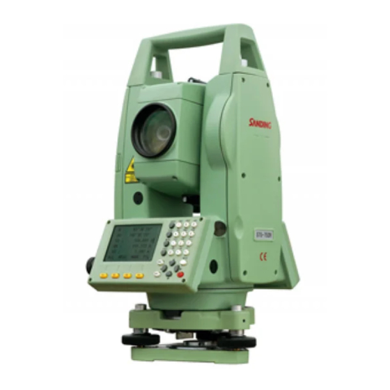
FOREWORDS Congratulations on the purchase of the SANDING Total Station STS-750RC Series. This manual is for the application of SANDING Total Station STS-750RC Series. Total Station STS-750RC is equipped with visible infrared laser EDM which can measure the distance without sighting a reflector. - Page 6 PRECAUTIONS 1. Do not collimate the objective lens directly to the sun without a filter. 2. Do not store the instrument in high and low temperature to avoid the sudden or great change of temperature. 3. When the instrument is not in use, place it in the case and avoid shock, dust and humidity.
- Page 7 Warning: Continuously looking straight at the laser beam is harmful. Prevention: Do not stare at the laser beam, or point the laser beam to others’ eyes. Reflected laser beam is a valid measurement to the instrument. Warning: When the laser beam emits on prism, mirror, metal surface, window, etc., it is dangerous to look straight at the reflex.
-
Page 8: Important Parts And Functions
1. IMPORTANT PARTS AND FUNCTIONS 1.1 IMPORTANT PARTS 1) objective lens 9) keyboard 2) center mark 10) tribrach lock 3) eyepiece 11) laser plummet (optical plummet) 4) telescope focusing knob 12) leveling screw 5) collimator 13) plate vial 6) Ni-H rechargeable battery 14) vertical tangent screw 7) horizontal tangent screw 15) SD card and USB port... -
Page 9: Display
1.2 DISPLAY STS-750RC SD20125 Version:12.09.17 【Measure】 PtID R.HT 1.000 m 0°00’00” Ⅰ 90°00’00” ----.---- m Mem. ----.---- m DIST RECORD ↓ 1.3 KEYPAD 1) Focus Actively measured field. 2) Symbols 3) Fixed keys Keys with firmly assigned functions. 4) Alphanumeric keys... -
Page 10: Fixed Keys
5) Navigation keys Control of input bar in edit and input mode or control of focus bar. 6) Soft key bar Displays functions that can be called up by the soft keys. 7) Function keys Are assigned the various functions displayed on the bottom of the screen. 1.4 FIXED KEYS [User]: User key can be defined. -
Page 11: Symbols
Soft Keys: Function [All] Starts angle and distance measurements, and saves the measured values. [DIST] Starts angle and distance measurements without saving the measured values. [RECORD] Saves displayed values. [ENH] Opens the coordinates input mode. [LIST] Displays the list of existed points. [SEARCH] Searches for the point entered. -
Page 12: Menu Tree
1.8 MENU TREE [Menu]>F1-F4: Confirms the selected menu. Press [PAGE] to view the next page. -
Page 13: Preparation For Measurement
2. PREPARATION FOR MEASUREMENT 2.1 UNPACKING AND STORE OF INSTRUMENT · Unpacking Place the case lightly with the cover upward, and unlock the case, take out the instrument. · Storing the Instrument Cover the telescope cap, place the instrument into the case with the vertical clamp screw and circular vial upwards (Objective lens towards tribrach), and slightly tighten the vertical clamp screw and lock the case. - Page 14 4) Precisely leveling by using the plate vial ①Rotate the instrument horizontally by loosening the Horizontal Clamp Screw and place the plate vial parallel to the line connecting leveling screw A and B, and then bring the bubble to the center of the plate vial by turning the leveling screws A and B.
-
Page 15: Battery Power Remaining Display
3) Use circular vial to roughly level the instrument. Adjust length of three legs of tripod, make the circular vial bubble of the instrument in the middle. 4) Use plate vial to level the instrument accurately. ①Rotate the instrument horizontally by loosening the Horizontal Clamp Screw and place the plate vial parallel to the line connecting leveling screw A and B, and then bring the bubble to the center of the plate vial by turning the leveling screws A and B. -
Page 16: Reflector Prisms
③When the measurement mode is changed, the battery power would not immediately show the actual status. The battery power indicating system shows the general status but not the instantaneous change of battery power. Battery Recharging Cautions: ☆ Battery should be recharged only with the original charger. ☆... -
Page 17: Mounting And Dismounting Instrument From Tribrach
2.5 MOUNTING AND DISMOUNTING INSTRUMENT FROM TRIBRACH Dismounting If necessary, the instrument (including reflector prisms with the same tribrach) can be dismounted from tribrach. Loosen the tribrach locking screw in the locking knob with a screwdriver. Turn the locking knob about 180° counter-clockwise to disengage anchor jaws, and take off the instrument from the tribrach. -
Page 18: Pointsearch
Numeric Mode: User can only enter numbers. Alphanumeric Mode: User can enter numbers and letters. By pressing several times you can toggle through the characters. For example: A->B->C->7. Press [F4] to switch between numeric and alphanumeric input mode. Sign The characters which can be input in STS-750RC Series are:A~Z . / $ % _ @ & * ? ! + -... - Page 19 Select job/input PT coord FIND OSET LIST 【Pt Search】 Press LIST to view the disk of the SANDING instrument and select the job. Then press PtID : FIND, it will show the point list of the job. ore Job Select job/input PT coord...
-
Page 20: Wildcard Search
2.9 WILDCARD SEARCH Use wildcard “*” representing those characters you are going to search. Wildcards are always used if the PtID is not fully known, or if a batch of points is to be searched for. Examples: *: All points of any length are found. A: All points with exactly the pointID “A”... -
Page 21: Routine Measurement
3. ROUTINE MEASUREMENT 3.1 DISTANCE SURVEY CAUTIONS In the measurement display it is possible to call up fixed keys, and function keys, as well as trigger keys and their functions. All shown displays are examples. It is possible that local software versions are different from the basic one. - Page 22 【EDM Settings】 Move the cursor to Reflect and choose the reflector mode you need. Fine [3] EDM Mode Reflect Prism Prism -30.0 mm ATMOS GRID SET. ↓ 【EDM Settings】 Move the cursor to Prism and input the prism constant. Fine [3] EDM Mode Reflect Non-P...
- Page 23 D=S·cosα H=S·sinα K=0.14 ……………………Atmosphere Refraction Modulus In formula: Re=6370 km ………………The Earth Curvature Radius α (or β) ………………...The Vertical Angle Calculated From Horizontal Plane (Vertical Angle) S ………………………….Oblique Distance NOTE: The atmosphere refraction modulus of this instrument has been set as: K=0.14.
- Page 24 【Atmospheric Data】 Input the Refraction factor, temperature, pressure, and Atmospheric PPM values. Refrcorr 0.14 Temp 20.0 °C Press SET. to save the change. Pressure 1013.0 hPa Atmos PPM 0 PPM BACK PPM=0. SET. Notice: The inputting scope of refraction factor is 0.00(SHUT) ~0.20. The inputting scope: Temperature:-40~+60°...
- Page 25 STEPS DISPLAY 【EDM Settings】 Press GRID. Fine [r] EDM Mode Reflect Prism Prism -30.0 mm ATMOS GRID SET. ↓ 【Grid Factor】 Input the scale and Ht.a.MSL. Scale 1.000000 Press SET. to save the change. Ht.a.MSL 0.0 m Grid 1.000000 BACK 0SET SET.
-
Page 26: Start Survey
Mem. 1.254 m 1.254 m DIST RECORD ↓ Set Hz TILT BEEP │← 【Measure】 【Measure】 PtID PtID Code SANDING R.HT 1.000 m R.HT 1.000 m 34°40′09″ Ⅰ Ⅰ 34°40′09″ 125.056 m 55°06′54″ Mem. 98.114 m Mem. 20.546 m 2.335 m CODE ↓... - Page 27 3.3.1 Setting Horizontal Circle STEPS DISPLAY 【Measure】 Turn to the third page of the function key PtID bar, and press Set Hz. R.HT 1.000m 34°40’09” Ⅰ 55°06’54” 20.546 m Mem. 1.254 m Set Hz TILT BEEP │← 【Hz Settings】 Current horizontal angle will be displayed. To set the current horizontal angle as the orientation, press SET.
- Page 28 3.3.3 Measurement As all settings are finished, you can start survey now. The survey result has four pages including all general survey data, press PAGE to check. STEPS DISPLAY 【Measure】 Input the PtID, reflector height, and code if necessary. PtID R.HT 1.000m 00°00’00”...
- Page 29 1) No beep 2) Fast beep 3) Permanent beep 3.3.4 Coding Codes contain information about recorded points. With the help of coding, points can be assigned to a particular group simplifying later processing. More information on coding can be found under “File Management”. The operational steps of simple coding: 1) Move the cursor to the “Code”...
- Page 30 【Code Search】 1/2 ▼ Or press CODE to search the code. Select/Input new code! Search ------ Code ------ Desc. ------ Info1 ------ Infor2 ------ RECORD Notice: the saving sequence of coding data and measurement can be set in “Setting”. The settings of recording the code are: Save before, Save after. Save before: to save the codeblock before the measurement.
- Page 31 measurement will be triggered and the measured data and code will be saved. A total of 100 codes can be assigned; you may create codes with “Codelist Manager” included in the software CD, and transfer the code list to the total station.
-
Page 32: Functions
4. FUNCTIONS Several functions can be called up via [FNC] key. Functions can also be started directly from different applications. Each function from the FNC menu can be assigned to the [USER] key. 4.1 LEVELING This function enables the electronic bubble and the range of intensity setting of the laser plummet. -
Page 33: Deleting Last Record
If the height offset value is positive, it indicates that the offset point is higher than the measurement point. STEPS DISPLAY 【Function】 ▼ Press FNC on the keyboard. F1 Level Press F2 to enter to enter to Target Offset function. F2 Target Offset F3 Delete Last Record F4 Main Settings... -
Page 34: Main Settings
STEPS DISPLAY 【Function】 ▼ Press F3 to enter to Delete Last Record. F1 Level F2 Target Offset F3 Delete Last Record F4 Main Settings Press OK to confirm to delete last record. Sure delete final record? CANCEL 4.4 MAIN SETTINGS This enables to change the most important settings, which is the same as [MENU] >... - Page 35 OFF: Tilt compensation is switched off. 1-axis: V-angle relate to the plumb line. Tilt Crn. 2-axis: V-angle refer to the plummet line and the (Tilt 1-axis Hz-directions are corrected by the standing axis tilt. Correction) 2-axis The compensator setting remains active even after the instrument is switched off.
-
Page 36: Height Transfer
° ′ ″ (degree, sexagesimal), possible angle values: 0° ~ 359°59′59″ (degree, decimal): possible angle dd. mm. ss values:0º ~359.9999º gon, possible angle values: 0gon~399.9999gon Angle Unit mil, possible angle values: 0mil~6399.99mil The setting of the angle units can be changed at any time. - Page 37 STEPS DISPLAY Turn to Page 2/4 in Function menu. 【Height Transfer】1 Select Target Meas! PtID ------ Press F1, Height Transfer. R.HT 1.500 M Ⅰ ----.--- m ----.--- m Mem. INS.HT VIEW │← 【Height Transfer】 Turn to the third page of function key bar StnPt OCC1 and press INS.HT to set the instrument...
- Page 38 【Ht.Tran.Result】 1/2 ▼ The height of station is calculated. StnPt OCC1 Press PAGE to display the Page 2/2. 8.250 m Corr. 0.000 m NoPts Press FACE, and focus the same point in Face Ⅱ, then press All to measure the same point in Face Ⅱ.
-
Page 39: Hidden Point Measurement
4.6 HIDDEN POINT MEASUREMENT The program allows measuring to a point that is not directly visible, using a special hidden-point rod. The Picture shown above implies: 1) E, N, H of Hidden Point 2) Rod Length 3) Distance R1-R2 STEPS DISPLAY 【Hidden Point】... -
Page 40: Free-Coding
Focus on the second prism, and press All 【Hidden Point】 (or DIST + RECORD). Meas second prism! PtID 50°20′50″ Ⅰ 102°40′00″ ----.--- m Mem. DIST RECORD ROD/ED 【Hidden Point】 After measuring these 2 prisms, the result will show. Desc. ------ Press FIINISH to save the result. -
Page 41: Edm Tracking
STEPS DISPLAY 【Check Tie】 1/2 ▼ Before entering to this function ,make 186°28′36″ sure that there’re at least 2 valid Grade 9.0% measurements. △ 4.298 m Turn to Page 2/4 in Function menu. △ 4.316 m △ 0.396 m Press F4, Check Tie. AZ of 2 points, and the relations among HD, SD, and VD are displayed. -
Page 42: Light On/Off
The last active measurement mode remains set when the instrument is switched off. 4.10 LIGHT ON/OFF Switches display light on/off. 4.11 LASER POINTER ON Switches the visible laser pointer on. It will be switched off after 60 seconds automatically. 4.12 RETICLE ILLUMINATION ON/OFF Switches the reticle illumination on or off. -
Page 43: Programs
5. PROGRAMS APPLICATION PRE-SETTINGS There are programs that precede the application programs and are used to set up and organize data collection. They are displayed after selecting an application. Users can select the start programs individually. 【Setting Meas.】 Setting Job Setting Station Set Orientation Start... -
Page 44: Setting Station
【View Job】 The screen shows the file list. Press F4 to the next page, then press NEW to add a DEFAULT.RAW 1.82KB 02-03 new job. SANDING.RAW 1.26KB 02-04 Rename DELETE ↓ New Meas Job Enter the job name, operator name, etc. -
Page 45: Setting Orientation
STEPS DISPLAY 【Setting Station】 Press F2 to enter to Setting Station. Input Station PtID! Press SEARCH, or LIST to find an existed (known) point from internal memory. StnPt OCC1 Or press ENH to input the PtID and its coordinates and save it in the job. SEARCH LIST 【Setting Station】... - Page 46 【Set Manually】 Input the backsight PtID, reflector height, and a random AZ value. BsPt R.HT 1.500 m 9°11′25″ Sight BsPt Meas&Rec! SET. 0SET 【Setting Meas.】 Press All to trigger the measurement. Setting Job Or press SET. to set the orientation without activating the measurement.
- Page 47 3) Input and confirm the reflector height. Orientation coordinates can be either obtained from the internal memory or entered manually. STEPS DISPLAY 【Orientation】 Press F3 to enter to Set Orientation. Press F2 to set the orientation with coordinates. F1 Set manually F2 Known Point 【Known Pt】...
- Page 48 Then a dialog saying “Want More 【Orientation Result】 Measurement?” pops up. Press OK to Nopts. start another measurement. Press Station CANCEL to show the orientation result. HzCor 172°22′57″ Press OK to confirm the orientation set. St.Dev 0°00′20″ RESID 【Orientation Residuals】 Or press RESID to show the residuals.
-
Page 49: Surveying
SIGNIFICANT INFORMATION If the orientation is only measured in telescope Face II, the HZ orientation is based on telescope Face II. If measured only in telescope Face I or mixed the HZ orientation is based on Face I. The prism height may not be changed during measurements in the first and second telescope position. -
Page 50: Staking Out
Enter the PtID, reflector height, and 【Measure】 1/3 code, and press All (or DIST + PtID RECORD) to trigger the measurement R.HT 1.500 m Code and save the result. Ⅰ 0°00′00″ 90°00′00″ Mem. ----.--- m DIST RECORD ↓ 【Measure】 1/3 After measurement, the PtID will be PtID automatically plus 1. - Page 51 RECORD ↓ 【Coordinate Input】 Input the PtID you want to stake out in the field of “Find”, or search via wildcard “*”. SANDING PtID ------ ----.--- m Or turn to the second page of the function key bar, and press ENH to a new point to ----.--- m...
- Page 52 【Stake Out Input Data】 After entering the coordinates, press OK to confirm. ----.--- m ----.--- m ----.--- m BACK 0SET Notice: [MANUAL]: Data that was input will not be saved in the job. Soft keys: DIST: Starts measurement and calculation of the stake-out elements. RECORD: Saves the displayed values.
- Page 53 STEPS DISPLAY Confirm the point to be stake out. 【Stake Out】 1/3 ▼ Find PtID Type Known Ⅰ △Hz -85°51′31″ △ 2.055 m Mem. △ ----.--- m DIST RECORD ↓ Press PAGE to turn to Page 2/3. 【Stake Out】 2/3 ▼...
- Page 54 【Stake Out】 1/3 ▼ When both △Hz and △ are 0, it means the current position of the prism is Find the point to stake out. PtID Type Known Ⅰ △Hz △ 0°00′00″ displays the offset to dig or fill. : Distance to dig.
- Page 55 Collimate the current prism, and press 【Stake Out】 2/3 ▼ DIST to measure. The system calculates PtID and displays the offsets between the Type Meas. R.HT 1.800 m measured point and the point to stake Ⅰ △LOff 4.086 m out. △TOff -2.361 m Mem.
- Page 56 measurement point. STEPS DISPLAY Turn to Page 3/3 to start Coordinates 【Stake Out】 3/3 ▲ PtID Stake Out. Type Meas. R.HT 2.000 m Select or input the point to stake out. Ⅰ △X/N ----.--- m △Y/E Enter the reflector height. ----.--- m Mem.
- Page 57 【Stake Out】 3/3 ▲ Then the current position of the prism is the point to stake out. △H indicates the PtID distance to dig or fill. Type Meas. △H is positive: to fill. R.HT 2.000 m △H is negative: to dig. △X/N 0.000 m Ⅰ...
-
Page 58: Free Station
Move the prism far or close according to 【Side Shot Stake Out】 the arrows, until △ is 0 m. PtID △Hz 0°00′00″ △ is positive: move the prism far Ⅰ 0.000 m away from the station. △ Mem. △ is negative: move the prism close to the station. - Page 59 Press F3 to enter to Free Station function in the menu of Programs. Setting job Setting limit Start 【Setting Job】 5/8 Press F1 to set a job. SANDING Select the job name, or create a new job Name JOHN by press ADD. Date 2011.01.01 After setting the job, press OK.
- Page 60 【Free-Station TGT PT】 Input the target point ID and reflector height, and press OK to confirm. PtID R.Ht 1.500 m You can also call up a point by SEARCH or LIST. ↓ SEARCH LIST 【Free-Station Measure】 Collimate the Target Point 2 and press All PtID to trigger the measurement.
-
Page 61: Cogo
Warnings/Messages Important Messages Meaning Selected point has no valid data! This message occurs if the selected target point has no easting or northing coordinate. Max 5 points supported! If 5 points have already been measured and another point is selected, the system supports a maximum of 5 points. - Page 62 5.7.1 Traverse & Inverse 5.7.1.1 Traverse Known: P1: The known point α: Direction from P1to P2 d1: Slope distance from P1to P2 d2: Offset right that is positive d3: Offset Left that is negative Unknown: P2:COGO point P3: COGO point with positive offset P4: COGO point with negative offset STEPS DISPLAY...
- Page 63 【COGO New Point】 Press CALC to calculate. Input a new PtID. New Pt ------ Press RECORD to save. 20.000 m 10.000 m Or press STAKE to start stake out. The system will ask “Record New Point?” Press OK to save the new point to the job.
- Page 64 5.7.1.2 Inverse The known data: P1: The first known point P2: The second known point The unknown data: α:Direction from P1 to P2 d1: Slope distance between P1 and P2 . d2: Horizontal distance between P1 and P2 d3: Height distance between P1 and P2 STEPS DISPLAY 【Inverse】...
- Page 65 5.7.2 Intersections 5.7.2.1 Bearing-Bearing The known data: P1: The first known point P2: The second known point α1: Direction from P1 to P3 α2: Direction from P2 to P3 The unknown data: P3: COGO point STEPS DISPLAY 【Bearing-Bearing】 In COGO Main Menu, press F2 to enter to Intersection.
- Page 66 5.7.2.2 Bearing-Distance Intersection The known data: P1: The first known point P2: The second known point α: Direction from P1 to P3 and P4 r: Radius, i.e. distance from P2 to P3 or P4 The unknown data: P3: The first COGO point P4: The second COGO point STEPS DISPLAY...
- Page 67 5.7.2.3 Distance-Distance Intersection The known data: P1: The first known point P2: The second known point r1: Radius, as defined by the distance from P1 to P3 or P4 r2: Radius, as defined by the distance from P2 to P3 or P4 The unknown data: P3: The first COGO point P4: Second COGO point...
- Page 68 5.7.2.4 By Points The known data: P1: The first known point P2: The second known points P3: The third known points P4: The fourth known points a: Line from P1 to P2 b: Line from P3 to P4 The unknown data: P5: COGO point STEPS DISPLAY...
- Page 69 5.7.3 Offset 5.7.3.1 Distance-Offset The known data: P1: Baseline start point P2: Baseline end point P3: Lateral point The unknown data: d1: Difference in length/abscissa (HD) d2: Lateral deviation/ordinate (Offset) P4: Base point STEPS DISPLAY 【Distance-Offset】 In COGO Main Menu, press F3 to start Define Baseline! Offset COGO.
- Page 70 5.7.3.2 Point-Offset The known data: P1: Baseline start point P2: Baseline end point a: Difference in length/ abscissa (HD) b: Lateral deviation / ordinate (Offset) The unknown data: P3: Lateral point STEPS DISPLAY 【Point-Offset】 Press F2 to start Point-Offset. Define Baseline! Enter the known PtID of P1 and P2.
-
Page 71: Tie Distance
5.7.4 Extension “Extension” is used to compute extension points from the baseline. The known data: 1: Start point of baseline 3: End point of baseline △ L1 or △ L2: Distance The unknown data: P2, P4: Extended point STEPS DISPLAY 【Extension】... - Page 72 5.8.1 Polygonal (A-B, B-C) STEPS DISPLAY 【Polygonal】 1/2 On Page 2/3 of Programs, press F1 to start Tie Distance. Point1 After setting job, station, R.HT 1.500 m orientation, presses F4 to start. ----.--- m And press F1 to start Polygonal (A-B, ----.--- m Ⅰ...
- Page 73 【Tie Distance】 1/2 ▼ It displays the Tie Distance result. Point1 △ : HD between Point A and Point B. Point 2 △ : SD between Point A and Point B. △ Grade -49.6% : VD between Point A and Point B. Grade: the slope between Point A and 0.663 m △...
-
Page 74: Area Measurement (Plane)
【NewPt2】 1/2 Input the PtID of end point A and its prism height. NewPt1 NewPt2 R.HT 1.500 m ----.--- m Ⅰ ----.--- m ----.--- m Mem. ↓ SEARCH LIST 【Tie Distance】 1/2 ▼ It displays the Tie Distance result. Point1 △... - Page 75 a: Start point b: Perimeter, polygonal length from start point to c: Calculated area always closed to the start point P1, projected onto the horizontal plane. STEPS DISPLAY 【Area】 1/2 On Page 2/3 of Programs, press F2 to start Area (Plan). PtID After setting...
-
Page 76: Remote Height Measurement (Rem)
Point number counts from the existed record. 5.10 REMOTE HEIGHT MEASUREMENT (REM) If the prism cannot be put at the point to be measured, user can firstly collimate base prism below it and measure the horizontal distance. Then collimate the remote point to calculate the vertical difference. - Page 77 If the prism height is unknown: STEPS DISPLAY 【Base Point】 On Page 2/3 of Programs, press F3 to Sight Meas Base Pt! start Remote Height. After setting job, station BasePt orientation, press F4 to start. Turn to the 2 page of the function key R.HT 1.500 m Ⅰ...
-
Page 78: Reference Line / Arc
5.11 REFERENCE LINE / ARC If equipped with REFERENCE LINE/ARC, then ROAD and CONSTRUCTION SITE STAKE OUT will be deleted. This program facilitates stake-out or checking lines for buildings, sections of road, simple excavations, etc. 5.11.1 Reference Line A reference line can be defined as a known base line. The reference line can be offset longitudinally, in parallel or vertically to the base line, or be rotated around the first base point as required. - Page 79 【Baseline Define】 1/3 ▼ Set the 2 base point and its prism height with the methods above. Meas. Second Pt! Point1 Point2 R.HT 1.000 m Ⅰ ----.--- m ----.--- m Mem. ↓ SEARCH LIST 【Ref. Line Define】 Then a Base Line is defined. Baseline Shifts! 1.369 m △...
- Page 80 Definition of Reference Line: 【Ref. Line Define】 Baseline Shifts! 1.369 m △ Offset 0.000 m Line 0.000 m 0.000 m Rotate 0°00′00″ NewBL MEAS STAKE 0SET Offset: Parallel offset of the reference line to the right, referred to the direction of the base line.
- Page 81 STEPS DISPLAY 【Ref. Line Define】 After defining the base line, input the T Baseline Shifts! offset (offset), L offset (Line), elevation 1.369 m (H/Z) and the angle to rotate. △ Offset 0.000 m Line 0.000 m 0.000 m Rotate 0°00′00″ NewBL MEAS STAKE...
- Page 82 5.11.1.4 Orthogonal Stake-Out User can enter longitudinal, transverse and height offsets for the target points to be set-out related to the reference line. The program calculates the difference between a measured point and the calculated point. The program displays the orthogonal (pLine, pOffset, p ) and the polar (pHz,△...
- Page 83 【Orthogonal SO】 1/2 Collimate the prism and press DIST to start measurement. PtID R.HT 2.000 m △Hz -10°10′05″ If you want to redefine the reference line, 2.020 m press Ref.Ln in the 2 page of the △ Ⅰ -----.--- m function key bar.
- Page 84 5.11.2 Reference Arc This procedure allows user define a reference arc, and the measure or stake out with respect to the arc. Off: Perpendicular distance from arc. All arcs are defined in clockwise direction. All calculations are made in two dimensions. Steps:...
- Page 85 【Define Ref. Arc】 1/3 ▼ Set the PtID of the center point of the arc and its prism height. Sight Meas CenterPt Input the PtID and its prism height and Center press All to start measurement. You can R.HT 1.000 m also call up the point by SEARCH or Ⅰ...
- Page 86 【Reference Arc】 Input the radius and press OK. Input Arc Radius! Radius ----.--- m 【Reference Arc-Window】 Then a reference arc is defined. Now you are to decide whether to Center ------ measure or to stake out. StartPt End Pt Radius 12.650 m NewArc MEAS...
- Page 87 【Line&Offset Measure】 No matter the point to measure is called up from the memory or input manually, PtID the system calculates the line and offset R.HT 2.000 m Line 14.125 m between this coordinates Offset 2.364 m reference line. Ⅰ △...
- Page 88 a) Stake-Out Point Point can be staked out by entering a line and an offset value. dOffset: The perpendicular distance from stake out points to arc sect. dLine: The arc length from measurement point to stake-out point and vertical line of reference arc (Line).
- Page 89 b) Stake Out Arc This allows staking out a series of equidistant points along the arc. 【Stake Out Arc】 Press F2 to start Stake Out Arc. PtID Input the PtID of the point to stake out. Miscls End Arc Select distributing mode misclosure.
- Page 90 【Stake out Reference Arc】 When △Hz and △ is 0, it means the current position of the prism is the PtID point to stake out. R.HT 2.621 m △Hz △ -00°00′00 mean the distance to dig or fill. 0.000 m △...
- Page 91 【Stake Out Chord】 Press F3 to start Stake Out Chord. Input the PtID of the point to stake out. PtID Select distributing mode Miscls End Arc ChordL 0.000 m misclosure. Line 0.000 m Input the length of the chord to stake out, Offset and the system will calculate the Line 0.000 m...
- Page 92 β: Angle SP: Start point of arc EP: End point of arc MP: measurement point 【Stake Out Chord】 Press F3 to start Stake Out Angle. Select distributing mode PtID misclosure. Miscls End Arc Angle 0.000 m Input the angle to stake out, and the Line 0.000 m system will calculate the Line according to...
-
Page 93: Road
5.12 ROAD If equipped with ROAD, then REFERENCE LINE/ ARC will be deleted. This program enables you to easily define a line or curve or spiral as a reference for measurements and stake outs. It supports chainages, as well as incremental stake-outs and offsets. - Page 94 The screen displays: current chainage, the azimuth angle of the tangent on the chainage, and the function key of the establishing new line. The system provides four functions: defining line, curve, spiral, and point. Select a function key, enter the detailed information of the chainage, the alignment elements will be created.
- Page 95 【HZ Alignment Type】 It returns to the main menu of defining alignment. It displays the end chainage and its azimuth. Chain. 1048.420 m 25°00′00” LINE SPRIAL POINT Curve Press ARC in “Hz Alignment type” menu to define the curve. A curve consists of arc length and radius.
- Page 96 【HZ Alignment Type】 Chain. 1071.561 m 91°17′38” LINE SPRIAL POINT Spiral Press SPRIAL in “HZ Alignment Type” menu to define spiral. A spiral consists of the minimum radius and arc length. The rule of radius value: along the forward direction of the curve. When the curve turns right, the radius value is positive. When the curve turns to left, the radius value is minus.
- Page 97 【HZ Alignment Type】 It returns to the main menu of defining alignment. It displays the end chainage and its azimuth. Chain. 1091.561 m 119°56′31” LINE SPRIAL POINT Point Press POINT in “HZ Alignment Type” menu to define point. A point element consists of coordinate, radius and spiral factors A1 and A2.
- Page 98 【Define HZ AL】 4/3 Input the coordinates N/X, Y/E, radius and spiral parameters A1 and A2. Type POINT ----.--- m ----.--- m Press NEXT and then OK to save the Radius ----.--- m edited alignment data. ----.--- m ----.--- m ↓...
- Page 99 data. LAST [F2]: Goes to the end of the file, and displays the last alignment data. LIST [F1]: Displays all the known points and measured data in this job in list. This function can be applied only when the point element of horizontal alignment data is able to be input (or edited).
- Page 100 5.12.4 Defining Vertical Alignment A vertical alignment consists of a series of intersections, including a chainage, height and curve length. The length of start point and end point must be zero. Chainage 1000 1300 1800 2300 Elevation Curve Length Intersections can be entered in any order. After entering one point data, press ENT to save it and go to next inputting screen.
- Page 101 To stake out alignment, the alignment type should be defined first. 2 methods of defining horizontal alignment are available: installing in the computer via the software “SANDING SURVEY OFFICE” provided by Sanding Optic-Electric Equipment Co., Ltd; or inputting manually in program “Road”.
- Page 102 Rules of alignment stake-out data: Offset left: Horizontal distance between the left chainage and central line. right: Horizontal distance between the right chainage and central line. Vertical Difference Left (right): vertical difference between left (right) chainage and the central line point. In the process of stake-out, user should first stake out points on the central line, then the featured points on both sides.
- Page 103 【Alignment S-O】 Input the starting chainage, chainage increment, HD from side chainage to StartC 100.000 m central line, and HD if necessary. Incre. 1.000 m Offs_L 1.000 m Offs_L: HD from left chainage to central Offs_R 2.000 m line. HtDi.L Offs_R: HD from right chainage to central 1.000 m line.
- Page 104 L_OFFS: This key is used to stake out left chainage. Press it to display the offset and the height difference of the left chainage. R_OFFS: This key is used to stake out right chainage. Press it to display the offset and the height difference of the right chainage. +CHAIN: The key is used to increase the chainage.
- Page 105 Indeed, the fill/cut value that is input here is a ratio. The fill/dig data can be entered through left and right slopes. In terms of fill/dig, use positive symbol to input the required slope, the software selects an appropriate slope in the list according to the actual position of the point. Dig/fill is decided via the estimated height of hinge point.
-
Page 106: Construction Site Stake Out
【Slope Stake Out】 Input the ratio to cut or fill. Left (1:n) Then choose the left or right slope to 1.350 Fill 1.000 stake out. Right (1:n) 1.200 Fill 1.650 LEFT RIGHT 【Slope Stake Out】 Input the prism height. PtID C100+10.0S Collimate the prism and press DIST. - Page 107 【Setting Job】 1/3 Set the job. Press ADD to add a new job. Name ------ Date 2011.01.16 Press OK to set the job you just selected Time 16:50:28 as the current job. 【Programs】 3/3 Press F1 to set a job again. Press F2 to set the EDM F1 Setting Job Press F3 to define a new construction...
- Page 108 5.13.2 Shifting Line [ShiftL]: Input horizontal shifting value to horizontally shift the line. The line can be horizontally shifted according to the requirement of job. STEPS DISPLAY 【Stake Out】 To shift the construction site, turn to 2 PtID: page of the function key bar and press ShiftL.
- Page 109 Information shown in AS-Builtcheck is introduced follow: Longitude (in direction of the line) is positive: expresses the point measured lies between the start point and end point of the line. Right latitude offset is positive: expresses the point measured is on the right of the line.
- Page 110 The height of the line start point is always used as the reference height. The graphics are scaled to give a better overview. Therefore it’s possible that the station point moves in the graphic. Be aware that the start point and the end point of the line are measured in the previous coordinate system.
-
Page 111: File Management
6. FILE MANAGEMENT File management includes all the functions of inputting, editing, examining data and communication in the field. 【File Management】 1/3 ▼ F1 Job F2 Known points F3 Measurements F4 Codes 【File Management】 2/3 F1 Initialize Memory F2 Memory Statistic F3 U Disk Mode 【File Management】... - Page 112 【File Management】 1/3 ▼ Press F1. F1 Job F2 Known points F3 Measurements F4 Codes 【View Job】 1/17 It displays the information of the current SANDING job. Name ------ To select another job, press F1 to view Date 2011.4.11 the memory Time...
- Page 113 Press F1. F1 Job F2 Known points F3 Measurements F4 Codes 【View Job】 1/17 It displays the information of the current job. SANDING To add another new job, press F1 to view Name ------ the memory Date 2011.4.11 Time 14:44:12...
- Page 114 Press F1. F1 Job F2 Known points F3 Measurements F4 Codes 【View Job】 1/17 It displays the information of the current job. SANDING Name ------ Press F1 to view the files in the disk. Date 2011.4.11 Time 14:44:12 Note 1...
-
Page 115: Known Point
【View Job】 The screen shows the file list. Press F4 to DEFAULT.RAW 1.82KB 02-03 the next page, then press DELETE to SANDING.RAW 1.26KB 02-04 delete the selected job. Rename DELETE ↓ 6.2 KNOWN POINT This application allows user to launch operations of searching, editing, and deleting known point in each job in internal memory. - Page 116 Press SEARCH. 206.020 m 161.200 m 92.026 m SEARCH DELETE EDIT Input the PtID or wildcard “*” and press 【Search】 ENT. A:\SANDING.PTS PtID BACK 【View Known Pt】 It will display the searching result. A:\SANDING.PTS PtID 0.000 m 0.000 m 0.000 m...
- Page 117 【Input Known Pt】 Input the information of a new point and press SAVE. A:\SANDING.PTS PtID ------ 0.000 m If the PtID exists, the program will call the 0.000 m that point. If need to save as another 0.000 m point, press to input the new point name.
-
Page 118: Measurement Data
STEPS DISPLAY 【View Known Pt】 Choose the point you want to delete and A:\SANDING.PTS press DELETE. PtID 0.000 m 0.000 m 0.000 m SEARCH DELETE EDIT 【View Known Pt】 Press OK to confirm to delete. Or press CANCEL to cancel to delete. - Page 119 STEPS DISPLAY 【File Management】 1/3 ▼ Press F3 to manage the measurements. F1 Job F2 Known points F3 Measurements F4 Codes 【View Measurements】 Choose the job where you want to manage the measurement. SANING To view all the measurement in the job, StnPt Pt ID press VIEW.
- Page 120 STEPS DISPLAY 【View Measurements】 Input the job name. The point ID to be input is based on the SANING Station point. Input the StnPt or the StnPt wildcard "*". PtID Input the PtID or the wildcard "*". Press F4 to view the measurement data. F4 View All Meas.
-
Page 121: Coding
6.4.1 Manual Code Input The code in code database can be input manually, or created by the communication software provided by Sanding Company, and transmitted to the instrument. Each code has one item of explanation and a maximum of 8 attributes that has no more than 16 characters. -
Page 122: Initializing Internal Memory
【Code View/Del】 1/2 ▲ B: Move the cursor to "Find", and insert Find the code or the wildcard "*", press ENT Code NR01 1: If the code exists, the code will be Desc. SITELINE displayed on the screen 2: For wildcard "*", all the code can be Info1 NR.12 Info2... -
Page 123: Memory Statistic
ROAD Deleting all the road data, including the HZ, VT or all the alignment. CODE Deleting all the code data After deleting, the data cannot be recovered, therefore, before operation, be sure that the useful data have been downloaded or stored. 6.6 MEMORY STATISTIC Displays the information of memory, such as: ·... - Page 124 STEPS DISPLAY 【File Management】 2/3 Press F3 to enter to U Disk Mode. F1 Initialize Memory F2 Memory Statistic F3 U Disk Mode 【U Disk Mode】 Screen shows "Connected to PC". Then users can check the local disk in MY COMPUTER.
-
Page 125: Data Output/Data Import
LIST to select the TXT file in the SD card. Press OK File name SANDING Time 2010.10.20 Time 12:00:00 LIST 【Code data】 Start exporting code data SANDING.TXT in the SD card. From A:\PCODE.DAT B:\SANDING.TXT BACK * All the code data stored in the PCODE.DAT file. -
Page 126: Usb Send Data/Usb Receive
Time 2010.10.20 Time 12:00:00 LIST 【HZ Alignment data】 Start importing the HZ Alignment data to SANDING.TXT in the SD card. From B:\SANDING.TXT A:\Road.HAL BACK * All the HZ Alignment data stored in the Road.HAL file. 6.9 USB SEND DATA/USB RECEIVE Before transferring data through the USB cable, please ensure the PC has been installed the miniUSB cable driver. - Page 127 F3 USB Send Data (10) F4 USB Receive (11) Press F1 to send the code data to PC 【USB Send Data】 through SANDING SURVEY OFFICE. F1 Code F2 HZ Alignment F3 VT Alignment The screen shows USB initializing..【USB Send Data】...
- Page 128 F3 USB Send Data (10) F4 USB Receive (11) 【USB Send Data】 Press F1 to receive the known point data from a PC through SANDING SURVEY F1 KnownPt OFFICE. F2 Code F3 HZ Alignment F4 VT Alignment Choose the job to receive the known 【KnownPt Job】...
-
Page 129: Communication Setting
7. COMMUNICATION SETTING To communicate data between computer and instrument, you must set communication parameters. 【Comm Parameters】 Baudrate 57600 DataBits Parity None End Mark CR/LF Stop Bit SET. BAUD RATE: The optional baud rates are as follows: 1200, 2400, 4800, 9600, 19200, 38400, 57600, and 115200 [BIT /SECOND]. -
Page 130: Data Transfer
8. DATA TRANSFER With this special function measured data can be transferred via the serial interface to receiver (e.g. a data collector) or USB interface to a PC. Using this type of transfer the success of the transfer is not checked. Job: Selection of job from which data should be transferred. -
Page 131: System Information
9. SYSTEM INFORMATION Displays helpful information and sets data / time. 【System Information】 Battery Date 2011.04.11 Time 14:14:48 Version 10.06.29 Type STS750R Number SD13752 DATE TIME FORMAT · Battery Remaining battery power (e.g. 80%). · Date Displays the current date. ·... -
Page 132: Check And Adjustment
10. CHECK AND ADJUSTMENT This instrument has undergone a strict process of checking and adjustment, which ensures that it meets quality requirement. However, after long periods of transport or under a changing environment, there may be some influences on the internal structure. -
Page 133: Inclination Of Reticle
circular level is centered at last. 10.3 INCLINATION OF RETICLE Check 1. Sight object A through the telescope and lock the horizontal and vertical clamp screws. 2. Move object A to the edge of the field of view with the vertical tangent screw (point A′). - Page 134 2. Sight object A in Face I and read the horizontal angle value. (e.g.: Horizontal angle L=10°13′10″). 3. Loosen the vertical and horizontal clamp screws and rotate the telescope. Sight object A in Face Ⅱ and read the horizontal angle value. (e.g.: Horizontal angle R= 190°13′40″).
-
Page 135: Vertical Index Difference Compensation
【Hz-collimation】 Turn to Face II, collimate the same target and press MEAS. <STEP-2> Reverse 152°25’58” 267°0’20” Sight target MEAS 【Hz-collimation】 It shows the difference. Press SET. to correct the difference. Press BACK to quit without saving the H const. 0°00’11” correction. -
Page 136: Vertical Index Difference (I Angle) & Setting Vertical Index 0
has exceeded 3ˊat this time and exceeds the designated compensation range. 4. Rotate the above screw to its original position, and the instrument display screen will show the vertical angle again, meaning that the vertical index difference compensation function is working. Adjust If the compensation function is not working, send the instrument back to the factory for repair. -
Page 137: Transverse Axis Error Compensation Adjustment
【V-index】 Turn to Face II, collimate the same target and press MEAS. <STEP-2> Reverse 155°27’01” 252°43’47” Sight target MEAS 【V-index】 It shows the difference. V const. 3°58’11” Press SET. to correct the difference. Press BACK to quit without saving the VADJ_T 0°00’33”... -
Page 138: Optical Plummet
STEPS DISPLAY 【Adjustment】 ▼ Press F3 to start to adjust Horizontal Axis. F1 V-index F2 Hz-collimation F3 Horizontal Axis F4 V0/Axis (Cons. List) 【Horizontal Axis】 In Face I, collimate the target, and press [0/10] MEAS 10 times. <STEP-1> Front 335°28’41” 107°16’20”... -
Page 139: Instrument Constant (K)
view. 3. Adjust the leveling screws so that the center mark of the optical plummet coincides with the intersection point of the cross on the paper. 4. Rotate the instrument around the vertical axis, and observe whether the center mark position coincides with the intersection point of the cross at every 90° . 5. - Page 140 3. Set the instrument on Point B and center it accurately, measure the Horizontal Distance of BC accurately. 4. Then the Instrument Constant can be obtained: K=AC-(AB+BC) K should be near to 0, If |K|>5mm, the instrument should be strictly inspected in the standard baseline site, and adjusted according to the inspection value.
-
Page 141: Parallel Between Line Of Sight And Emitting Photoelectric Axis
10.10 PARALLEL BETWEEN LINE OF SIGHT AND EMITTING PHOTOELECTRIC AXIS Check 1. Set the reflector 50m away from the instrument. 2. Collimate the center of the reflector prism with reticle. 3. Switch on the instrument, and enter into Distance Measurement Mode. Press DIST (or All) to measure. -
Page 142: Tribrach Leveling Screw
If the spot illuminates the cross, the achievable adjustment precision has been reached; if it lies outside the limits of the cross, the direction of the beam needs to be adjusted. If the spot on the more reflective side of the plate is too bright (dazzling), use the white side instead to carry out the inspection. -
Page 143: Specification
11. SPECIFICATION MODEL STS-752RC STS-755RC DISTANCE MEASUREMENT single prism 5.0km reflectorless 350m accuracy with reflector: 2mm+2ppm; without reflector: 3mm+5ppm reading max: 99999999.999 min: 1mm measuring time fine: 1s; tracking: 0.5s atmospheric refraction & manual input, auto correction earth curvature correction... - Page 144 0.5m ~ ∞ focusing range field of view 5° OTHER Display type 2 sides, alphanumeric keyboard Laser plummet optional ON-BOARD BATTERY type rechargeable Ni-H battery voltage operating time 8 hours DIMENSION & WEIGHT dimension 200 X 190 X 350mm weight 6.0kg...
-
Page 145: Accessories
12. ACCESSORIES ITEM Carrying Case 1 pc Main Body 1 pc Backup on-board Battery 1 pc Charger 1 pc Plumb Bob 1 pc Correction Pin 2 pcs Fur Brush Screwdriver Hexagon Wrench 2 pcs Cloth Dryer Operation Manual Certificate... -
Page 146: [Appendix-A] Calculating Road Alignment
[APPENDIX-A] CALCULATING ROAD ALIGNMENT The road alignment stake-out program can stake out the alignment elements including straight, arc and transition curve. NOTE: 1) Road alignment data can be uploaded from computer or can be entered manually. 2) Road alignment data is managed by chainage. 1. -
Page 147: Calculation Road Alignment Elements
1050.000 Press [ENT] and then press [F4] (PT), Enter the following data: 1300.000 1750.000 100.000 80.000 80.000 Enter the following data in the above way: 1750.000 1400.000 200.000 0.000 0.000 2000.000 1800.000 0.000 0.000 0.000 The format of the data above transmitted to computer is as follows: START 0.000,1050.000,1100.000 CRLF PT 1750.000,1300.000,100.000,80.000,80.000 CRLF PT 1400.000,1750.000,200.000,0.000,0.000 CRLF... - Page 148 0.32 = 0.32 rad =18° 20′06″ 2 3) Calculation of transition coordinates A ..) 9360 ...
- Page 149 –1.7(1 / tan 111°55′47″) +31.891 =148.06015 + 1.8326 + 0.6844 +31.891 =182.468 7) Calculation of the coordinate KA1 Bearing from BP to IP1 74° 03′16.6″ 1300 –182.468 * cos 74° 03′16.6″=1249.872 m ...
- Page 150 (Bearing from IP1 to IP2) = 322° 07′30.1″ (Bearing from IP2 to EP) = 57° 59′40.6″ 1750 - 221.615 * cos322° 07′30.1″ =1575.068 m 1400 - 221.615 * sin322°07′30.1″ =1536.058 m ...
- Page 151 Start point coordinate (BP) 1100.000 m 1050.000 m straight line ( between BP and KA1 ) Bearing 74° 03′16.6″ Distance 545.543 m Transition clothoid (between KA1 and KE1) Radius -100 m (“-”sign is turn left curve toward the end point ) Length 64 m ARC (between KE1 and KE2)
Need help?
Do you have a question about the STS-752RC and is the answer not in the manual?
Questions and answers