Table of Contents
Advertisement
Available languages
Available languages
Quick Links
Operating Instructions
®
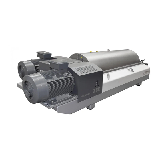
TRICANTER
Z 8E
Machine number: 019.026.21
Project number:
P32825
Revision 1
Original operating instructions
Edition: 2018-02-01
© Copyright by Flottweg SE. All rights reserved.
The copyright of this document remains with Flottweg SE.
This document contains specifications and technical drawings and
must therefore neither completely nor partially be copied or passed on
to third persons.
®
Registered trademark in different countries.
Flottweg
Subject to alterations. Errors excepted.
Advertisement
Table of Contents

Summary of Contents for Flottweg TRICANTER Z 8E
-
Page 1: Operating Instructions
Original operating instructions Edition: 2018-02-01 © Copyright by Flottweg SE. All rights reserved. The copyright of this document remains with Flottweg SE. This document contains specifications and technical drawings and must therefore neither completely nor partially be copied or passed on to third persons. - Page 2 Deutsche Bank, München Flottweg SE Flottweg SE Telefon: +49 8741 301-0 IBAN: DE25 7007 0010 0870 2110 00 Amtsgericht Landshut HRB 8839 Industriestr. 6 - 8 Telefax: +49 8741 301-300 BIC: DEUT DE MM XXX Konto-Nr. 8 702 110 00 84137 Vilsbiburg E-Mail: mail@flottweg.com...
- Page 3 Applied harmonized standards: DIN EN 60204-1 DIN EN 12547 DIN EN ISO 13849-1 DIN EN ISO 12100 The Documentation department of Flottweg SE is authorized to compile the technical documentation pursuant to the Machinery Directive. Vilsbiburg, 06.03.2017 Flottweg SE Dr. Christoph Heynen i.V.
- Page 4 368.0201.00-Uk OPERATING INSTRUCTIONS ® ® for Flottweg TRICANTER with SIMP-DRIVE General 1.1 Description of your centrifuge 1.2 Safety 1.3 Technical data Operation 2.1 Transport, mounting and first commissioning 2.2 Operation 2.3 Cleaning 2.4 Operation of variable impeller Lubrication and inspection 3.1 Lubrication intervals...
- Page 5 GENERAL Flottweg...
- Page 6 (5) and the variable impeller (6). The solids deposited on the bowl wall (7) are transported towards the conical end of the bowl (9) by the conveyor scroll (8) to the discharge ports (10) and discharged into the solids housing. Flottweg...
- Page 7 Note: The optimum machine setting can only be determined by careful testing. Flottweg...
-
Page 8: Safety Instructions
This sign describes danger situations which may result in serious and worst injuries up to death in case of non- observance of the instructions. WARNING This sign describes situations which may cause minor injuries. Moreover, it is used as a warning of material or property damage. CAUTION Flottweg... - Page 9 (detailed explanations, see also section “Maintenance plan“) Responsibilities The range of responsibility of Flottweg only covers the scope of supply. You will find detailed information about the services to be rendered in the order and/or in the confirmation of order.
- Page 10 Therefore the centrifuge may be operated without product for maximum two hours. CAUTION After two hours: Either switch the bowl drive off or reduce the bowl speed to 30% or flush the decanter for cooling Flottweg...
- Page 11 No changes, attachments or modifications are allowed to be made to the machine without the express approval of Flottweg . Original spare parts and accessories approved by Flottweg will aid safety. The usage of other parts renders void any liability for the consequences.
- Page 12 Are due to lack of expertise or authorization on the part of personnel Can result from media supply (electricity, water, compressed air, etc.) Are due to system parts not approved by Flottweg Occur due to lack of maintenance and repair.
- Page 13 The wrong direction of rotation leads to faulty functions of the centrifuge and can cause overload of components. Frequency label on the motor The belt drive is dimensioned such that by means of the stated frequency the operating speed is reached. Exceeding this frequency leads to exceeding the admissible bowl speed. Flottweg...
-
Page 14: Technical Data
Technical Data ® Flottweg-TRICANTER Z 8E-4/441 Machine no.: 019.026.21 Centrifuge layout for Separation and preparation of used cooking oil Base of suspension watery, pH = 4...10 Admissible cleaning agent see 2.3 rinsing Rotor Max. speed 2650 min Max. sediment density 1.5 g/cm³... - Page 15 OPERATION Flottweg...
- Page 16 Therefore we recommend that a Flottweg-technician will perform the installation, first commissioning, optimisation of the adjustment and instruction of the personnel. Check before commissioning (by an authorised technical expert)
- Page 17 For transportation of the machine, remount transportation locks. CAUTION Demounting: remove all 4 set screws (red). Note: Keep set screws! Mounting Before each transportation of the machine screw in set screws (red) and tighten with a torque of 10 Nm (8 ftlb). Flottweg...
- Page 18 (10-20 min.) to full throughput rate During operation check main bearing temperature (max. 130°C) after one hour Stopping the centrifuge stop feed / flocculant supply feed water until effluent is clear clean centrifuge (see section "Cleaning") stop centrifuge After stop mainswitch "OFF" Flottweg...
- Page 19 2.2 Flushing skimmer chamber via centrate line at 1/2 speed (1st motor step or with rotor slowing down) introduce water until it flows over at the solids discharge side repeat several times if required switch off decanter Flottweg...
- Page 20 Parametrize the remote impeller disc adjustment upon initial commissioning or when the actuator has been disconnected from the rotor. Danger of damage to the actuator and the impeller system. Never turn the handwheel on the actuator while the machine is turned off. Endpoints will be lost! CAUTION Flottweg...
- Page 21 S6E: 320 mm Z6E: 400 mm Z8E: 470 mm Switch on the motor circuit breaker of the actuator. Always switch off the motor circuit breaker when servicing the actuator. Test sense of rotation Impeller diameter increases Impeller diameter decreases Flottweg...
- Page 22 Use the arrow buttons to select the minimum impeller diameter (input value has to be 0). Use the arrow buttons to select the maximum impeller diameter (input value has to be 25000). If different values are shown, repeat steps 2 to 7. Flottweg...
- Page 23 Adjust the impeller disc diameter using the handwheel on the actuator. Enter the impeller disc diameter in “Output” (3), then enter the current input value (4) in the “Input” column (5). 10. After completing the entries, click the button to switch to automatic operation Flottweg...
- Page 24 LUBRICATION INSPECTION Flottweg...
- Page 25 6 months according to instructions Gear see appendix UH1 6-100 change (First change after 500 operating hours) alternative Fuchs Renolit HLT 2 lithium complex soap/mineral oil grease e.g. Flottweg HG Oil must only be filled with a filter pump (mesh width ≤10µm) Flottweg...
- Page 26 HLP (DIN 51524) Shell Omala 100 CLP (DIN 51517) Spirax S4 TX 10W-40 STOU (Super Tractor Oil Universal) Mobil Mobilgear 627 CLP (DIN 51517) Mobil Agri Extra 10W-40 STOU (Super Tractor Oil Universal) Klüber Klüberoil 4 UH1-100N NSF-H1 (food grade oil) Flottweg...
- Page 27 Pressure switch "Oil" The limit value at the pressure switch (7) is pre-adjusted to 13 bar. Air flow Always turn in adjusting screws on the top of the distributor (5) completely (=minimum air quantity) Flottweg...
- Page 28 13. Functional control oil level switch (8): Loosen fixing screws; Pull out level switch until fault signal appears at the switch board; Install level switch again. 14. When the centrifuge is stopped, pay attention that the lubrication aggregate remains switched on until the rotor is at standstill! Flottweg...
- Page 29 Air pressure too low Check air pressure supply activated "oil pressure missing" Lack of oil Refill oil Manual operation at Release interlock valve (9) arrested Piston pump defective Renew piston pump Float switch (8) Oil level below “MIN” Refill oil activated Flottweg...
- Page 30 Unscrew two hexagon socket screws and remove cover (3). Rotate rotor by hand until you can reach the grease nipple through the bore. Greasing intervals and -quantity see sheet 3.1. Close belt guard and tighten screws (1). Remove used grease at the discharge (5). Flottweg...
- Page 31 Maintenance plan for Flottweg Centrifuges 3.3/1 1. Check after 1 start up: Company Check housing inside and outside for deposits and clean after first 500h Housing if necessary (if no deposits: extend time limit up to 6 months) Gear box Change oil 2.
- Page 32 Maintenance plan for Flottweg Centrifuges 3.3/2 1 year service a) can be carried out by operating company: yearly Drive Check elastic elements for deformation Drive Check rubber pads for damages and replace if necessary Replace V-belts, or after 6000 working hours. Check V-...
- Page 33 Maintenance plan for Flottweg Centrifuges 3.3/3 2 years service additionally to 1-year service: must be carried out by authorized Flottweg Service: Rotor Replace scroll bearing and scroll gaskets Rotor Replace bowl bearings Rotor large inspection 6 year service additionally to 1-year and 2-years service:...
- Page 34 Fingers or hands might be bruised or cut off! DANGER Tighten nuts (1). Mount belt guard. Note: Use belts only in sets. (Length!). With new belts check belt tension / tension belts after ca. 3 operating hours. Bowl drive Scroll drive Flottweg...
- Page 35 Nevertheless, it is necessary to carry out routine checks to detect unusual changes of the vibration behaviour and noise characteristics to be able to take the corresponding measures in time. Contact the Flottweg Service, if required. Flottweg...
- Page 36 Document switchpoint adjusted at the evaluation unit in the service record Start fixed nominal value at 63 Hz = 105% of the maximum admissible bowl speed At 61,8 Hz = 103% the bowl drive and scroll drive have to stop Document the checking in the service record Flottweg...
- Page 37 OPERATING TROUBLES Flottweg...
- Page 38 25 mm Solids chute wear-resistant plastic 7 mm Solids chute wear plate 3 mm Housing wall, internal 2 mm Impact protection solids compensator, internal 1 mm Note: Wear can influence the separation result, also before reaching the limit values. Flottweg...
- Page 39 If the torque increases, the differential speed will be increased at first. If the torque continues to increase, the product feed will be interrupted, until the torque sinks again. Should, nevertheless, the torque continue to rise, the machine will be stopped. Flottweg...
-
Page 40: Trouble Shooting
Centrifuge not clean Flushing insufficient Adapt rinsing measures Solids tend to deposit Adapt rinsing measures Excessive bearing Wrong lubrication Check lubrication temperatures (see page 3.2/1) Defective bearing Replacement (e.g. wear, corrosion) (by authorised expert) Observe safety instructions Page 4.1 Flottweg... - Page 41 (< 1000min ). Discharge of solids via “Centrifuge off“ the admission of water; if this measure is not successful, disassemble and clean (by authorised expert) When putting the machine into operation again, change the operating parameters (see ”Solids too dry“) Flottweg...
- Page 42 Increase differential speed not optimally set Increase dosage of additives, respectively check effectiveness Heavily fluctuating feed Check system, create constant conditions (quantity, conditions concentration, …) unless the centrifuge has already reached its performance limits Flottweg...
- Page 43 (by authorised expert) (torque control does not V-belts loose/ defective Tension belts / exchange respond) Belt pulley worn Replacement (by authorised expert) Gear drive defective Replacement or repair (by authorised expert) unless the centrifuge has already reached its performance limits Flottweg...
- Page 44 TABLES DIAGRAMS Flottweg...
- Page 45 The respective phase separation disc is chosen from the following list. (The Flottweg parts-no. is stamped on the phase separation disc). Phase separation disc Flottweg inside - ø...
- Page 46 APPENDIX Flottweg...
- Page 47 Flottweg-SIMP-CONTROL® Set-up The special feature of the Flottweg SIMP-DRIVE® is the fact that the bowl and the scroll drives do not affect each other. Bowl speed (n) and differential speed (nDD) are controlled separately and independently of each other and they are proportional to the frequency of the corresponding converter.
- Page 48 Flottweg-SIMP-CONTROL® Control of the scroll drive The below listed features of the controller apply irrespective of its model, e.g. as industrial controller or software component of a control programme. 2.1 Operating modes, function and selection In the operating mode Manual operation, the differential speed (output signal Y) is set directly by the operator and remains constantly at the stipulated value.
- Page 49 60-100 % (at delivery 90%) Fixed value differential In general 75% 5-100% speed Note: The stipulated setting values relate to the controllers supplied by Flottweg. Controllers of other brands might feature a different control behaviour and thus require other settings. Flottweg...
- Page 50 Flottweg-SIMP-CONTROL® 2.3 Information on the individual setting parameters Nominal torque value (W): In automatic operation, this parameter defines which torque shall activate the control. By changing the differential speed, the automatic control constantly tries to operate the machine at this torque. If the torque is rising, the differential speed will be increased and vice versa.
- Page 51 Flottweg-SIMP-CONTROL® Controller parameters (Xp, Tn, Tv): The controller parameters Xp, Tn and Tv define the transient response characteristic of the controller, i.e. how intensely and how quickly the controller responds to a torque change. Proportional range (Xp): The proportional range Xp (P portion) is a reciprocal of the controller gain.
- Page 52 Flottweg-SIMP-CONTROL® “Product feed off”: If the nominal torque value (W) is exceeded for the set value, the control switches off the product feed, to prevent the clogging of the centrifuge. The parameter is entered in percent of the set nominal torque value (W); the value should exceed the nominal torque value (W) sufficiently depending on the separation task.
- Page 53 Flottweg-SIMP-DRIVE® Gear SP 3.09 / SP 3.10 / SP 3.11 supporting lever initiator bowl speed belt pulley scroll drive belt pulley dynamic seals (4x) bowl drive rotary transmission locking screw for oil exchange initiator differential speed expansion tank Function With the SIMP-DRIVE® the scroll differential speed can be changed independent of the bowl speed.
- Page 54 Flottweg-SIMP-DRIVE® Gear SP 3.09 / SP 3.10 / SP 3.11 Oil-Exchange Remove 3 locking screws; open cover of expansion tank. Let oil drain off completely; section A-A let it drip sufficient. Take care that expansion tank also empties. Locking screws are magnetic, to catch abrasion;...
- Page 55 Motors | Automation | Energy | Transmission & Distribution | Coatings Ex d Ex de INSTALLATION, OPERATION AND MAINTENANCE MANUAL OF INDUCTION MOTORS FOR HAZARDOUS AREAS MANUAL DE INSTALACION, OPERACION Y MANTENIMIENTO DE MOTORES DE INDUCCION PARA AREAS EXPLOSIVAS INSTALLATIONS-, BETRIEBS- UND WARTUNGSANLEITUNG FÜR DREHSTROM-ASYNCHRONMOTOREN FÜR EXPLOSIONSGEFÄHRDETE BEREICHE MANUEL D’INSTALLATION, OPÉRATION, ET MAINTENANCE DES...
- Page 56 INSTALLATION, OPERATION AND MAINTENANCE 3-13 MANUAL OF INDUCTION MOTORS FOR HAZARDOUS AREAS Ex d – Explosion proof multivoltage motors Ex de – Explosion proof multivoltage motors with increased safety terminal box MANUAL DE INSTALACION, OPERACION 14-24 Y MANTENIMIENTO DE MOTORES DE INDUCCION PARA AREAS EXPLOSIVAS Ex d –...
- Page 57 TablE oF ConTEnTs 1 InsTRUCTIon ....................... 4 2 EXPlosIon PRooF MoToR InsTallaTIon ............4 2.1 MOTOR COMPLIANCE TO OPERATION SITE .................. 4 2.1.1 ATEX MOTOR ........................... 4 2.1.2 IEC Ex MOTOR ..........................5 2.2 NAMEPLATE DATA FOR SAFETY ASPECTS ..................5 2.2.1 ATEX MOTOR ...
- Page 58 1 InTRoDUCTIon These instructions concern installation, operation and maintenance of motors operating in hazardous areas and in the presence of potentially explosive atmospheres. All motors subject to these instructions are designed with the following types of explosion proof protections: - Ex d IIB: With a flameproof enclosure “d”...
- Page 59 2.1.2 IEC Ex MOTOR The essential “safety Ex” requirements for the classified hazardous areas comply with International Standards: - IEC 60079 series The classification criteria, for hazardous areas, are reported by IEC 60079-10 Standards. Technical requirements of the electric motor installation, in the classified areas, are reported by IEC 60079- 14 Standard.
- Page 60 2.3 POWER SUPPLY, AUXILIARY AND GROUND CONNECTIONS 2.3.1 EXAMPLE OF DIAGRAM CONNECTIONS All connections must be made according to the diagram connection shown on the motor nameplate. Star and delta connections for single speed motors: Number of poles: 2, 4, 6, 8 ..Synchronous speed: 50 Hz: 3000 rpm, 1500 rpm, 1000 rpm, 750 rpm ...
- Page 61 2.3.2 CONNECTIONS a) Power supply cable connections to terminal box connectors. Frame size: 90 to 200 Frame size: 225 to 355 Ex d Ex d Frame size: 90 to 200 Frame size: 225 to 355 Ex de Ex de b) Winding cable connections to the bushing. Frame size: 90 to 200 Frame size: 225 to 355 Connection...
- Page 62 The accessory connector can be fixed in an accessory terminal box. Frame Size: 160 to 200 Frame Size: 225 to 355 As reported previously, connections must be made using clamping torques that matches screw size: screw size Clamping 15.5 Torque [n.m] Minimum air distances, between conductors, specified by EN 60079-7 or IEC 60079-7 Standard: Rated Voltage –...
- Page 63 cable gland has to be mounted, completely screwed in order to ensure required pressure to the sealing rings, so as to: - Avoid transmission of mechanical vibrations to motor terminals. - Guarantee degree of protection “IP” to terminal box. - All unused holes of all the terminal boxes must be closed with a thread plug, certified according to standards specified in 2.1, for the same type of protection of the motor.
- Page 64 2.5 GROUNDING CONNECTION Besides the grounding connection provided inside the terminal box, Ex motors are fitted with a second “grounding connection”, attached to the frame. This must be connected to the general “unit-ground” by means of a conductors section, related to the line-conductor section as it is described on the table below: line conductor Grounding conductor...
- Page 65 3.1.3 SWITCHING FREQUENCY The minimum switching frequency is 2,5 kHz. 3.1.4 TYPE OF LOAD TORQUE For load with quadratic torque, motor can be operated at frequency range of 10% up to 100% of the rated frequency if the load torque at the rated frequency is 95% of the motor rated torque. For load with constant torque, motor can be operated at frequency range of 10% up to 100% of the rated frequency if the load torque is lower than motor torque derating curve as showing below.
- Page 66 3.2.2 BEARING INSULATION For “Ex d” and “Ex de” motors, on frames 315S/M and 355M/L* when used with VFD’s must use insulated bearings. (*) Other frame sizes under request. IF RECOMMENDATIONS AND CRITERIA OF ITEM 3 ARE NOT FOLLOWED ACCORDINGLY, MOTOR WARRANTY WILL BE VOID.
-
Page 67: Declaration Of Conformity
The warranty service will be only carried out at WEG Authorized Repair Shops or at WEG’s facilities. Components whose useful life, under normal use, is shorter than the warranty period are not covered by these warranty terms. The repair and/or replacement of parts or components, when carried out by WEG and/or any WEG Authorized Repair Shop, will not give warranty extension. - Page 68 InDICE 1 InsTRUCCIon ......................15 2 InsTalaCIon DE MoToREs a PRUEba DE EXPlosIon ........15 2.1 MOTOR EN CONFORMIDAD CON EL LOCAL DE OPERACION ............. 15 2.1.1 MOTORES ATEX ..........................15 2.1.2 MOTORES IEC Ex .......................... 16 2.2 DATOS DE LA TARJETA DEL MOTOR CON ASPECTOS DE SEGURIDAD ........16 2.2.1 MOTORES ATEX ..........................
- Page 69 1 InTRoDUCCIon Las instrucciones se refieren a la instalación, operación y mantenimiento de motores operando en áreas peligrosas y en atmósferas potencialmente explosivas. Todos los motores, a los cuales se refieren estas instrucciones han sido diseñados con los siguientes tipos de protecciones contra explosiones: - Ex d IIB: Con involucro a prueba de llamas “d”...
- Page 70 2.1.2 MOTORES IEC Ex Los requerimientos esenciales “seguridad Ex” para áreas peligrosas están en conformidad con las normas internacionales. - Normas IEC 60079 Los criterios de clasificación, para áreas peligrosas están definidos por la norma IEC 60079/10. Los requerimientos técnicos de la instalación del motor eléctrico, en las áreas clasificadas, están definidos por la norma IEC 60079/14.
- Page 71 2.3 SUMINISTRO DE ENERGIA, CONEXIONES AUXILIARES Y CONEXION A TIERRA 2.3.1 EJEMPLO DE DIAGRAMAS DE CONEXIONES Todas conexiones deben ser hechas de acuerdo con el diagrama de conexión indicado en la tarjeta de identificación del motor. Conexiones estrella-triángulo para motores de una velocidad: Número de polos: 2, 4, 6, 8 ..
- Page 72 2.3.2 CONEXIONES a) Conexiones de los cables de alimentación a los conectores de la caja de conexiones. Carcasa 90 hasta 200 Carcasa 225 hasta 355 Ex d Ex d Carcasa 90 hasta 200 Carcasa 225 hasta 355 Ex de Ex de b) Conexiones de los cables del bobinado al buje.
- Page 73 El conector auxiliar puede ser armado en caja de conexión adicional. Tamaño de carcasa: 160 hasta 200 Tamaño de carcasa: 225 hasta 355 Según ya informado, las conexiones deben ser hechas aplicando par de agarre correspondiente a la dimensión del tornillo: Dimensión del tornillo Par de agarre [n.m] 15.5...
- Page 74 Cuando la entrada del cable es suministrada con prensa cables esta debe ser adecuada a la unidad y al tipo de cable; el prensa cables debe ser montado completamente atornillado a fin de asegurar la presión necesaria sobre las juntas, así: - Para evitar la transmisión de vibraciones mecánicas a los terminales del motor.
- Page 75 2.5 CONEXION A TIERRA Además de la conexión a tierra suministrada adentro de caja de conexiones, los motores Ex tienen una segunda “conexión a tierra”, acoplada en la carcasa. Esta debe ser conectada a la unidad de tierra general por medio de conductores, proporcional al conductor de línea, como se puede observar en la tabla siguiente: Conductor de línea Conductor tierra...
- Page 76 3.1.3 FRECUENCIA DE CONMUTACION La mínima frecuencia de conmutación es 2,5kHz. 3.1.4 TIPO DE CARGA Para carga con par parabólico, el motor puede operar en el rango desde 10% hasta 100% de la frecuencia nominal desde que el par de la carga en la frecuencia nominal sea de 95% del par nominal del motor. Para carga con par constante, el motor puede operar en el rango desde 10% hasta 100% de la frecuencia nominal desde que el par de la carga esté...
- Page 77 3.2.2 AISLAMIENTO DE LOS RODAMIENTOS Para motores “Ex d” y “Ex de” en las carcasas 315S/M y 355M/L* cuando utilizados con Convertidores de Frecuencia, necesitan de aislamiento de los rodamientos. * Otras carcasas bajo consulta. CASO ESTAS RECOMENDACIONES Y CRITERIOS PRESENTADOS EN EL ITEM 3, NO SEAN CUMPLIDOS, LA GARANTIA DEL MOTOR PUEDE SER CANCELADA.
- Page 78 costos de transporte del producto, pasajes, hospedaje y alimentación del personal de Asistencia Técnica, cuando solicitados por el cliente. Los servicios de garantía serán hechos exclusivamente en la red de Asistencia Técnica autorizada por WEG o en la planta de WEG. Excluyese de esta garantía los componentes, cuya vida útil, en condiciones normales de utilización, sea inferior al periodo de garantía estipulado por WEG.
- Page 79 InHalT 1 EInlEITUnG......................... 26 2 InsTallaTIon Von EXPlosIonsGEsCHÜTZTEn MoToREn ......26 2.1 MOTORENAUSWAHL UNTER BERÜCKSICHTIGUNG DER VOR ORT VORKOMMENDEN EXPLOSIONSFÄHIGEN ATMOSPHÄRE ....................26 2.1.1 ATEX MOTOREN ..........................26 2.1.2 IEC Ex MOTOREN .......................... 27 2.2 LEISTUNGSSCHILDANGABEN UNTER BERÜCKSICHTIGUNG DER SICHERHEIT ....... 27 2.2.1 ATEX MOTOREN ..........................
- Page 80 1 EInlEITUnG Diese Betriebsanleitung beschreibt die Installation, den Betrieb und die Wartung von Motoren, die in Bereichen explosionsfähiger Atmosphäre eingesetzt werden sollen. Die Betriebsmittel müssen für den Einsatz in diesen Bereichen entwickelt worden sein und können mit folgender Zündschutzart geliefert werden: - Ex d IIB: Mit Druckfester Kapselung „d“...
- Page 81 2.1.2 IEC Ex MOTOREN Die Motorenauswahl muss in Abhängigkeit der gesetzlichen Voraussetzungen und unter Berücksichtigung folgender Faktoren vorgenommen werden: - IEC 60079 Normen. Die Norm IEC 60079-10 legt die Einteilung der explosionsgefährdeten Bereiche fest. Die technischen Anforderungen für die Errichtung, elektrische Installation in gefährdeten Bereichen sind in der Norm IEC 60079-14 festgelegt.
- Page 82 2.3 ANSCHLUSS DER STROMVERSORGUNG, SCHUTZEINRICHTUNG UND ERDUNG 2.3.1 BEISPIELE VON ANSCHLUSSSCHALTILDERN Die Anschlüsse müssen gemäß dem angegebenen Schaltbild auf dem Leistungsschild ausgeführt werden: Stern-Dreieck-Anlauf für Motoren mit einer Drehzahl: Polzahl: 2, 4, 6, 8 ..Synchrondrehzahl: 50 Hz: 3000 min-1, 1500 min-1, 1000 min-1, 750 min-1 60 Hz: 3600 min-1, 1800 min-1, 1200 min-1, 900 min-1 Schaltung für Motoren mit zwei Drehzahlen, zwei getrennte Wicklungen: Polzahl: 6/2, 8/2, 6/4, 8/6...
- Page 83 2.3.2 ANSCHLUSSART a) Anschluss der Stromkabel an den Klemmen/Klemmenbrett im Klemmenkasten. baugröße 90 / 200 baugröße 225 / 355 Ex d Ex d baugröße 90 / 200 baugröße 225 / 355 Ex de Ex de b) Verbindung der Wicklungsableitungen mit den druckfesten Durchführungen: baugröße 90 / 200 baugröße 225 / 355 Connection...
- Page 84 Die Klemmen für das Zubehör können in einem zweiten Klemmenkasten montiert werden. Baugröße: 160 bis 200 Baugröße: 225 bis 355 Die oben erwähnten Verbindungen müssen, gemäß der Schraubengröße, mit folgendem Anzugsmoment angezogen werden: schraube anzugsmoment 15.5 [n.m] Minimale Abstände (Luft) zwischen Leitern und leitfähigen Teilen verschiedener Potentiale gemäß der Norm EN 60079-7 / IEC 60079-7: arbeitsspannung –...
- Page 85 2.4 EINFÜHRUNG DER VERSORGUNGSKABEL IN DEN KLEMMENKASTEN Die Kabeleinführungen müssen nach Normen für Installation und Schutzart wie in 2.1 spezifiziert, ausgeführt werden. Wird die Kabeleinführung mit Kabel- und Leitungsverschraubungen hergestellt, so müssen diese dem Motor und dem Kabelquerschnitt angepasst sein. Die Kabel- und Leitungsverschraubungen müssen fest eingedreht werden um den Druck der Dichtungsringe auf die Kabel zu gewährleisten und: a) die Zugentlastung ist sicherzustellen, um die Übertragung von Schwingungen auf die Motorklemmen zu vermeiden.
- Page 86 2.5 ERDUNG Die Ex-Motoren haben, außer dem Erdanschluss im Inneren des Klemmenkastens, eine zweite Erdungsklemme am Gehäuse. Anschlusskabel der Bemessungsstromstärke (Leiterquerschnitt in mm2), gemäss nachstehender Tabelle anpassen: netzkabel Erdungskabel S ≤ 16 mm² S (mm²) 16 < S ≤ 35 mm² 16 mm²...
- Page 87 3.1.3 TAKTFREQUENZ Minimale Taktfrequenz: 2,5kHz. 3.1.4 LASTART Bei Lasten mit parabolischem Drehmoment, kann der Motor in einem Frequenzbereich vom 10 % bis 100 % der Nennfrequenz betrieben werden, vorausgesetzt dass das Drehmoment der Last bei Nennfrequenz 95 % des Motordrehmomentes entspricht. Bei Lasten mit konstantem Drehmoment, kann der Motor in einem Frequenzbereich vom 10 % bis 100 % der Nennfrequenz betrieben werden, vorausgesetzt, dass das Drehmoment der Last unter die Deratingkennlinie des Motordrehmomentes liegt, wie unten gezeigt.
- Page 88 3.2.2 LAGERISOLIERUNG Werden die Motoren “Ex d” und“Ex de” in den Baugrößen 315S/M und 355M/L* über Frequenzumrichter betrieben, müssen die Lager isoliert werden. * Andere Baugrößen auf Anfrage. DIE NICHT EINHALTUNG DER KRITERIEN UND EMPFEHLUNGEN IN PKT. 3 KANN DIE AUFHEBUNG DER GEWÄHRLEISTUNG UR FOLGE HABEN.
- Page 89 Personentransportkosten, Hotelkosten, und Verpflegung des Servicepersonals werden vom Käufer getragen, wenn diese Arbeit von ihm gefordert wurde. Alle Arbeiten unter Gewährleistung werden ausschließlich in von WEG zugelassenen Reparatur- Werkstätten oder im Werk des Herstellers durchgeführt. Bauteile, deren Lebensdauer im Normalbetrieb kürzer ist als die Gewährleistungsfrist, sind nicht Bestandteil dieser Gewährleistung.
- Page 90 InDEX 1 PREsEnTaTIon ......................37 2 InsTallaTIon DEs MoTEURs anTI-DEFlaGRanT ..........37 2.1 CONVENANCE DU MOTEUR DANS LES PLACES D’OPERATION ..........37 2.1.1 ATEX MOTEUR ..........................37 2.1.2 IEC Ex MOTEUR ..........................38 2.2 ASPECTS DE SECURITE CONCERNANTS AUX DONNEES DE LA PLAQUE SIGNALETIQUE..38 2.2.1 ATEX MOTEUR ..........................
- Page 91 1 PREsEnTaTIon Ces instructions sont pour l’installation, utilisation et maintenance des moteurs qui opèrent dans régions dangereuses et dans atmosphères potentiellement explosives. Les moteurs, sujet de ces instructions, sont projetés avec les types de protections anti-déflagrant suivantes: - Ex d IIB: Avec une protection anti-flamme “d”...
- Page 92 2.1.2 IEC Ex MOTEUR Les exigences essentielles de la “Sécurité ADF” pour les régions classifiés comme dangereuses selon les Normes sont: - IEC 60079 Normes. Les critères de classification pour les régions dangereuses se rapportent à la Norme IEC 60079-10. Les exigences techniques pour l’installation électrique dans les régions classifiées se rapportent a la Norme IEC 60079-14.
- Page 93 2.3 ALIMENTATION ÉLECTRIQUE, CONNEXIONS AUXILIAIRES ET DE LA MISE A LA TERRE 2.3.1 EXEMPLES DE DIAGRAMMES DES CONNEXIONS: Les connexions doivent être faites selon les diagrammes indiqués dans la plaque signalétique. Connexions en triangle / étoile pour moteurs mono vitesse: Nombre de poles: 2, 4, 6, 8..
- Page 94 2.3.2 CONNEXIONS a) Connexions des câbles d’alimentation électrique aux connecteurs de la boîte à bornes. Carcasse 90 / 200 Carcasse 225 / 355 Ex d Ex d Carcasse 90 / 200 Carcasse 225 / 355 Ex de Ex de b) Les connexions des câbles aux bornes. Carcasse 90 / 200 Carcasse 225 / 355 Connexion...
- Page 95 La connexion auxiliaire peut être faite dans la boite à bornes additionnelle. Carcasses: 160 / 200 Carcasses: 225 / 355 Les connexions doivent être réalisées avec l’utilisation des couples de serrage adaptés à la dimension de la vis: Dimension de la vis Couples de serrage 15.5 [n.m]...
- Page 96 caractéristiques du moteur et la section transversale des cables, de façon à : - Éviter la transmission de vibrations mécaniques aux terminaux du moteur. - Garantir le degré de protection “IP” de la boîte à bornes (l’ étanchéité). - Toutes les entrées non utilisées de toutes les boites à bornes doivent êtres obturées par un bouchon fileté...
- Page 97 2.5 CONNEXIONS DE LA MISE A LA TERRE En plus de la connexion de la mise à la terre à l’intérieur de la boîte à bornes, les moteurs ADFs sont equipés avec une seconde “connexion de la mise à la terre”, à l’extérieur de la boîte à bornes. La connection de la mise à...
- Page 98 3.1.3 COMMUTATION DE FRÉQUENCE La fréquence minimum de commutation est de 2,5kHz. 3.1.4 TYPE DE COUPLE AVEC CHARGE Pour l’application avec couple parabolique, le moteur peut opérer de 10% jusqu’à 100% de la fréquence nominale dès que le couple de la charge dans la fréquence nominale soit de 95% du couple nominal du moteur.
- Page 99 3.2.2 ISOLEMENT DES PALIERS Pour les moteurs “Ex d” et “Ex de” dans les carcasses 315S/M et 355M/L* quand operés avec des Convertisseurs de Fréquence ils ont besoin d’isolement des paliers. (*) Autres carcasses sur consultation. LE MANQUEMENT DE L’APPLICATION DE CRITERES ET DES RECOMMANDATIONS INDIQUES DANS L’ITEM 3 PEUT ANNULER LA GARANTIE DU PRODUIT.
- Page 100 de transport du produit, billets, hébergement et alimentation du personnel de l’Assistance Technique, quand ils sont demandés par le client. Les services de garantie seront fournis exclusivement dans les réseaux d’Assistance Technique autorisés par WEG ou dans l’usine de WEG. Sont exclus de cette garantie les composants, dont la vie utile, en conditions normales d’usage, est inférieure à...
Need help?
Do you have a question about the TRICANTER Z 8E and is the answer not in the manual?
Questions and answers