Table of Contents
Advertisement
Quick Links
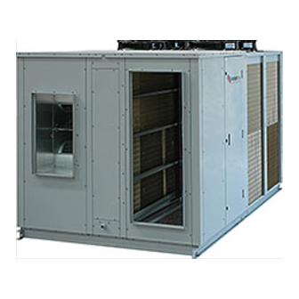
OPA 1370RKTMG01-PZ
Packaged Reverse Cycle R410A
Air Cooled Air Conditioner
GENERAL
This OPA 1370RKTMG Outdoor Unit must
be installed in accordance with all national
and local safety codes.
OPTION
1. TZT-100 Room Temperature Controller
(field fitted).
2. Viking Controller for Economiser with
enthalpy control (factory fitted).
REFRIGERATION SYSTEM
General
The OPA 1370 has four independent
refrigeration circuits and four compressors
to provide the flexibility and economy of
four stage operation, i.e. utilising one to
four circuits as conditions vary, plus the
advantage of staggered starting.
Each refrigeration system has been
charged with HFC-410A (R410A)
refrigerant; refer wiring diagram
specification table for amount. Tapping
points are provided to measure discharge
and suction operating pressures.
Compressors
The compressors are directional scroll
type. One of the four compressors is digital
scroll type. This has a variable capacity
ability that enables closer control of room
temperature.
The compressor lubricant is polyol ester
oil (POE). Note, this oil absorbs moisture
quickly if exposed to open air. On
commissioning, the compressors must be
checked for correct rotation (refer Start
Up Procedure). A time delay prevents
simultaneous starting of the compressors.
ECONOMISER
The economiser fresh air intake cowl with
water separator is supplied separately and
is best fitted after the OPA is mounted on
it's platform. Fitting instructions are supplied
with the cowl.
Controls may be supplied by others. If the
outdoor air temperature or heat content
preferably, is below that of the return air
the fresh air damper opens and the return
air damper closes to provide the first stage
of cooling. A spill air facility in the building
may be necessary for when the return air
damper is closed. The fresh air damper
should return to minimum setting and the
return air damper open before compressors
are allowed to operate to provide further
cooling.
INSTALLATION
Positioning
Refer to dimension diagrams for minimum
clearances. If multiple units are to be
placed side-by-side then allow at least 2 m
between coil faces.
(Digital c/w Plug fan and Economiser)
Mounting
The unit should be fastened to a firm flat
horizontal base using the holes supplied in
the mounting channels.
When the unit is being installed on a roof
it is recommended that the unit is installed
on a substantial structure with anti-vibration
mounts or pads.
Flexible duct connections are recommended
between the supply and return ducts and
the unit.
Condensate Drain
The condensate drain should be 'U' trapped
outside the unit. The trap should have a
vertical height of at least 100 mm. The drain
should have a slope of at least 1 in 50 and
must not be piped to a level above the unit
drain pipe.
VENT PIPE
100 mm
FOR LONG
APPROX.
CONDENSATE
DRAIN RUNS
100 mm
MINIMUM
200 mm
APPROX.
OPEN
DRAIN
'U' TRAP
Electrical Requirements
Electrical work must be done by a qualified
electrician. The outdoor unit must be wired
directly from a distribution board by means
of a circuit breaker or H.R.C. fuse, and a
mains isolator provided - preferably close to
the unit.
Note: DO NOT USE REWIRABLE FUSES.
The OPA 1370 is provided with a 24V AC
control circuit for a thermostat, on/off switch
and/or time clock.
Standard units are suitable for use with
thermostats with either manual Heat/Cool
selection or automatic changeover subject to
the contact ratings of the thermostats.
The system is set up for the compressors to
be controlled variably by:
1. TZT-100 Controller (via RS485 modbus),
2. 0-10V dc command via BMS modbus, or
3. 0-10V dc command via a client supplied
external controller.
If option 1 is chosen, then disconnect or
remove the Signal Input for Controller 0-10V.
If a TZT-100 Controller is used then variable
capacity control is automatically included
and no additional wiring is required.
A 24 hour power supply to the control circuit
is required, otherwise the warranty is void.
SETTING SUPPLY AIR FLOW
Consult OPA 1370 Technical Data pamphlet
at www.temperzone.biz for details of airflow/
duct static pressure, if required.
Installation &
If the indoor air returning to the unit is
regularly expected to be above 50%RH,
then the coil face velocity should be limited
to be 2.5 m/s or less (refer Air Handling
graph in Technical Data pamphlet).
High humidity levels can occur in tropical or
subtropical conditions, and/or when heavily
moisture laden fresh air is introduced.
Select a fan speed that avoids water carry-
over problems.
INDOOR FAN SPEED
The fan speed is continuously variable
via the 0-10V DC control signal applied
between terminals 'FAN GND' and '0–10V'.
Once the maximum design air flow has
been set, a variable fan speed can be
controlled as follows by applying an external
variable 0–10V DC control voltage to
'0–10V' terminal. Connect 0V reference to
'FAN GND'.
CHECK TESTS
1. Check that all the shipping bolts on the
MINIMUM
back of the compressor frame have been
SLOPE
20 mm PER m
removed and that the compressor is
(1 IN 50)
secure on its mounts.
2. Check by hand that all fan motors can
turn freely.
3. Check that the air filters have been
correctly installed, if fitted.
4. Check air diffuser dampers are open if
appropriate.
5. Check that the thermostat, or external
24V controller, is correctly wired to
the unit and is set at the desired
temperature.
6. Check the tightness of all electrical
connections.
7. Leave the thermostat, or external 24V
controller, in the off position and close
the mains isolating switch. (A four hour
delay period is required to allow the
crankcase heater to drive any liquid
refrigerant out of the compressor oil.)
8. Check the supply voltage between each
phase and neutral.
START UP PROCEDURE
After the four hour delay for the crankcase
heater has expired, use the supplied
Commissioning Sheet (Form NS 228) to
record results when completing the following
'Start-up' procedure. A UC6 Service
Interface tool is supplied to read, pressures,
superheat and its set-point, compressor
amps etc.
1. Select a sensible Fan speed (or Auto
Fan mode), operating cycle (cool or
heat), and room temperature set point,
depending on the time of year, such that
the compressor will start and run at a
high capacity.
2. Turn ON the thermostat / external
controller. Wait for the compressor to
Advertisement
Table of Contents

Related Manuals for TemperZone OPA 1370RKTMG01-PZ


Summary of Contents for TemperZone OPA 1370RKTMG01-PZ
- Page 1 Consult OPA 1370 Technical Data pamphlet high capacity. clearances. If multiple units are to be at www.temperzone.biz for details of airflow/ 2. Turn ON the thermostat / external placed side-by-side then allow at least 2 m duct static pressure, if required.
- Page 2 Certified data is damage to prevent corrosion. 2. Check condensate drain for free available on request. drainage. DIMENSIONS (mm) OPA 1370RKTMG-PZ OPA 1370RKTMG01-PZ – Horizontal Supply & Return Air PROJECTION 1000 MIN. CLEARANCE Not to Scale FILTER ACCESS PANEL OUTDOOR...
- Page 3 OPA 1370RKTMG-P – Wiring Diagram Part 1, of 3 CP2W1 CP2W3 CP2W2 CP2W4...
- Page 4 OPA 1370RKTMG-P – Wiring Diagram Part 2, of 3...
- Page 5 OPA 1370RKTMG-P – Wiring Diagram Part 3, of 3 02/19 Pamphlet No. 3986 © temperzone limited 2019...
Need help?
Do you have a question about the OPA 1370RKTMG01-PZ and is the answer not in the manual?
Questions and answers