Table of Contents
Advertisement
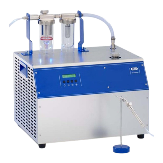
Elmaflame 300
Hydrogen Soldering and Welding Unit
Elma Order No
Elmaflame 300 (230 V)
Elmaflame units generate a mixture of hydrogen and oxygen from demineralized water in an electrolytic process.
After further processing the mixture burns without residues in a micro flame.
Temperature and energy of the micro flame can be adjusted individually to each soldering or welding job by selec-
ting the suitable nozzle size and the type of vapourizer liquid. The high temperature gradient of the micro flame
allows operation of the unit in close proximity of temperature-sensitive components.
Elmaflame units are equipped with a specialized part on the top. Due to the special conduction of the gas, opera-
tion, maintenance and functional checks are easy to do; also, the forming of condensate inside the unit is preven-
ted which increases the reliability and prolongs the service life of the units considerably.
The units are very safe to operate because gas is produced only when it is required. When the burner valve is
closed, the production of gas is automatically shut down, too. Due to the extraordinarily low power consumption
and the low cost of operating media (distilled water, vapourizer liquid) the operating costs of these units are kept
extremely low compared to other units.
The Elmaflame units are fitted with a quick analogous pressure control device so that working on a number of
different jobs and workplaces with one unit is no problem. The operating pressure is variable and the set pressure
keeps precisely at the required level even under changing ambient conditions.
Additional advantages:
• High-level safety standard in compliance with DIN 32508
• Hydrogen-oxygen mixture burns clean without residues
• Easy operation, microprocessor-controlled with integrated leak detector
• Single or multi workplace operation possible
• Quick regulation of the precise operating pressure, automatic adjustment
• LED lighting for functional check and filling level monitoring of vapourizer liquid
• Almost no operating sound due to the temperature-controlled cooling device („whispering cooling")
• Housing and gas reactor made of high-quality stainless steel
• Low operating costs
• Exchange of electrolyte is not necessary over many years
• Any losses of liquid during operation is compensated by refilling distilled water
• No mineral mineral wool padding required for the drying of the gas
Technical data
Mains voltage (V)
Power consumption (W)
Max. gas production (I/h)
Mains fuse (A)
102 3372
pictured Elmaflame 300
230
Max. nozzle size
2000
Work places
Unit outer dimensions w/d/h (mm)
300
16
Gewicht (kg)
product profile
G15 / 1,8 mm
1-8 (1 - G15 / 8 - G26)
515 / 375 / 515
49
Advertisement
Table of Contents

Subscribe to Our Youtube Channel
Summary of Contents for Elma Elmaflame 140
- Page 1 Elmaflame 300 Hydrogen Soldering and Welding Unit Elma Order No Elmaflame 300 (230 V) 102 3372 pictured Elmaflame 300 Elmaflame units generate a mixture of hydrogen and oxygen from demineralized water in an electrolytic process. After further processing the mixture burns without residues in a micro flame.
- Page 2 For filling the Elmaflame unit read and observe the operating instructions. Vapourizer liquid If the vapourizer liquids elma flux or elma redux are not available, fill methylated spirit or IPA into the vapourizer glass instead. For the soldering of platinum you can use distilled water in the vapourizer glass.
- Page 3 Operating Instructions Elmaflame 140 240 300 Hydrogen Soldering Units English Carefully read before operation!
-
Page 4: Table Of Contents
Refilling of distilled water into the reactor .....29 8.1.2 Refilling of vapourizer liquid .........30 8.1.3 Cleaning of the vapourizer glass ......31 8.1.4 Cleaning of the dryer glass........32 8.1.5 Exchange of the filter cartridge in the dryer glass 33 BA/Elmaflame/GB/1107 © Elma GmbH & Co KG... - Page 5 Spare Parts ..............40 Putting out of operation and waste disposal ..... 41 Waste disposal of Elmaflame unit.......41 Waste disposal of electrolyte ........41 Waste disposal of vapourizer liquid ......41 Manufacturer’s contact address ......42 © Elma GmbH & Co KG BA/Elmaflame/GB/1107...
-
Page 6: General
In case of a malfunctioning please contact your supplier or the manufacturer. The unit must be opened by authorized and specialized staff only! BA/Elmaflame/GB/1107 © Elma GmbH & Co KG... - Page 7 Avoid inhaling the vapours! Do not eat, drink or smoke while handling the vapourizer liquid! Wear goggles and gloves! The Elma vapourizer liquid elma redux is not toxic. When using other, methanol-containing vapourizer liquids, take into consideration that these substances may be highly toxic! Read and observe the relevant instructions on the labels of the products used.
-
Page 8: Description Of Operational Process
3 speed ranges which are controlled electronically. Economic efficiency The extremely low energy consumption and the low cost of consumption goods (distilled water, vapourizer liquid) ensure extraordinarily low operating costs compared to other procedures. BA/Elmaflame/GB/1107 © Elma GmbH & Co KG... -
Page 9: Product Description
• Change of electrolyte not necessary over many years. Any losses of liquid due to operational processes are compensated by refilling distilled water. • No mineral wool padding necessary for drying the gas. © Elma GmbH & Co KG BA/Elmaflame/GB/1107... -
Page 10: Safety Devices
(i.e. when the valve at the burner hand piece is open). CE conformity The present Elma hydrogen soldering unit is in compliance with all relevant CE marking criteria. The declaration of conformity can be obtained from the manufacturer. -
Page 11: Delivery Volume
• 1 pair of disposable rubber gloves • goggles • Operating Instructions • packing and transport box (reusable, please store for possible future transportation, e.g. for service or repair return shipment) © Elma GmbH & Co KG BA/Elmaflame/GB/1107... -
Page 12: Description Of Unit Components
Moveable for an easy removal of the glasses. Handles (on both sides) Operating panel with display and operating keys Ventilation openings (on both sides) Burner hand piece Holder for burner hand piece BA/Elmaflame/GB/1107 © Elma GmbH & Co KG... -
Page 13: Description Of Unit Top Part
Glass container for condensate separator (also termed dryer glass) with filter piece. Glass container for vapourizer liquid (also termed vapourizer glass) with sintered cone. LED lighting of vapourizer liquid, for checking the gas flow. © Elma GmbH & Co KG BA/Elmaflame/GB/1107... -
Page 14: Description Of Unit Back
Top line – section on the left: indicates the actual value (mbar) inside the unit. Top line – section on the right: indicates the actual reactor power which is required to produce the set gas pressure. BA/Elmaflame/GB/1107 © Elma GmbH & Co KG... - Page 15 The optimum on new or newly serviced units is 100%. At 0% the Elmaflame must be serviced by an authorized service company. D / E Selector keys for changing and indicating the unit settings. © Elma GmbH & Co KG BA/Elmaflame/GB/1107...
-
Page 16: Preparatory Measures For Initial Operation
Allowed relative humidity of air during operation: max. 80 % • Indoor operation only (no operation in the open) • Protect the unit from direct or indirect heat sources (e.g. heating elements, direct sunlight) to avoid overheating. BA/Elmaflame/GB/1107 © Elma GmbH & Co KG... -
Page 17: Mounting Of The Unit Top Part
4. Connect the gas hose of the burner hand piece to the outlet on the top part (C). The unit top part is movable to facilitate the removal of the glass containers. © Elma GmbH & Co KG BA/Elmaflame/GB/1107... -
Page 18: Filling Of The Reactor With Electrolyte Solution
Prescription on the Use the following substances only: production of • Potassium hydroxide (cookies or flakes – free of water): electrolyte KOH quality: KOH must be contaminated with max. 1.5% potassium carbonate. • Distilled water BA/Elmaflame/GB/1107 © Elma GmbH & Co KG... - Page 19 The glass floating body remains in the filling duct for future filling level checks. 5. Screw the closing cap back onto the filling duct and tighten 6. The filling process is now finished. © Elma GmbH & Co KG BA/Elmaflame/GB/1107...
-
Page 20: Filling Of The Vapourizer Glass With Vapourizer Liquid
We recommend the use of elma redux (Elma Order No. 580 000 9886)as vapourizer liquid. Unlike other methanol- containing liquids elma redux is not toxic. Another... - Page 21 3. Carefully fill vapourizer liquid into the vapourizer glass up to the red maximum filling level marking (see illustration 5.4.B.). 4. Screw the closing cap back onto the filling opening and tighten. 5. The filling process is now finished. © Elma GmbH & Co KG BA/Elmaflame/GB/1107...
-
Page 22: Connecting The Unit To The Mains
2 phases (120 V); 1 N; 1 PE protective conductor EF 240 and EF 300 in 120 V mains Illustration 5.5. Mains requirements for Elmaflame units EF 240 and EF 300 in 120 V mains. BA/Elmaflame/GB/1107 © Elma GmbH & Co KG... -
Page 23: Setting Of Operating Language In The Display
Switch off the unit Switch off the unit by pressing the on/off key at the operating panel*. *The unit programme offers to carry out the required leak check only after restart of the unit. © Elma GmbH & Co KG BA/Elmaflame/GB/1107... -
Page 24: Initial Operation
(OK) at the operating panel. The Elmaflame unit now starts carrying out an automatic leak check. Please wait until the display indicates the result of the leak check. This takes approx. 25 to 30 seconds! BA/Elmaflame/GB/1107 © Elma GmbH & Co KG... -
Page 25: Selection Of The Burner Nozzle
The Elmaflame units are delivered with a selection of nozzles of different sizes. Allowed nozzle sizes Elmaflame 140: 0.5 mm (G25) – 1.0 mm (G19) Elmaflame 240: 0.5 mm (G25) – 1.5 mm (G17) Elmaflame 300: 0.5 mm (G25) – 1.8 mm (G15) The use of larger nozzles is not allowed. -
Page 26: Adjustment Of The Gas Pressure At The Operating Panel
The flame becomes „harder“ with increasing gas pressure, and „softer“ with decreasing gas pressure. The Elmaflame unit allows the perfect adjustment of the flame to each soldering or welding job. BA/Elmaflame/GB/1107 © Elma GmbH & Co KG... -
Page 27: Regulation Of The Burner Flame At The Burner Hand Piece
Do not control the burner flame down until the flame touches the nozzle tip, as this may damage the nozzle. Illustration 6.6. Regulation of the flame size at the burner hand piece valve © Elma GmbH & Co KG BA/Elmaflame/GB/1107... -
Page 28: Operating Stops
Blow out the flame. Procedure B Immerse the flame up to the burner tip into a glass of water for a short period of time. When the flame is extinguished shut the burner hand piece valve! BA/Elmaflame/GB/1107 © Elma GmbH & Co KG... -
Page 29: Technical Details
1.1 (G19) 1.5 (G17) 1.8 (G15) Workplaces Unit outer dimensions W / D / H 395 / 275 / 445 515 / 375 / 515 515 / 375 / 515 (mm) Weight (kg) © Elma GmbH & Co KG BA/Elmaflame/GB/1107... -
Page 30: Maintenance And Repair
Risk of ignition of the flammable liquids contained in the unit, and of the flammable liquids used for filling, due to ignition sources in the vicinity of the unit! Keep the open vapourizer glass container and the vapourizer liquid away from ignition sources! BA/Elmaflame/GB/1107 © Elma GmbH & Co KG... -
Page 31: Refilling Of Distilled Water Into The Reactor
6. For this put the funnel (delivered with the unit) onto the filling duct and carefully fill distilled water until the upper edge of the glass floating body is level with the upper edge of the filling duct (see illustration 5.3.B). © Elma GmbH & Co KG BA/Elmaflame/GB/1107... -
Page 32: Refilling Of Vapourizer Liquid
(illustration 8.1.3.G.). After switch-on and build-up of the operating pressure the vapourizer liquid that has been sucked into the compensation tank is pressed back into the vapourizer glass. BA/Elmaflame/GB/1107 © Elma GmbH & Co KG... -
Page 33: Cleaning Of The Vapourizer Glass
2. Unscrew the fastening ring by turning it to the left (see illustration 8.1.3.D.). 3. Remove the vapourizer glass. Move the complete top part sideways to facilitate removal of the vapourizer glass. © Elma GmbH & Co KG BA/Elmaflame/GB/1107... -
Page 34: Cleaning Of The Dryer Glass
3. Remove the dryer glass. Move the complete top part sideways to facilitate removal of the dryer glass. 4. Clean the glass as described above. 5. Remount the dryer glass by screwing the fastening ring back to the right (see illustration 8.1.3.E.). BA/Elmaflame/GB/1107 © Elma GmbH & Co KG... -
Page 35: Exchange Of The Filter Cartridge In The Dryer Glass
Please contact your supplier or the manufacturer. Caution: The manufacturer cannot be held liable for any damage on persons, or for damage on the equipment © Elma GmbH & Co KG BA/Elmaflame/GB/1107... -
Page 36: Malfunctions And Warnings
Faulty pressure control! Switch off the unit at the mains switch and restart it. If the malfunction is repeated please contact your supplier or the manufacturer of the unit. BA/Elmaflame/GB/1107 © Elma GmbH & Co KG... -
Page 37: Trouble Shooting
• filter cartridge (illustration pressure value. 8.1.3.B.) and/or • sintered cone in vapourizer glass (illustration 5.4.C.) and/or • backfire protection (illustration 4.6.B.) and/or • handle of burner hand piece © Elma GmbH & Co KG BA/Elmaflame/GB/1107... - Page 38 Faulty pressure control The pressure rises above Faulty pressure control and safety Immediately switch off the unit 300 mbar. pressure monitor. and contact your supplier or the manufacturer. BA/Elmaflame/GB/1107 © Elma GmbH & Co KG...
-
Page 39: Repair
Pack and ship the unit in the original packing box. Transportation to or When filled the unit must be transported in upright position only. from the workplace When the filled unit is tilted, it may be damaged considerably! © Elma GmbH & Co KG BA/Elmaflame/GB/1107... -
Page 40: Removal Of Electrolyte
5. Fill the electrolyte into a specially marked and alkaline- resistant tank and store out of reach of unauthorized persons, in particular of children. Or dispose of the electrolyte as described in section 9.2. BA/Elmaflame/GB/1107 © Elma GmbH & Co KG... -
Page 41: Removal Of Vapourizer Liquid
Or dispose of the electrolyte as described in section 9.2. 5. Remount the vapourizer glass by screwing the fastening ring back to the right (see illustration 8.1.3.E.). © Elma GmbH & Co KG BA/Elmaflame/GB/1107... -
Page 43: Putting Out Of Operation And Waste Disposal
Do not let escape into the sewerage system / surface water / groundwater. Do not let escape into the soil. Do not let escape into the environment uncontrolled. Containers can also be returned free of charge when they are completely empty. © Elma GmbH & Co KG BA/Elmaflame/GB/1107...
Need help?
Do you have a question about the Elmaflame 140 and is the answer not in the manual?
Questions and answers