
Subscribe to Our Youtube Channel
Related Manuals for Dekker DVW Series

Summary of Contents for Dekker DVW Series
- Page 1 Operation Manual DEKKER Controller Programmable Logic Controller (PLC) Part No. 9983-0000-E02 / September 2019...
-
Page 2: Table Of Contents
CHANGING VACUUM CUTIN AND CUTOUT MULTIMACHINE SETUP TEMPERATURE WARNINGS AND FAULTS SETTING DATE AND TIME ENTERING KEYCODES COOLING FAN ROTATION MANUAL ROTATION SCAVENGER OUTPUT FAULTS AND FAULT LOG AUTOSTART MAINTENANCE SCHEDULES DEKKER Vacuum Technologies, Inc. / Part No. 9983-0000-E02 / September 2019... - Page 3 RESETTING MAINTENANCE SCHEDULE HOURS DP INLET REMOTE START STOP NETWORK OPTIONS DEKKER Vacuum Technologies, Inc. / Part No. 9983-0000-E02 / September 2019...
-
Page 4: Customer Service
Parts should be purchased from the nearest authorized DEKKER Vacuum Technologies, Inc. (hereafter referred to as DEKKER) representative (visit www.dekkervacuum.com to find a distributor near you via the Distributor Locator) or from the vacuum pump system supplier. If, for any reason parts, cannot be obtained in this manner, contact the factory directly. -
Page 5: Introduction
INTRODUCTION The Dekker Controller provides for system control as well as monitoring of system status. Service functions include display of spare parts list, maintenance schedules, service history, and logging of fault conditions. The Dekker Controller includes a 4-line large-font LCD (Liquid Crystal Display), a durable Lexan membrane keypad, and multiple status LEDs. -
Page 6: Battery
ESCAPE button (ESC) is used to return to the Run/Standby/Stopped screen. BATTERY The Dekker Controller may be shipped with a battery protector placed between the battery clip and the surface of the battery, it may be a rubber sleeve around the clip or a small plastic insulator between the clip and battery. -
Page 7: Controler Input/Output Layout
CONTROLER INPUT/OUTPUT LAYOUT DEKKER Vacuum Technologies, Inc. / Part No. 9983-0000-E02 / September 2019... -
Page 8: Current Input/Output Assignments
C1/NO = Vac Pump Motor Starter C2/NO = Local Lag Light C3/NO = Horn Output C4/NO = Remote Lag Light C5/NO = All Fault Out C6/NO = Scavenger Valve Out C7/NO = Cooling Fan DEKKER Vacuum Technologies, Inc. / Part No. 9983-0000-E02 / September 2019... -
Page 9: Entering Password
To restore Basic Access, press and hold the ESCAPE (ESC) button for two seconds. The screen will display the words Access Locked. Basic Access is also restored upon powering the controller off and on. If the DEKKER Controller has no activity (no buttons pushed) for 5 minutes, it will default back to Basic Access. -
Page 10: Changing Vacuum Units
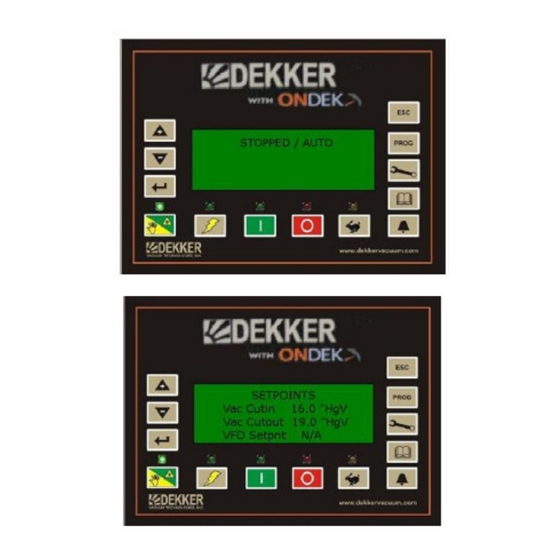
If the system is STOPPED or RUNNING press the PROG button once to view the Setpoints screen. If HgV is already set for vacuum units, you will see VAC CUTIN and VAC CUTOUTt in HgV units. DEKKER Vacuum Technologies, Inc. / Part No. 9983-0000-E02 / September 2019... - Page 11 To change to another type of unit, use the DOWN arrow to scroll to Vacuum Unit then press ENTER. Using the UP arrow to change unit, you will have a choice of TORR, HgV or Millibars. Once selection is made, press ENTER to save. DEKKER Vacuum Technologies, Inc. / Part No. 9983-0000-E02 / September 2019...
-
Page 12: Changing Vacuum Cutin And Cutout
Press the UP or DOWN button if necessary to select VAC CUTIN then press ENTER. Once ENTER is pressed, use UP or DOWN arrows to change the value and then press ENTER to save. Repeat for VAC CUTOUT. DEKKER Vacuum Technologies, Inc. / Part No. 9983-0000-E02 / September 2019... -
Page 13: Multimachine Setup
• • & TEMPERATURE WARNINGS AND FAULTS Temperature warnings and faults are factory set, It is not recommended to change these settings without consulting with a Dekker Service Technician. DEKKER Vacuum Technologies, Inc. / Part No. 9983-0000-E02 / September 2019... -
Page 14: Setting Date And Time
Use UP and DOWN arrows to change Date, press ENTER to save. Use UP and DOWN arrows to scroll to the Time and press ENTER Use UP and DOWN arrows to change Date, press ENTER to save. DEKKER Vacuum Technologies, Inc. / Part No. 9983-0000-E02 / September 2019... -
Page 15: Entering Keycodes
Low Level Switch 001146833 Temperature Switch 001117934 Vacuum Switch 001134688 Auxiliary RTD Temperature 001182214 Differential Pressure Inlet Filter 001114236 Back Pressure Transducer 001196511 Multimachine 001127744 Remote Start/Stop 001169856 Cooling Fan 001149877 DEKKER Vacuum Technologies, Inc. / Part No. 9983-0000-E02 / September 2019... -
Page 16: Cooling Fan
COOLING FAN The Dekker Controller is equipped with a temperature control to operate a cooling fan when applicable. This feature requires a cooling fan keycode to be entered (see entering keycodes above). Once the cooling fan keycode is entered press the PROG button until you see the SETPOINT screen. -
Page 17: Rotation
“Manual Transfer” appear on the screen, then release the button. Wait a few seconds and you will see the upper text “LD” move to the opposite controller, the text “LG1” will move to where the “LD” was previously. DEKKER Vacuum Technologies, Inc. / Part No. 9983-0000-E02 / September 2019... -
Page 18: Scavenger Output
Output 6 on the controller is used for a bleed valve. This output cycles on for 30 Secs and off for 9 minutes based on vacuum level. The vacuum level for cycling to occur is adjustable via the Setpoint menu on the Dekker Controller. -
Page 19: Faults And Fault Log
Temperature and in some versions of firmware Back Pressure. The Temperature and Back Pressure faults are adjustable from the setpoint screen, but it is not recommended to change these without consulting with a Dekker Technician. Changing these values could result in pump damage. Below is what is shown on the screen when a temperature fault occurs. -
Page 20: Autostart
AUTOSTART The Dekker controller is equipped with Autostart. This feature allows automatic restart of system when power returns from a power loss. To enable this feature press PROG button to show SETPOINTS screen. Use DOWN arrow to select Autostart. Press ENTER. Use UP arrow to change to ON. Press ENTER to save. If system is multimachine, this must be set on all controllers. -
Page 21: Maintenance Schedules
MAINTENANCE SCHEDULES Pressing the MAINT button once will display the screen below: This screen shows the support phone number for Dekker Vacuum along with the Serial number and model number of the system. Pressing the MAINT button twice will display the spare parts list for the system. This list can be used for ordering parts if needed. - Page 22 The time in hours until the maintenance is due counts down and can be seen on the Dekker Controller LCD in this area. Proper maintenance is necessary to provide proper performance and can prolong the life of your system. The UP and DOWN ARROW buttons can be used to navigate through the list.
- Page 23 Pressing MAIN again will return you to the Dekker support screen. Pressing ESC at anytime will return to the main screen. DEKKER Vacuum Technologies, Inc. / Part No. 9983-0000-E02 / September 2019...
-
Page 24: Resetting Maintenance Schedule Hours
ENTER also records the date and time this service was completed in the Service History log.. Pressing ESC will take you back to the main screen and the warning will be gone. Note: warnings and faults only show in run mode. DEKKER Vacuum Technologies, Inc. / Part No. 9983-0000-E02 / September 2019... -
Page 25: Dp Inlet
Digital input 6 on the other side. A NC momentary button is wired to +24VDC on one side and to Digital input 7 on the other. Both buttons must be momentary. Then to enable Remote Start/Stop you must enter the keycode. (See Entering Keycodes) DEKKER Vacuum Technologies, Inc. / Part No. 9983-0000-E02 / September 2019... -
Page 26: Network Options
Gateway for network use. You can also turn DHCP on if a DHCP server is available to assign the controller an IP address. This screen should only be changed by qualified personnel. DEKKER Vacuum Technologies, Inc. / Part No. 9983-0000-E02 / September 2019...
Need help?
Do you have a question about the DVW Series and is the answer not in the manual?
Questions and answers