Table of Contents
Advertisement
Quick Links
Operating Instructions
Control Unit
PRIMUS+
We reserve the right to change the contents
due to product innovation or technical im-
provement.
Please state type of equipment and serial
number when contacting us.
Please read these instructions and keep the
manual safe!
Please observe and follow the safety notes!
Sesotec GmbH
Regener Straße 130
Telephone: +49 (0) 8554 308-0 * Fax: +49 (0) 8554 2606
E-mail: info@sesotec.com
Internet: http://www.sesotec.com
Service: Telephone: +49 (0) 8554 308-180
* D-94513 Schönberg
1
PRIMUS-PLUS-BA-CU-EN-5136.docx
Advertisement
Table of Contents

Subscribe to Our Youtube Channel
Related Manuals for SESOTEC PRIMUS+

Summary of Contents for SESOTEC PRIMUS+
- Page 1 Please read these instructions and keep the manual safe! Please observe and follow the safety notes! Sesotec GmbH Regener Straße 130 * D-94513 Schönberg Telephone: +49 (0) 8554 308-0 * Fax: +49 (0) 8554 2606 E-mail: info@sesotec.com Internet: http://www.sesotec.com...
- Page 2 Manufacturer: Sesotec GmbH D-94513 Schönberg, Germany Contact: Sesotec GmbH Regener Straße 130 D-94513 Schönberg, Germany Tel.: +49 (0) 8554 3080 Fax.: +49 (0) 8554 2606 E-mail: info@sesotec.com Internet: www.sesotec.com Represented by: PRIMUS-PLUS-BA-CU-EN-5136.docx...
-
Page 3: Table Of Contents
Contents Contents General information Introduction Field of application Application reasons System identification Symbols used EC DECLARATION OF CONFORMITY Overview Design and method of operation Functional principle Functional and control elements 2.2.1 Operating module with LCD graphic display 2.2.2 Cable glands 2.2.3 PRIMUS+ / IO electronics board 2.2.4... - Page 4 Contents Quick Start 6.2.1 Language Selection Menu Structure 6.3.1 Main menu 6.3.2 Function menu items 6.3.3 Settings menu items 6.3.4 Output menu 6.3.5 Setup menu 6.3.6 Operating mask 6.3.7 Change product 6.3.8 Auto-Set 6.3.9 Product parameter 6.3.10 Conveying speed 6.3.11 Output 6.3.11.1 Output adjust 6.3.11.2...
- Page 5 Contents Replacement of electronic boards 7.4.1 Replacing the CU electronics board PRIMUS+ 7.4.2 Replacing the IO electronics board PRIMUS+ 7.4.3 Replacing the display board Maintenance and cleaning Maintenance Cleaning 8.2.1 Hints for cleaning 8.2.2 Cleaning instructions 8.2.3 Care advice for stainless steel Spare parts Spare parts view Spare parts list...
-
Page 6: General Information
1.2 Field of application The PRIMUS+ control unit is used in combination with Sesotec metal detectors and separators in the plastics, wood, food, chemical, and in a special version also in the pharmaceutical industry. Depending on the respective version, these systems inspect packed, unpacked, or piece products, and bulk mate- rials for magnetic and non-magnetic metal contaminations. -
Page 7: Overview
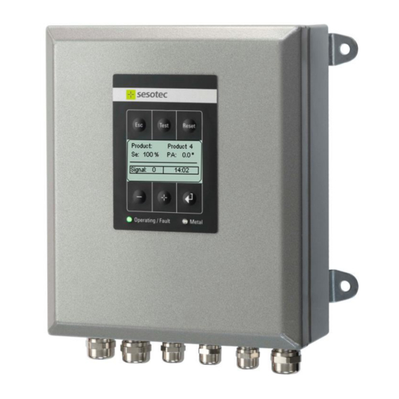
1. General information 1.7 Overview PRIMUS+ Control Unit Graphic display... -
Page 8: Design And Method Of Operation
2. Design and method of operation Design and method of operation 2.1 Functional principle Detection coil Control Unit PRIMUS+ IO electronics CU electronics Analog/digital Power Signal amplifier supply converter Oscillator Memory for Relay 10 products I/O interface Control panel LCD graphic Logbook display Monitoring... -
Page 9: Functional And Control Elements
2. Design and method of operation 2.2 Functional and control elements 2.2.1 Operating module with LCD graphic display 1 Graphic display LCD module Display of operating and input masks 2 Operator keys + , - , , Esc For operation and machine setting 3 Function key Reset Reset to restore the unit after metal or fault signal... -
Page 10: Primus+ / Io Electronics Board
2. Design and method of operation 2.2.3 PRIMUS+ / IO electronics board (GND) (GND_24V) LD12 LD11 LD10 2 4 6 JP10 1 1 3 5 25 26 27 28 29 30 31 32 O1 O2 17 18 19 20 21 22 23 24 Connectors and termi- (1) "Mains/Option"... - Page 11 2. Design and method of operation Jumper: (6) "MV connection monitor" JP10, 1-2, MV1 JP10, 3-4, MV2 JP10, 5-6, MV3 (11) "MV voltage supply" JP3, 2-1 external 24V (connector J13 +/-) JP3, 2-3 internal, 24V (default) (15) "Service jumper" J8, 5-6, plugged, enable, program update Test points: (8) "GND_24V”...
-
Page 12: Primus+ / Cu Electronics Board
2. Design and method of operation 2.2.4 PRIMUS+ / CU electronics board Connectors and terminals: "Receiver" J10, input signal from the detection coil "Transmitter" J7, output signal to the detection coil "Service interface" J11, diagnostics interface (11) "FFC connector" J5, ribbon cable connector to the display module (12) "Memory"... -
Page 13: Dimensions And Technical Data
3. Dimensions and technical data Dimensions and technical data 3.1 Technical data sheet, see annex 3.2 Supply connections, see technical data sheet in the annex 3.3 Environmental conditions for operation, storage, and transport The environment of the control unit should be free of any chemical vapours such as softeners, chlo- rine, or similar substances. -
Page 14: Safety
The equipment can be used in the plastics, food, animal feed, recycling, and chemical industry. Basically it is possible to also use the system in other applications than the in- tended use stated herein, but such applications always require the prior consultation and approval of Sesotec GmbH. 4.2 Safety signs Symbol... -
Page 15: Safety Information For Operation, Maintenance And Cleaning
4. Safety detector or separator does not exceed the limits stated in the provisions. Therefore there are no health impairments due to electromagnetic fields in this area for persons and for wearers of medical implants such as cardiac pacemakers. Inside the coil of round or closed tunnel coils, or on the surface of flat coils, the limits may be exceeded depending on design and system version. -
Page 16: Improper Use
4. Safety 4.11 Improper use For other applications as enumerated in 4.1 the control unit PRIMUS+ intended for – that is regarded as inadmissible operation. Improper use also includes operating the equip- ment with excessive mechanical, static or dynamic loads (e.g. heavy machine parts or strong vibration). -
Page 17: Commissioning
(E.g. from contactor controls)! Cable lengths may only be modified after consultation with "Sesotec". Use only original cables. Lay the connecting cable in fixed installation apart from other cables (e.g. fix it with nailing clips or lay it in a cable duct). -
Page 18: Primus+ / Io Electronics Board (Control Electronics Board)
5. Commissioning 5.2.1 PRIMUS+ / IO electronics board (control electronics board) 5.2.2 Electrical connections Pos. Connection Type of connection Function "Mains/Option" Connector for mains L/N: Electronics power supply supply O1/O2: Optional 24V module power supply connector "Relay metal" Voltage free Normal operation: Contacts 71 and 72 closed relay contact... -
Page 19: Primus+ / Cu Electronics Board (Evaluation Electronics Board)
5. Commissioning Pos. Connection Type of connection Function "Jumper JP10" Placement, JP10 Functions connection monitor- Jumper plugged, monitoring inactive ing MV1 – MV3 Jumper open, monitoring active 1 – 2 active / inactive MV1 connection monitoring 3 – 4 MV2 connection monitoring 5 –... -
Page 20: Electrical Performance
5. Commissioning 5.2.4 Electrical performance Potential-free relay contacts 250V 3A with alternating voltage 120V 3A with direct voltage For the potential-free relay circuits fusing must be provided outside the equipment. Switching outputs (MV1, MV2, MV3) Maximum current load: 250 mA Switching outputs (LM, LB, LF, Mz) Maximum current load: 150 mA Switching inputs... -
Page 21: Electrical Connection Of The Equipment
5. Commissioning 5.2.6 Electrical connection of the equipment Cable Maximum cable length for external components, switches and sen- Shield Housing sors is 15 m. Only shielded cables should be used. The shields must be attached directly to the electronics housing. Mains supply via control electronics board 1 Conductor 1 (black) to terminal L... -
Page 22: Behaviour Of Machine At Start Up
5. Commissioning 3. Feed cable into connection box according to diagram below. Make sure that the mains supply is switched off. Use a suitable shutdown unit i.e. emergency switch. Terminal box 3 pin terminal Control unit mains cable Main supply Conductor 1 (black) To terminal L Conductor 2 (black) -
Page 23: Relays - Operating Status
5. Commissioning Output Contact status with parameter "Metal at power on = [x]" LED Operation / Fault "off" LED Metal "on" Metal relay Contacts 71 and 72 closed (consistent with metal alarm) Fault relay Contacts 81 and 82 closed (consistent with fault status) MV1 / MV2 / MV3 switching High active or Low active, depending on system setup outputs... -
Page 24: Menu / Operation Primus
6. Menu / Operation PRIMUS+ Menu / Operation PRIMUS+ This chapter starts with a short manual and cross references in order to familiarise the reader with the most important settings. Following this, all setup menus are described. 6.1 General Operation The control unit can be operated with 4 keys of the membrane keypad. -
Page 25: Quick Start
6. Menu / Operation PRIMUS+ 6.2 Quick Start 6.2.1 Language Selection (If required) 1. Turn on device, operating mask is displayed. 2. Press the key. 3. Press the key until you reach the end of the menu list ("Setup" menu item) and confirm this with the key. -
Page 26: Menu Structure
6. Menu / Operation PRIMUS+ 6.3 Menu Structure Overview of menu items and setting masks, starting from the main menu. 6.3.1 Main menu Menu items: Change product Auto-Set Product parameter Output Conveying speed Setup 6.3.2 Function menu items Product selection: 001: to 010:... -
Page 27: Output Menu
6. Menu / Operation PRIMUS+ 6.3.4 Output menu... -
Page 28: Setup Menu
6. Menu / Operation PRIMUS+ 6.3.5 Setup menu Setup levels There are currently three setup levels. Level 0 -> "Setup level standard" without "Code-No." The following options are available: Logbook Show counter Device-Info Revision Language*) ... - Page 29 6. Menu / Operation PRIMUS+ Overview 1 German Czech English Russian French Greek Italian Swedish Spanish Turkish Dutch Polish Japanese Hungarian...
- Page 30 6. Menu / Operation PRIMUS+ Overview 2 In addition to the standard menu items the following menu items can be selected in setup level 1. Setup level 1, code 1000...
- Page 31 6. Menu / Operation PRIMUS+ Overview 3 In addition to the standard menu items the following menu items can be selected in setup level 2. Setup level 2, code 2000 The PRIMUS+ control unit has two inputs. Depending on the factory settings and function correspond- ing settings can be made in the setup menu for sensor 1 and sensor 2.
-
Page 32: Operating Mask
6. Menu / Operation PRIMUS+ 6.3.6 Operating mask Displayed in normal operation mode. Displayed information: Current product name (top right) Sensitivity (0 - 100%) Product angle (0° - 180°) Info field: Current time, status of outputs etc…. Signal: Current signal of the metal detector Signal value >100 ... -
Page 33: Change Product
6. Menu / Operation PRIMUS+ 6.3.7 Change product - Starting from the operating mask, press the key in the main menu to select the Change product menu item. PRIMUS+ can save up to 10 different products and their corresponding parameters. This functionality enables quick product changes. -
Page 34: Auto-Set
6. Menu / Operation PRIMUS+ 6.3.8 Auto-Set - Starting from the operating mask, press the key in the main menu to select the Auto-Set menu item. - This input mask is displayed, if the menu level is password-protected. Passwords are set by the customer. This function is used to quickly set the metal detector to the properties of a new product or of the op- erating environment. -
Page 35: Product Parameter
6. Menu / Operation PRIMUS+ 6.3.9 Product parameter Starting from the operating mask, press the key to select the Product parameter menu. - In the Product parameter menu the "Sensitivity" and "Product angle" pa- rameters can be further optimised manually. - This input mask is displayed, if the menu level is password-protected. -
Page 36: Output
6. Menu / Operation PRIMUS+ 6.3.11 Output Starting from the operating mask, press the key to select the Output menu. Output menu for setting the outputs MV1/2/3 Output menu and MR1. Output adjust Output lock Use the keys to select individual Monitoring Output Level menu items, and then press... -
Page 37: Output Lock
6. Menu / Operation PRIMUS+ 6.3.11.2 Output lock - Output lock means that after a metal event the outputs are activated for the set delay time, but are not automatically reset. Reset - Resetting must be done by pressing the key. -
Page 38: Output Options
6. Menu / Operation PRIMUS+ 6.3.11.5 Output options In the "Output options" menu several functions can be set for the outputs MV1/2/3, MR1 and LM. These functions have an influence on the masks and settings in other menu items. Switching function in case of metal as set [x] Outputs active ... -
Page 39: Logbook
6. Menu / Operation PRIMUS+ 6.3.12.1 Logbook - Select "Logbook" with - Scroll through the saved incidents with . All incidents are in chronological order and displayed with date and time. - Leave "Logbook" with The logbook contains 100 entries which are permanently saved. The following information is available: ... - Page 40 6. Menu / Operation PRIMUS+ The following messages and information are displayed in the logbook: Type Incident Additional Information Comment Metal Metal - Global metal counter - Metal signal Info Mains on/off Product change - Old Product number - New Product number Change of product data - Current Pd.
-
Page 41: Clear Logbook (Menu Item Requires Login)
6. Menu / Operation PRIMUS+ 6.3.12.2 Clear logbook (Menu item requires login) - Select "Clear logbook" with - Deleting the logbook requires confirmation - Cancel with "no" and retain logbook. - Delete logbook with "yes". 6.3.12.3 Show counter - Select "Show counter" with - Use the keys to select the respective counter, and then press... -
Page 42: Device-Info
6. Menu / Operation PRIMUS+ 6.3.12.4 Device-Info - Select "Device-Info" with The display shows the currently set detection frequency and the currently set operating mode. - Pipe Scan - PROTECTOR - RAPID - Belt conveyor - Vacuum/pressure conveying - C-SCAN DLS Serial number of the CU electronics board Voltage values of the CU electronics board Nominal values... -
Page 43: Change Password (Menu Item Requires Login)
6. Menu / Operation PRIMUS+ 6.3.12.6 Change password (menu item requires login) - Select "Change password" with Available passwords: - Change product for menu „Change product“ - Auto-Set/Product for menu „Auto-Set“ „Product parameters“ „Conveying speed“ - Parameter for menu ... -
Page 44: Setup Options (Menu Item Requires Login)
6.3.12.11 Frequency deviation (menu item requires login) When several Sesotec metal detectors or metal separators with the same search frequency are used near each other, an interference in the signal can occur. To prevent this, a frequency deviation can be selected. -
Page 45: Factory Settings (Menu Item Requires Login)
6. Menu / Operation PRIMUS+ 6.3.12.12 Factory settings (menu item requires login) With this menu item the system can be reset to the factory settings at the time of delivery. System data an all product memories will be reset to factory settings, i.e. to the settings at the time of delivery. -
Page 46: Flap Monitoring (Option) (Menu Item Requires Login)
6. Menu / Operation PRIMUS+ 6.3.12.16 Flap monitoring (option) (menu item requires login) - Select "Flap monitoring" with Flap monitoring can be configured in this menu. 0.0s deactivates the monitoring. Values different to 0 set the time, which the flap may not extend when switching from normal position to reject position and vice versa. -
Page 47: Errors And Error Remedying
Ohm meter: replace if incorrect. necessary or check transmitter frequency. 7.1.4 Transmitter over temperature Possible causes Remedy CU electronics board defective. Replace the CU electronics board. Coil or transmitter connection board defective. Contact Sesotec service. -
Page 48: Hardware Cu
Replace the CU and/or IO electronics board. 7.1.8 Watchdog Possible causes Remedy Software error of the CU electronics board. If this occurs several times, contact Sesotec ser- vice. 7.1.9 Memory error Possible causes Remedy System and product data memory defective. -
Page 49: Air Pressure
7. Errors and error remedying 7.1.12 Air pressure Possible causes Remedy Appears on display if the air pressure monitor re- Check the connection cable to the pressure sen- sponds or the connection to the sensor is inter- sor. rupted. No air pressure or air pipe broken. Check air supply. -
Page 50: External Error
7. Errors and error remedying 7.1.17 External error Possible causes Remedy Error signal at the external error input of the IO Find the cause of the external error and remedy it. electronics board. Alarm message of the frequency inverter. For example: Thermal contact of motor protection. -
Page 51: Replacing The Backup Battery
7. Errors and error remedying 7.3 Replacing the backup battery Because of energised components in the electronics housing there is a risk of injuries due to electric shock or burns. Therefore such work may only be performed by a qualified electrician under strict obser- vation of the attached warning labels and with due regard to standard approved rules of electrical engineering. -
Page 52: Replacement Of Electronic Boards
7. Errors and error remedying 7.4 Replacement of electronic boards The Control-Unit PRIMUS+ consists of the following three boards: CU electronics board (2), IO electronics board (5) and display board (7). 7.4.1 Replacing the CU electronics board PRIMUS+ 1. Disconnect voltage supply and external circuits and open the cover at the electronics housing. 2. -
Page 53: Replacing The Io Electronics Board Primus
7. Errors and error remedying Transferring all settings New controller board Old controller board Procedure: 1. Remove the data memory module from the new (already installed) CU electronics board (a) and place it aside. 2. Remove the data memory module from the old CU electron- ics board (b) and insert it in the memory socket of the new CU electronics board (a). -
Page 54: Maintenance And Cleaning
8. Maintenance and cleaning Maintenance and cleaning Prior to cleaning turn off the system with the master switch and disconnect the system from the mains voltage. 8.1 Maintenance The PRIMUS+ control unit is maintenance-free, yet it is still appropriate to inspect the equipment in regular intervals: ... -
Page 55: Spare Parts
9. Spare parts Spare parts If you should have any questions please state equipment type and serial number! Spare parts and wearing parts must always be obtained from the manufacturer of from a supplier that is certified by the manufacturer. 9.1 Spare parts view... -
Page 56: Spare Parts List
Hexagon nut M4 31160908 Wall mount for control cabinet 08006717 (accessory) Distance bolt M4x15 08023239 IO electronics board PRIMUS+ 77103219 Membrane keypad PRIMUS+ Sesotec 77100328 Membrane keypad PRIMUS+ Neutral 77100326 Display PRIMUS+ 33015460 CU electronics board PRIMUS+ 33015446 AC/DC converter (option) -
Page 57: Shipping, Preservation, Waste Disposal, Transport, Storage
10. Shipping, preservation, waste disposal, transport, storage 10 Shipping, preservation, waste disposal, transport, storage 10.1 Shipping, preservation, waste disposal Choose packing that is suitable for the type and size of unit, taking into account whether the shipment is for export by sea or airfreight, or for national or international road transport The packing material must protect the goods from all damage under normal transport conditions. -
Page 58: Transport
10. Shipping, preservation, waste disposal, transport, storage 10.2 Transport In order to avoid injury or damage to the unit it must be handled properly. In addition to following the instructions below, general health and safety good practice and specific accident prevention guidelines should be observed. -
Page 59: Annex
11. Annex 11 Annex EC DECLARATION OF CONFORMITY Technical data sheet Accessories: UL/CSA certificate...
Need help?
Do you have a question about the PRIMUS+ and is the answer not in the manual?
Questions and answers