Advertisement
Quick Links
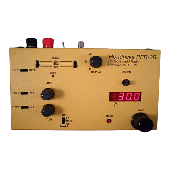
PFR-3B
Portable Field Radio
Figure 1
Specifications:
Bands : 40 meters, 30 meters and 20 meters
Tuning range: Full band coverage
DDS VFO with 50 Hz slow tuning rate and 200 Hz fast tuning rate
Mode: CW only
Receiver MSD: 0.2 uV typical
Selectivity : 300 Hz
Four crystal IF filter and 600 Hz center frequency audio band pass filter
Receive current, no signal typical:
Display on, 47 ma
Display off, 34 ma
Transmitter:
5 watts at 12.0 volts, all bands +/- 10%
Transmitter current: 650 ma (40 M) to 750 ma (20 M) typical at 5 watts.
Spurs: - 50 dBc maximum, all bands
5 to 40 wpm internal B mode iambic keyer
Two (2) 63 character keyer memories.
Coax or balanced line output
Built in SWR indicator and BLT (balanced line tuner)
Size: 7.2" wide X 4.2" deep X 1.5" high (less knob height).
Weight: 18 oz, no batteries installed.
Power supply voltage: 8 volts minimum, 12.5 volts maximum. 12 to 9 volts recommend.
External power or internal battery pack
Pacific Antenna
www.qrpkits.com
Manual Revised: February 24, 2016
Advertisement

Summary of Contents for QRPKits PFR-3B
- Page 1 PFR-3B Portable Field Radio Figure 1 Specifications: Bands : 40 meters, 30 meters and 20 meters Tuning range: Full band coverage DDS VFO with 50 Hz slow tuning rate and 200 Hz fast tuning rate Mode: CW only Receiver MSD: 0.2 uV typical...
-
Page 2: Assembly Notes
● Parts are numbered on the board starting at the lower right hand corner. Numbers run bottom to top, then right to left across the board. ● Missing or lost parts? Contact QRPKITS.com for replacements. - Page 3 Figure 3...
- Page 4 4-40 x 1/4” screws Socket with black plastic caps 5 feet #26 magnet wire #4 lock washers Star washers 12 feet #28 magnet wire 4-40 x 1/4” screws Phillips pan head screws Rubber feet Feet for case Case Yellow case for PFR-3B...
- Page 5 Figure 4: Resistors, diodes, RFCs 10 OHMS BRN/BLK/BLK/GLD 2.2 K RED/RED/RED/GLD 1 MEG BRN/BLK/GRN/GLD 22 K RED/RED/ORG/GLD 2.2 K RED/RED/RED/GLD 2.2 K RED/RED/RED/GLD 10 K BRN/BLK/ORG/GLD 51 OHMS GRN/BRN/BLK/GLD 2.2 K RED/RED/RED/GLD 470 OHMS YEL/VOL/BRN/GLD 2.2 K RED/RED/RED/GLD 1 MEG BRN/BLK/GRN/GLD 2.2 K RED/RED/RED/GLD...
- Page 6 Figure 5: Capacitors Since there are a lot of 0.1 ufd caps, these are highlighted in yellow. The rest of the assorted values are in light blue. We will also install the crystals, highlighted in gray, and are mounted first. Solder a lead clipping from the hole next to the crystal labeled “G”...
- Page 7 Figure 6: Most everything else Table 4: Parts should be installed in the order in which they are listed in the table below. LED Display This will go in only one way as there are two missing pins and corresponding pads.
- Page 8 Figure 7: Parts mounted on bottom of board Several parts mount on the bottom of the board. These are the variable capacitors, the toroid coils, the BFO trimmer and the resetable fuse. Table 5 CV1, 2, 3 Mount these three variable caps to the bottom of the board, using the short screws supplied. BFO trimmer.
- Page 9 Table 6b: L5 and T2 – These mount to the top of the board. 8 turns #28 (5”) on FT37-43, black core 25 turns #28 (15”) on FT37-43, black core. 5 turns #28 (3”) for primary. First wind the 25-turn secondary.
- Page 10 Testing and calibration: The board is now complete except for installing the ICs. Give the BFO trimmer (CT1) about a ¼ turn from its factory setting. If you look closely in the trimmer hole, you will see an arrow at one end of the screwdriver slot.
- Page 11 If you compare the power out between direct and via the BLT, you will notice a few 100 mW loss in power while using the BLT. DDS frequency calibration and precise BFO setting adjustment: If you have an accurate frequency counter, the DDS frequency can be calibrated. Without calibration, the operating frequency maybe off by a few 100 Hz on the 20 meter band and to lesser extent on the lower bands.
- Page 12 Install the power jack, binding posts, DPDT toggle switch and BNC jack to the rear panel. Wire as shown below. Power jack wiring should be routed “the long way” directly across the board from the jack and then along the front edge of the enclosure. Figure 10a Figure 10b Battery holder mounting:...
-
Page 13: Operation
Operation Power supply: The PFR-3B rig should be powered by no more than about 12 volts and no less then 8 volts. Maximum supply current at full transmitter output is typically less than 800 ma. If a 13.8 volt bench supply is used to power the rig, two silicon rectifier diodes should be added in series with the positive supply lead to drop the voltage down closer to 12 volts. - Page 14 headphones so it is wise to turn the volume down before scanning the band. You will also want to keep the volume turned down enough to keep the AGC from activating in the first place. RIT (receiver incremental tuning) Momentarily pushing the Tuning knob for less then 1 second will activate RIT. The display will change to display [ r -0.0 ] The 'r' indicates RIT mode is active and -0.0 shows the displacement from the transmit frequency, up to + or –...
- Page 15 by clicking the MENU switch. Note: DFE mode is not available if RIT is on. Storing a message: Click and release the MENU switch 4 times to enter the Message store mode. The display will show [ --. ] and the letter “M”...
- Page 16 the BLT and one side of the BLT output winding is grounded. Note: The handle of the switch on the rear panel should be facing towards the coax jack when using either ● a balanced line on the binding posts or a coax feed antenna which is not using the tuner. Using the BLT: Learning to use the tuner takes some practice.
- Page 17 Troubleshooting: More often then not, any trouble with the board not working is inevitably tracked down to soldering issues, so this is the first thing to look for. Looking at the solder pads at the TOP of the board can be helpful. If the hole around a part lead isn't full of solder, it probably isn't soldered on the bottom.
- Page 19 Schematics pg1...
- Page 20 Schematics pg2...
Need help?
Do you have a question about the PFR-3B and is the answer not in the manual?
Questions and answers