
Related Manuals for KARL KAPS SOM 62 LED

Summary of Contents for KARL KAPS SOM 62 LED
- Page 1 SOM 62/32/22 Karl Kaps GmbH & Co KG Tel. + 49 (0) 6441 / 80704-0 service@kaps-optik.de Schulstrasse 57 35614 Asslar Fax. + 49 (0) 6441 / 85 9 85 www.kaps-optik.de Germany...
-
Page 2: Table Of Contents
Symbols used and what they mean Warning and safety advice Installation instructions Notes for use and disposal Directives, laws and standards Delivery state Deliverables 5.1.1 Deliverables for SOM 62 LED 5.1.2 Deliverables for SOM 32 LED 5.1.3 Deliverables for SOM 22 LED Transportation/packaging/unpacking/checking 5.2.1 Unpacking... - Page 3 15 When faults occur 15.1 Summary of potential faults 16 Technical description 16.1 Technical details 16.2 Dimensions 16.2.1 SOM 62 LED 16.2.2 SOM 32 LED 16.2.3 SOM 22 LED 17 Declaration of conformity 18 Warranties SOM 62/32/22 LED DE 2017-03...
-
Page 4: General
Instructions for use SOM 62/32/22 LED 1 General Thank you for selecting one of our quality products. Kaps devices combine excellent illumination, easy and exact positioning, and very good optical performance in a variable and modular system. Your product can be subsequently aligned to different requirements at any time without problem. The ergonomic design of our products enables users to work without becoming tired. -
Page 5: Symbols Used And What They Mean
Instructions for use SOM 62/32/22 LED 2 Symbols used and what they mean Important visual instructions are on the device packaging, in the instruction manual and on the device. The symbols used have the following meanings: Symbol Explanation By affixing the CE mark, the manufacturer certifies conformance of the medical device to the fundamental requirements (Article 3) laid down in Directive 93/42/EEC for medical devices Shows the manufacturer of the medical device to EU Directive 93/42/EEC... - Page 6 Instructions for use SOM 62/32/22 LED Symbol Explanation Denotes the upper and lower temperature values to which the medical device can be exposed safely Denotes the moisture range to which the medical device can be exposed safely Denotes a medical device that must be protected from moisture Denotes the necessity for the user to refer to the instruction manual for important information pertaining to safety (such as warning signs and precautionary measures) that cannot be affixed to the medical device itself...
-
Page 7: Warning And Safety Advice
Instructions for use SOM 62/32/22 LED 3 Warning and safety advice Follow the instructions in this operating manual for proper function and safety of the device. Do not use the device when faults occur. 3.1 Installation instructions WARNING The mains plug of the device is used to isolate the device from the mains power supply. -
Page 8: Notes For Use And Disposal
Instructions for use SOM 62/32/22 LED 3.2 Notes for use and disposal WARNING Whilst the device is being used, microscope only ensure the patient does not look into deployed for its intended use (as illumination unit specified in these instructions). microscope. -
Page 9: Directives, Laws And Standards
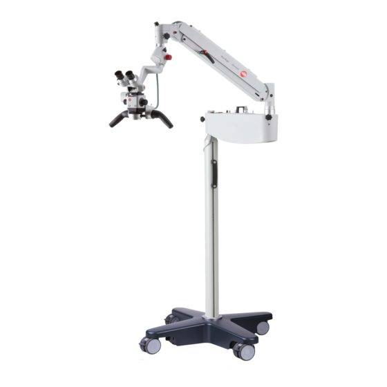
Directive 93/42/EEC 5 Delivery state 5.1 Deliverables The product is delivered as described below (depending on device model). 5.1.1 Deliverables for SOM 62 LED The device is delivered as four individual sub-assemblies: Wheeled stand with four rollers Column ... -
Page 10: Deliverables For Som 22 Led
Instructions for use SOM 62/32/22 LED 5.1.3 Deliverables for SOM 22 LED The device is delivered as three individual sub-assemblies: Wall bracket Swivel and floating arms with electrical supply and lighting Microscope head including attachment Operating instructions Fasteners for all components are included. -
Page 11: Installation
Instructions for use SOM 62/32/22 LED 7 Installation The device may only be installed by personnel assigned by the manufacturer, or by the manufacturer itself. Only the fixing and installation materials supplied may be used. 7.1 Installation of SOM62 7.1.1 Installation of wheeled stand and column Carry out the following installation steps as in Figure 1: ... -
Page 12: Installation Of Swivel Arm, Suspension Arm And Microscope
Instructions for use SOM 62/32/22 LED 7.1.2 Installation of swivel arm, suspension arm and microscope Carry out the following installation steps as in Figure 2: Undo the lock screw (3) on the upright guide cylinder (1) of the column (2) ... -
Page 13: Installation Of Som
Instructions for use SOM 62/32/22 LED 7.2 Installation of SOM 32 7.2.1 Installation of the ceiling bracket Carry out the following installation steps as in Figure 3: Using the aligner (1), drill four holes into the ceiling (Ø 10mm, hole depth 80mm) ... -
Page 14: Installation Of Swivel Arm, Suspension Arm And Microscope
Instructions for use SOM 62/32/22 LED 7.2.2 Installation of swivel arm, suspension arm and microscope Carry out the following installation steps as in Figure 4: Undo the lock screw (2) on the upright guide cylinder (4) of the column (6) ... -
Page 15: Connecting Up To The Voltage Supply
Instructions for use SOM 62/32/22 LED 7.2.3 Connecting up to the voltage supply Plug the connector (1) into the socket (5), noting the orientation of the connector Tighten the sleeve ring (2) Ensure that the spiral cable (4) does not turn excessively when the swivel arm (3) is rotated Figure 5 SOM 62/32/22 LED EN 2017-03... -
Page 16: Installation Of Som
Instructions for use SOM 62/32/22 LED 7.3 Installation of SOM 22 7.3.1 Fitting of the wall bracket Carry out the following installation steps as in Figure 6: Use the drill template (1) to drill four holes into the relevant wall. The lower edge of the drill template must be about 1.65m above the floor. -
Page 17: Installation Of Swivel Arm, Suspension Arm And Microscope
Instructions for use SOM 62/32/22 LED 7.3.2 Installation of swivel arm, suspension arm and microscope Proceed with the steps in Section 7.1.2 8 Device description 8.1 Identification and nameplates The nameplate is used for accurate identification of your product. It may not be removed or modified. -
Page 18: Controls
Instructions for use SOM 62/32/22 LED 8.2 Controls 8.2.1 Controls The device (SOM 62 only) is positioned on the floor with the wheeled stand. The foot has four rollers for moving the device. The following locking mechanisms, securing elements and controls are also fitted on the device (the same applies for SOM 22/32). -
Page 19: Medical Performance Data
Instructions for use SOM 62/32/22 LED 8.3 Medical performance data The medical performance data pertains to the required medical performance data of the medical device. This performance data is listed in Section 16 "Technical description". 8.4 Additional loads The load capacity and tipping stability of the systems are aligned to the components in our product range. -
Page 20: Preparation
Instructions for use SOM 62/32/22 LED 9 Preparation 9.1 Power supply Use the power lead to connect the device to the local voltage supply. 9.2 Brakes The clamps are adjusted by tightening/loosening the star-knob screws (see Section 8.2). The device clamps must be adjusted so that the degree of free movement satisfies the respective requirements. -
Page 21: Focusing
Instructions for use SOM 62/32/22 LED Focusing For dioptre adjustment, first undo the clamping screw (4) on the eyepieces (6). Then line up the "Zero" on the dioptre scale (8) of the eyepieces (6) with the index mark (7) and move the microscope towards the object until it appears in focus. -
Page 22: Operation
Instructions for use SOM 62/32/22 LED 10 Operation 10.1 Transport position / rest position (SOM62 LED only) The device must be moved into a transport position for safe transportation. For this, the clamps of the axes must be undone and the device moved into the transport position shown in Figure 13. The device is at risk of tipping over if not moved WARNING into the transport position described. -
Page 23: Replacing Objective And Eyepieces
Instructions for use SOM 62/32/22 LED 10.2 Replacing objective and eyepieces The following steps are required to replace lenses and eyepieces (refer to Figure 14): The objective (1) has a screwed socket. Turn to the left to release the objective and to the right to affix it. -
Page 24: Switching The Device On And Off
Instructions for use SOM 62/32/22 LED 10.3 Switching the device on and off The main switch (1) of the device is located on the flat side of the swivel arm. The device is ready to use when the green status light (2) is ON. The red status light indicates overheating of the electronics. -
Page 25: Brightness Control
Instructions for use SOM 62/32/22 LED 10.4 Brightness control Turning the potentiometer (1) enables continuously variable adjustment of the LED brightness to the requirements of the user. Figure 16 SOM 62/32/22 LED EN 2017-03... -
Page 26: Magnification Adjustment
Instructions for use SOM 62/32/22 LED 10.5 Magnification adjustment 10.5.1 Magnification setting on the changer Magnification is used to make the finest of structures visible. 3-level (0.63, 1, 1.6) or 5-level (0.4, 0.63, 1, 1.6, 2.5) magnification can be selected depending on model. Turn the knob (1) to set the magnification required. -
Page 27: Swivelling In/Out The Filter
Instructions for use SOM 62/32/22 LED 10.6 Swivelling in/out the filter The device can be fitted with a colour filter as an option. Move the lever (1) to swivel in the colour filter. Figure 19 10.7 Removing/exchanging the binocular tube ... -
Page 28: Shutting The System Down
Instructions for use SOM 62/32/22 LED 11 Shutting the system down After every treatment, the device must be cleaned and disinfected depending on application and in accordance with the specifications in 12 Cleaning and maintenance. The device must then be moved into the transport position described in 10.1 Transport position / idle position. -
Page 29: Disinfection And Sterilisation
Instructions for use SOM 62/32/22 LED 12.2 Disinfection and sterilisation Moisten a cloth with antiseptic liquid (such as Sagrotan – P). Wipe as required the parts of the microscope touched most often (such as knobs and hand grips). For some controls, sterilizable covers are available. We recommend replacing these after 30 sterilization cycles with new ones. -
Page 30: Accessories
Instructions for use SOM 62/32/22 LED country. 14 Accessories The system is a medical product and has been developed and tested in accordance with applicable standards. Do not use any accessory parts that are not approved for the device or do not satisfy the applicable standards/directives. -
Page 31: When Faults Occur
Instructions for use SOM 62/32/22 LED 15 When faults occur The device works extremely reliably when used as intended. Should faults occur nevertheless, please follow the instructions in Section 15.1. 15.1 Summary of potential faults Fault Cause Fault Rectification No microscope lighting Mains switch in OFF position Move the switch to "ON"... -
Page 32: Technical Description
EN ISO 14971:2009-10 EN ISO 13485:2010-01 DIN EN 980: 2008-08 ISO 11884-1-2006 EN ISO 9001:2008 DIN EN 62471:2009-03 Directive 93/42/EEC Manufacturer Karl Kaps GmbH & Co. KG / Asslar CE mark SOM 62/32/22 LED EN 2017-03... -
Page 33: Dimensions
Instructions for use SOM 62/32/22 LED 16.2 Dimensions 16.2.1 SOM 62 LED Figure 22 SOM 62/32/22 LED EN 2017-03... -
Page 34: Som 32 Led
Instructions for use SOM 62/32/22 LED 16.2.2 SOM 32 LED Figure 23 16.2.3 SOM 22 LED Figure 24 SOM 62/32/22 LED EN 2017-03... -
Page 35: Declaration Of Conformity
LED-Beleuchtung Operation-/ Diagnostic-microscope with LED-illumination Typen/types: SOM 62 LED; SOM 32 LED; SOM22 LED Klasse/class: Wir erklären hiermit, dass das hier beschriebene Medizinprodukt mit den Forderungen der Richtlinie 93/42/EWG, Anhang I übereinstimmt. Der Nachweis hierzu wurde mit dem Konformitätsbewertungsverfahren nach Anhang VII geführt. -
Page 36: Warranties
All warranty claims must be directed to the organisation that sold you the device. In special cases, please contact: Karl Kaps GmbH & Co. KG Schulstrasse 57 35614 Asslar, Germany...
Need help?
Do you have a question about the SOM 62 LED and is the answer not in the manual?
Questions and answers