
Related Manuals for Genesys IDU-450 8.0H


Summary of Contents for Genesys IDU-450 8.0H
- Page 1 IDU-450 EFIS Software Version 8.0H (Rotorcraft) IDU-450 8.0H (Rotorcraft) Pilot Guide PRECISE PERFORMANCE. P R O V E N E X P E R I E N C E . PERSONALIZED ATTENTION.
- Page 2 No part of this document may be reproduced in any form, or by any means, without prior written consent of Genesys Aerosystems. FlightLogic and Virtual VFR are trademarks of Genesys Aerosystems. All other brand names and trademarks are the property of their respective holders.
- Page 3 Revision Record Notes/Pages changed, added, or Date Author deleted by current revision Nov 2018 G. Schmidt Rev A Apr 2019 G. Schmidt Fixed footer in Section 5 to read “8.0H” instead of “8.0F.” Title page: Changed copyright to 2019 and changed footer to reflect Rev A Apr 2019.
-
Page 4: Table Of Contents
IDU-450 EFIS Software Version 8.0H Table of Contents Section 1 Introduction ................. 1-1 1.1. Introduction ................1-1 1.2. EFIS/FMS Description ............1-1 1.3. About This Guide ..............1-2 Section 2 System Overview ..............2-1 ... - Page 5 IDU-450 EFIS Software Version 8.0H 3.1.1. PFD (PFI) Symbology ..........3-1 3.1.2. Basic Mode ..............3-2 3.2. Menu Functions ..............3-2 3.2.1. Altitude Display and Altimeter Setting ......3-3 3.2.2. Selected Altitude Sub-Mode (Target Altitude) .... 3-4 ...
- Page 6 IDU-450 EFIS Software Version 8.0H 3.3.25. No Autopilot or Fully-Integrated Autopilot Course Deviation Indicator ................. 3-31 3.3.26. Vertical Deviation Indicator ........3-31 3.3.27. Vertical Deviation Indicator (EFIS Coupled) ..... 3-33 3.3.28. Highway in the Sky/Skyway ........3-34 ...
- Page 7 IDU-450 EFIS Software Version 8.0H 3.5.4. Air Data and Groundspeed ........3-60 3.5.5. Clock ................. 3-60 3.5.6. Fuel Totalizer/Waypoint Distance Functions .... 3-61 3.6. Navigation Log ..............3-61 3.6.1. Clock and Groundspeed ........... 3-61 ...
- Page 8 IDU-450 EFIS Software Version 8.0H 4.4.1. MFD Failure Mode 1 ..........4-10 4.5. PFD Failure Mode 2 (Normal Mode) ........4-11 4.5.1. MFD Failure Mode 2 ..........4-11 4.6. PFD Failure Mode 3 .............. 4-12 ...
- Page 9 IDU-450 EFIS Software Version 8.0H 5.7.6. Flight Plan (FPL) Menu Create-Edit (MFD Only) (Step- By-Step) .................. 5-13 5.7.7. Activate Flight Plan (MFD Only) (Step-By-Step) ..5-14 5.7.8. Edit Flight Plan (MFD Only) (Step-By-Step) ..... 5-15 ...
- Page 10 IDU-450 EFIS Software Version 8.0H 5.16. PFD Source (SOURCE) Menu ..........5-39 5.16.1. PFD Page First-Level Source Selection (Step-By- Step) .................. 5-40 5.17. PFD Bugs (BUGS) Menu ............5-41 5.17.1. PFD Bugs (BUGS) Menu (Step-By-Step) ....5-43 ...
- Page 11 IDU-450 EFIS Software Version 8.0H 7.5.2. EFIS True North Mode ..........7-23 7.6. GPS Altitude ................. 7-23 7.7. Dead Reckoning ..............7-23 7.8. Geodesic Path Computation Accuracy ......... 7-23 7.9. Parallel Offsets ..............7-23 ...
- Page 12 IDU-450 EFIS Software Version 8.0H 8.2. Terrain Display ................ 8-2 8.3. Forward Looking Terrain Alert (FLTA) Function ..... 8-2 8.3.1. FLTA Modes ..............8-3 8.3.2. GPS/SBAS Navigation Mode Slaving ......8-3 8.3.3. Default FLTA Mode .............
- Page 13 IDU-450 EFIS Software Version 8.0H 9.13. Jeppesen NavData Chart Compatibility ........9-6 9.14. ARINC-424 Path-Terminator Leg Types ........ 9-6 9.15. Data Logging and Retrieval ............ 9-6 9.15.1. Delete Log Files ............9-7 9.15.2.
- Page 14 IDU-450 EFIS Software Version 8.0H S 2.2. Strikes Page Screen Range ........S-2 S 2.3. Air Data and Groundspeed ......... S-2 S 2.4. Clock and Options ............S-3 S 2.5. Active Flight Plan Path/Manual Course/Runways ..S-3 ...
- Page 15 IDU-450 EFIS Software Version 8.0H RD 6. Heading Display ............... RD-6 RD 7. Turn Rate Indicator ............RD-7 RD 8. RED-X (Invalid Input) ............RD-7 SAR 1. Search and Rescue (SAR) Patterns ......SAR-1 ...
- Page 16 IDU-450 EFIS Software Version 8.0H List of Figures and Tables 1-1: IDU-450 I ..........1-2 IGURE NPUT DENTIFICATION 2-1: IDU-450 P ........2-11 IGURE RIMARY LIGHT ISPLAY 2-2: IDU-450 M ......2-12 IGURE ULTIFUNCTION LIGHT ISPLAY 2-3: S ..............
- Page 17 IDU-450 EFIS Software Version 8.0H 3-16: VSI ..................3-8 IGURE 3-1: S ......... 3-8 ABLE CALE RADUATIONS AND ISPLAY 3-17: VSI B ................3-9 IGURE 3-18: VSI B ) ........3-9 IGURE ERTICALLY NTEGRATED 3-19: N AGL I ............
- Page 18 IDU-450 EFIS Software Version 8.0H 3-52: H ..............3-30 IGURE EADING 3-53: LNAV A ............3-30 IGURE RMED 3-54: CDI N ..3-31 IGURE UTOPILOT OR ULLY NTEGRATED UTOPILOT 3-55: V ........3-31 IGURE ERTICAL EVIATION NDICATOR 3-11: V ......
- Page 19 IDU-450 EFIS Software Version 8.0H 3-87: L ............3-53 IGURE OSS OF AVIGATION 3-88: F ..............3-54 IGURE IELD OF 3-89: R ................3-54 IGURE ANGE 3-90: HSI P ................. 3-55 IGURE 3-91: HSI P ............3-56 ...
- Page 20 IDU-450 EFIS Software Version 8.0H 4-11: PFD F 3 AHRS F ; GPS/SBAS IGURE AILURE AILED ..................4-12 ORMAL 4-12: MFD F 3 AHRS F ; GPS/SBAS IGURE AILURE AILED ..................4-12 ORMAL 4-13: PFD F 4 GPS/SBAS ADC F ;...
- Page 21 IDU-450 EFIS Software Version 8.0H 5-22: MFD F ..........5-49 IGURE AULT ISPLAY 5-23: MFD F ......5-51 IGURE OTALIZER UANTITY 5-24: MFD P (PAGE) M ..........5-51 IGURE 5-25: MFD HSI D (DCLTR) M ......5-53 ...
- Page 22 IDU-450 EFIS Software Version 8.0H 8-1: T ..............8-2 IGURE ERRAIN ISPLAY 8-2: FLTA INHBT ................ 8-2 IGURE 8-3: D FLTA INHBT ............8-4 IGURE EFAULT 8-4: FLTA INHBT M ........... 8-4 IGURE REAS 8-2: FLTA S HTAWS ........
- Page 23 IDU-450 EFIS Software Version 8.0H T-4: P PA T ..T-3 ABLE ILOT ELECTED RAFFIC LTITUDE ILTERING T-4: T .............. T-4 IGURE RAFFIC HUMBNAIL T-5: T ............. T-4 IGURE RAFFIC ISPLAY ORMAT T-6: T ....T-5 IGURE RAFFIC CREEN...
- Page 24 IDU-450 EFIS Software Version 8.0H RD-6: A ............RD-3 IGURE LTITUDE ISPLAY RD-7: A ) ....RD-4 IGURE LTITUDE ISPLAY ELOW EVEL RD-8: A ADC ....RD-4 IGURE IRSPEED AND LTITUDE WITH OSS OF RD-9: T ............ RD-4 ...
-
Page 25: Introduction
The Genesys Aerosystems EFIS goal is IFR-VFR equivalence with HUD symbology overlaying real-time 3-D virtual view of the outside world. This “synthetic vision” provides the pilot in IMC with simple visual clues for navigation and aircraft control as those used in VFR conditions. -
Page 26: About This Guide
1.3. About This Guide Operation of the Genesys Aerosystems EFIS is described in detail and divided into sections as follows: TABLE OF CONTENTS: Locate areas by topic INTRODUCTION (Section 1): Basic explanation of the pilot guide. - Page 27 Section 1 Introduction conditions; coloring conventions; abbreviations and acronyms; and database update procedures. DISPLAY SYMBOLOGY (Section 3): Identification of each screen element of the PFD/MFD, and explanation of symbology. REVERSIONARY MODES (Section 4): Views of displays with various sensor failed conditions and resulting symbology, as well as, examples of various configurations and display formats used with specific tables showing affected functions.
- Page 28 Section 1 Introduction INDEX: Alphabetical listing of terms or keywords with corresponding page numbers. GLOSSARY: Alphabetical listing of definitions for terms. IDU-450 EFIS Software Version 8.0H (Rotorcraft) Ed Nov 2018...
-
Page 29: System Overview
Section 2 System Overview Section 2 System Overview Abbreviations and Acronyms No Radius Three-Dimensional Advisory Circular ACTV Active ADAHRS Air Data Attitude Heading Reference System Air Data Computer Automatic Direction Finder ADS-B Automatic Dependent Surveillance-Broadcast AFCS Automatic Flight Control System Aircraft Flight Manual Above Ground Level AHRS... - Page 30 Section 2 System Overview Baro Barometric setting Baro-VNAV Barometric Vertical Navigation Backcourse navigation Brightness Bottom Celsius Course to Altitude (ARINC-424 Leg) CALC as in RAIM (R2) Crew Alerting System Course to DME Distance (ARINC-424 Leg) Counter Clockwise Continuous Descent Approach Course Deviation Indicator Course to Fix (ARINC-424 Leg) Course to Intercept (ARINC-424 Leg)
- Page 31 Section 2 System Overview Direct to Fix (ARINC-424 Leg) DFCS Digital Flight Control System DFLT Default Directional Gyro Decision Height DLNK Datalink Distance Measuring Equipment RTCA Document Department of Defense Departure Procedure Dead Reckoning EFIS Electronic Flight Instrument System Earth Gravity Model EGNOS European Geostationary Navigation Overlay Service EGPWS...
- Page 32 Section 2 System Overview Flight Information Service FIS-B Flight Information Service-Broadcast Flight Level FLTA Forward Looking Terrain Awareness Course from Fix to Manual termination (ARINC-424 Leg) Flight Management System Field of View Flight Plan Feet per minute Flight Path Marker FPNM Feet Per Nautical Mile Fixed-Radius Transition...
- Page 33 Section 2 System Overview Holding, Pattern to Fix (ARINC-424 Leg) Altitude or Manual Termination (ARINC-424 Leg) Horizontal Alert Limit Height Above Threshold Heading HFOM Horizontal Figure of Merit hh:mm:ss Hours: Minutes: Seconds HITS Highway in the Sky HLTH Health HORIZ Horizontal HOTAS Hands on Throttle and Stick...
- Page 34 Section 2 System Overview IVSI Instantaneous Vertical Speed Indicator Intermediate Approach Waypoint Kilo=1000 Kilobyte Kilohertz KIAS Knots Indicated Airspeed Knot - Nautical Mile per Hour KTAS Knots True Airspeed Latitude Liquid Crystal Display Local Localizer-type Directional Aid Light Emitting Diode LGND Legend LIFR...
- Page 35 Section 2 System Overview MESO Mesocyclonic METAR Routine hourly weather report Multifunction Display Minimum Middle Marker Military Operations Area Mark On Target MSAS Japan’s MTSAT-based Satellite Augmentation System Message Mean Sea Level MVFR Marginal Visual Flight Rules U.S. National Airspace System Navigation NAVAID Device or system providing navigational assistance...
- Page 36 Section 2 System Overview Procedure Turn (ARINC-424 Leg) Pitch Limit Indicator Pilot Personality Module Part Number; Pan PROC Procedure Pseudo-Random-Noise (Satellite communications) Press Previous Push Parallel offset (Parallel Track) PTRS Pointers Power Altimeter setting provides height above reference point Altimeter setting provides pressure altitude readout Altimeter setting provides MSL altitude at a reporting point Resolution Advisory (Traffic Function) RADALT...
- Page 37 Section 2 System Overview Search and Rescue Saturation SATLT Satellite SBAS Satellite-Based Augmentation System System Configuration Card (personality module) SECAM Analog color television system used in France Side-in-Command Standard Instrument Departure SIGMET Significant Meteorological Advisory Sign Status Matrix STAB Stability STAR Standard Terminal Arrival Routes STBY...
- Page 38 Section 2 System Overview TIS-B Traffic information Service-Broadcast Tilt TRANS Transition Track TRNDO Tornadic Technical Standard Order Time to Alert TURB Turbulence Universal Serial Bus, data storage device User Waypoint Universal Time Coordinated Heading to Altitude (ARINC-424 Leg) Speed above which it is unwise to make full application of any single flight control Vertical Alert Limit Target approach airspeed...
-
Page 39: System Overview
Section 2 System Overview Vertical Protection Level Procedure Speed PROC Rotation speed Heading to Radial Termination (ARINC-424 Leg) Landing reference speed or threshold crossing speed Vertical Speed Vertical Speed Indicator Vectors to Final Minimum speed for a positive rate of climb with one engine inoperative WAAS Wide Area Augmentation System... -
Page 40: Functional Integration And Display Redundancy
Section 2 System Overview At any given time, each system only has one IDU transmit enabled to send RS-232 and RS-422 system transmissions. By default, the PFD is transmit enabled and, if it subsequently fails, the respective MFD becomes transmit enabled. -
Page 41: Idu Initialization
Upon power-up, the hardware, including file system, IO, and graphics, is initialized. Immediately after graphics initialization, a logo screen with “INITIALIZING” is displayed with the Genesys Aerosystems logo, software version number, and part number. Software version number delineates: (1) major revision number (i.e., “8.0”), and (2) minor revision letter (i.e., “H”). - Page 42 Section 2 System Overview Aircraft configurations are initially read from flash drive storage to provide IDUs with a default configuration setup in the event of personality module failure. The personality module contains the CPU number (Table 2-2) and system designation (pilot or co-pilot). The CPU number is identified below the part number on the initialization screen (Figure 2-4).
- Page 43 Section 2 System Overview VOR/LOC 2 OBS setting is set to 360°. Parallel offset is set to 0 NM. PFD zoom mode is set to off. Manual RNP is set to off. PFD skyway is set to on. Airspeed bug is turned off. Target and preselected altitude bugs are turned off True North mode is turned off.
- Page 44 Section 2 System Overview During this action, “PRESS ANY BUTTON TO QUICK START” is displayed below “TESTING.” Press any button to stop the ground booting and execute the flight booting. If the BIT (built-in-test) check fails, the program exits with an error message and creates a BIT result file indicating failure.
- Page 45 Section 2 System Overview Figure 2-7: Two-Minute Countdown Screen The display screens initialize at the earliest of: a) when 2 minutes have elapsed; b) when the pilot presses any button to escape the startup countdown; or c) when all critical sensors are in normal condition. Display screens initialize as follows: a) IDU #1: PFD screen b) Other IDUs: IDU #2 initializes to MFD screen.
-
Page 46: General Arrangement
Section 2 System Overview Figure 2-8: QUICK START Screen 2) BIT result file created during the last ground boot is checked. a) Failure = indicates a failure, program exits with an error message. b) Passage = program continues. 3) The display screens initialize immediately as follows: a) IDU #1: PFD Screen b) Other IDUs: IDU #2 initializes to MFD screen. -
Page 47: Data Source Monitors
Section 2 System Overview 3) Serial protocol converters 4) Video format converters Data storage is sufficiently sized to hold world terrain, navigation, and obstruction databases. Because the receive ports are connected to the digital sensor modules in parallel, each IDU is independent from all others. 2.3.1 Data Source Monitors IDUs continuously monitor the ADC, AHRS, and GPS sensors to detect... -
Page 48: Color Conventions
55 KIAS and transition to flight above 55 KIAS as soon as practicable. NOTE: Not applicable for rotorcraft with other AHRS than Genesys ADAHRS installed. Color Conventions The EFIS uses a consistent set of colors to display information. Any color representation may not be identical as it appears on the IDU. -
Page 49: Warning/Caution/Advisory System
Section 2 System Overview GRAY as background for airspeed and altitude readout and for conformal runway depiction (light gray for usable portion of active runway, dark gray for other runway surfaces). GREEN (light green for visibility) for VOR #2 and to indicate normal or valid operation (airspeed, altitude tape coloring, status indication, engine, etc.). -
Page 50: Time-Critical Warning And Caution Alerts
Section 2 System Overview 1) Warning Alerts 2) Time-Critical Warning Alerts 3) Master Visual and Audible Alerts 4) Caution Alerts 5) Advisory Alerts All warnings, including time-critical warnings, activate the warning (red) light and master caution light. All cautions, including time-critical cautions, activate the caution (yellow) light and master caution light. - Page 51 Section 2 System Overview Figure 2-10: Time-Critical Caution Alert Table 2-3: Time-Critical Warning and Caution Alerts in Primary Field of View Alert Type Text Color Flash Rate Audio Alert at Full Volume Repeated until 2 Hz acknowledged Amber 1 Hz Plays only once (Yellow) Table 2-4: Time-Critical Warning and Caution Alerts...
- Page 52 Section 2 System Overview Table 2-4: Time-Critical Warning and Caution Alerts Voice Alert Condition Visual Alert “--” No Voice Alert ** No time delay Within GPWS Mode 1 warning “Pull Up, envelope. Pull Up” Half-second time delay. Within GPWS Mode 2 warning “Terrain, Terrain, envelope.
-
Page 53: Warning Alerts
Section 2 System Overview Table 2-4: Time-Critical Warning and Caution Alerts Voice Alert Condition Visual Alert “--” No Voice Alert ** No time delay Annunciates horizon synchronization function is engaged. Annunciation does not flash nor illuminate a master visual alert, because it is not really a caution but instead is a pilot selection annunciation. - Page 54 Section 2 System Overview Table 2-5: Warning Alert Elements Flash Audio Alert Type Alert Location Rate at Full Volume PFD lower left corner of Repeated until 2 Hz transmit acknowledged enabled IDU Table 2-6: Warning Alerts Visual Alert Voice Alert Condition ** No time delay One of the following conditions is true:...
-
Page 55: Caution Alerts
Section 2 System Overview Table 2-6: Warning Alerts Visual Alert Voice Alert Condition ** No time delay Resolution advisory. Not given if own aircraft at or below 400’ AGL. Not given if target is at or below “Traffic, Traffic” 200’ AGL (ground target). Audio not generated with TCAS-II system. - Page 56 Section 2 System Overview Table 2-8: Caution Alerts Voice Alert/ Visual Alert Condition Alert Tone ** No time delay Only active in dual-sensor installation with neither sensor in failure condition Only active in dual-system (pilot and co-pilot) Only active when single-pilot mode discrete not asserted Enabled by ADS-B out fail warning limits setting.
- Page 57 Section 2 System Overview Table 2-8: Caution Alerts Voice Alert/ Visual Alert Condition Alert Tone ** No time delay Only active in dual-sensor installation with neither sensor in failure condition Only active in dual-system (pilot and co-pilot) Only active when single-pilot mode discrete not asserted Only when fresh intra-system monitor messages are received.
- Page 58 Section 2 System Overview Table 2-8: Caution Alerts Voice Alert/ Visual Alert Condition Alert Tone ** No time delay Only active in dual-sensor installation with neither sensor in failure condition Only active in dual-system (pilot and co-pilot) Only active when single-pilot mode discrete not asserted Based upon flight plan in use on the indicated side, less than 30 minutes buffer (at current groundspeed)
- Page 59 Section 2 System Overview Table 2-8: Caution Alerts Voice Alert/ Visual Alert Condition Alert Tone ** No time delay Only active in dual-sensor installation with neither sensor in failure condition Only active in dual-system (pilot and co-pilot) Only active when single-pilot mode discrete not asserted Compares the volume of fuel designated left wing tank fuel vs.
- Page 60 Section 2 System Overview Table 2-8: Caution Alerts Voice Alert/ Visual Alert Condition Alert Tone ** No time delay Only active in dual-sensor installation with neither sensor in failure condition Only active in dual-system (pilot and co-pilot) Only active when single-pilot mode discrete not asserted Track: If groundspeed is greater than 30 kts, miscompare if difference is more than 4°.
- Page 61 Section 2 System Overview Table 2-8: Caution Alerts Voice Alert/ Visual Alert Condition Alert Tone ** No time delay Only active in dual-sensor installation with neither sensor in failure condition Only active in dual-system (pilot and co-pilot) Only active when single-pilot mode discrete not asserted Indicates that radar altitude difference between radar altimeters is beyond limits.
- Page 62 Section 2 System Overview Table 2-8: Caution Alerts Voice Alert/ Visual Alert Condition Alert Tone ** No time delay Only active in dual-sensor installation with neither sensor in failure condition Only active in dual-system (pilot and co-pilot) Only active when single-pilot mode discrete not asserted TAWS autorotation mode activated Alert Tone through use of discrete input.
-
Page 63: Side-Specific Caution Alerts
Section 2 System Overview Table 2-8: Caution Alerts Voice Alert/ Visual Alert Condition Alert Tone ** No time delay Only active in dual-sensor installation with neither sensor in failure condition Only active in dual-system (pilot and co-pilot) Only active when single-pilot mode discrete not asserted Within GPWS Mode 1 caution “Sink Rate, envelope. -
Page 64: Advisory Alerts
Section 2 System Overview 2.5.5 Advisory Alerts Figure 2-13: Advisory Alerts Table 2-10: Advisory Alert Elements Type Alert Location Appearance Audio Alert PFD lower left Single advisory corner of While condition chime played transmit persists at 80% volume enabled IDU Table 2-11: Advisory Alerts Visual Alert Alert Tone... -
Page 65: Side-Specific Advisory Alerts
Section 2 System Overview Table 2-11: Advisory Alerts Visual Alert Alert Tone Condition ** No time delay Only active in dual-sensor installation with neither sensor in failure condition Only active in dual-system (pilot and co-pilot) Only active when single-pilot mode discrete not asserted Indicates mismatch of altimeter Chime settings or altimeter modes between... - Page 66 Section 2 System Overview These type of alerts are used where the pilot and copilot systems can generate different alerts, such as when the pilot and co-pilot systems are not crossfilled and are operating on different FMS flight plans. Table 2-12: Side-Specific Advisory Alerts Visual Alert Alert Tone Condition ** No time delay...
- Page 67 Section 2 System Overview Table 2-12: Side-Specific Advisory Alerts Visual Alert Alert Tone Condition ** No time delay Automatic waypoint sequencing is suspended under any of the following conditions: 1) Pilot has selected a manual GPS/SBAS OBS. 2) Active waypoint is the missed approach waypoint, and missed approach procedure has not been armed (ARM) nor initiated (MISS).
-
Page 68: Audio-Only Caution And Advisory Alerts
Section 2 System Overview 2.5.7 Audio-Only Caution and Advisory Alerts Table 2-13: Audio-Only Caution and Advisory Alerts Caution or Voice Alert/ Condition Advisory Alert Alert Tone ** No time delay Deviation from above to below Minimum Altitude “Minimums, minimum altitude bug. Minimum Caution Alert Minimums”... -
Page 69: Voice Alerts And Muting
Section 2 System Overview Table 2-13: Audio-Only Caution and Advisory Alerts Caution or Voice Alert/ Condition Advisory Alert Alert Tone ** No time delay Loss of vertical navigation caution. Inhibited during and Loss of Vertical for 10 seconds after unusual Navigation Alert Tone attitude mode. -
Page 70: Database And Software Updates
NOTE: When ordering, review the EFIS Equipment-Database Compatibility Matrix (document 01-000062) on the Genesys Aerosystems website. This document specifies the compatibility of Genesys Aerosystems EFIS equipment and software versions to navigation database versions. -
Page 71: Update Requirements
Section 2 System Overview 5) RNAV DPs and STARs, including all waypoints, intersections, and associated RNP values (if applicable). DPs and STARs are retrievable as a procedure (select the procedure by name to load the appropriate waypoints and legs into the flight plan). 6) LNAV approach procedures in the area(s) in which IFR operation is intended consist of: a) Runway number and label (required for approach identification);... - Page 72 Section 2 System Overview MAGVAR Database - Every 5 years (updated as described in a Genesys Aerosystems Service Bulletin) CAUTION: Failure to update the EFIS with the correct NavData® causes the IDU to remain in continual reboot mode and does not allow any display page to appear.
-
Page 73: Software And Terrain Database Update
Section 2 System Overview 6) Once both databases have been uploaded, power down the IDU, remove the USB flash drive, and lower the USB door. 7) Once each IDU has been updated, power up the entire EFIS in normal flight mode and verify each IDU successfully updated with the latest database by noting the new navigation database and obstruction database cycle expiration dates before acknowledging the initialization screen (Figure 2-4). -
Page 74: Efis Training Tool
Section 2 System Overview NOTE: When operating in Demonstrator mode, the IDU is isolated from all sensors and other IDUs. Flight plans created on an IDU are stored on that IDU alone. To make the flight plan available on all other displays, the following action must be taken. -
Page 75: Display Symbology
Section 3 Display Symbology Section 3 Display Symbology 3.1. Introduction This section details the symbology on the pilot and co-pilot PFD and MFD. This section only describes the PFD configured with the airspeed scale digital configuration set to tapes with both “pure” and “rolling” digital configurations. -
Page 76: Basic Mode
Section 3 Display Symbology 3.1.2. Basic Mode Rolling Rolling digital digital Figure 3-3: PFD in Basic Mode Pure and Rolling Digital The following are no longer present when Basic mode is displayed: 1) Atmospheric perspective 5) Roll pointer option 2) Terrain rendering 6) Bank scale option 3) Obstructions rendering 7) Airport runways... -
Page 77: Altitude Display And Altimeter Setting
Section 3 Display Symbology Figure 3-5: Menu Functions On the PFD, scroll to activate the heading menu. On MFD pages with an adjustable display (e.g., ND, strikes, traffic, or datalink), scroll CW to increase scale or CCW to decrease scale. Selection lists too long to be presented in the available space indicate the location within the list. -
Page 78: Selected Altitude Sub-Mode (Target Altitude)
Section 3 Display Symbology Press BARO (R2) to enter altimeter setting mode and view the altimeter setting in inches of mercury (inHg) or millibars (mbar) value in the lower right corner. Scroll CW to increase or CCW to decrease the QNH. Push ... -
Page 79: Vnav Sub-Mode
Section 3 Display Symbology When in altitude hold mode, the target altitude bug setting annunciation is green, while the target altitude bug is filled-white. When in a climb or descent mode, the target altitude bug setting annunciation is white, and the target altitude bug is hollow-white. -
Page 80: Altitude Display (Vnav Tile)
Section 3 Display Symbology The VNAV altitude bug is a visual reference or, when vertically integrated with an autopilot either fully or partially integrated through the vertical mode discrete input, as a control parameter for climbs or descents. When vertically integrated with an autopilot: When in altitude hold mode, the VNAV altitude bug setting annunciation is green, and the VNAV altitude bug is filled-magenta. -
Page 81: Altitude Display (Metric Units)
Section 3 Display Symbology 3.2.5. Altitude Display (Metric Units) Pilot-selectable altitude values are in metric units with a resolution of 10 meters as depicted. Figure 3-13: Altitude Display (Metric Units) 3.3. PFD Symbology Figure 3-14: PFD Symbology The PFD combines pitot-static information, heading, attitude, 3-D navigation data, and more overlaid on a virtual background of the outside world. -
Page 82: Vertical Speed Indicator
Section 3 Display Symbology Figure 3-15: Minimum Altitude 3.3.2. Vertical Speed Indicator Figure 3-16: VSI The vertical speed indicator (VSI) is depicted in a "worm" format providing analog and digital representation of VSI in feet per minute (fpm). For example, rate of descent in Figure 3-16 is 700 fpm. Table 3-1: Scale Graduations and Display Traffic Installed Scale Limit... -
Page 83: Normal Agl Indication
Section 3 Display Symbology The pilot-selectable VSI bug setting (100 fpm resolution) in this example is set to 1000 fpm descent rate. The vertical speed bug is used either as a visual reference or, when vertically integrated with an autopilot (either fully integrated or partially integrated through use of the vertical mode discrete input), as a control parameter for climbs or descents. -
Page 84: Analog Agl Indication
Section 3 Display Symbology AGL altitude is not displayed in either format when it is greater than the radar altimeter maximum valid altitude nor when it is invalid. Additionally, the AGL indication includes the set decision height (see § 3.3.5). Table 3-2: AGL Indication ≥100 Feet Altitude... -
Page 85: Decision Height
Section 3 Display Symbology Table 3-4: Analog AGL Indicator Markings Major Tick Marks Minor Tick Marks 50’ 60’ 70’ 80’ 90’ 100’ 200’ 300’ 400’ 500’ 1000’ 3.3.5. Decision Height Pilot-settable decision height is displayed above the CDI with the abbreviation DH and by a yellow radial on the analog indicator. - Page 86 Section 3 Display Symbology The airspeed box pointer interacts with the airspeed scale and has graduations every five measurement units with labels every 10 measurement units with high numbers at the top. The airspeed scale range has at least 40-75 measurement units. During an ADC failure, a red “X”...
-
Page 87: Heading Display
Section 3 Display Symbology Airspeed bug is parked in the direction of the difference if airspeed off scale. Figure 3-25: Airspeed Scale Bug Table 3-6: Airspeed Bug Setting Annunciation and Bug Colors Vertically Integrated Autopilot Without Without Airspeed White at all Green when in airspeed climb or Bug Setting times... - Page 88 Section 3 Display Symbology Heading Scale Heading Pointer Ground Track Active Waypoint Synthetic Vision Basic Mode Figure 3-27: Heading Display integral slip indicator is provided and may replace the mechanical slip indicator mounted in the bezel. The slip indicator is a rectangle just below the heading pointer that moves left and right to indicate the lateral acceleration sensed by the AHRS in the same manner as the ball in a mechanical slip indicator.
-
Page 89: Pitch Scale
Section 3 Display Symbology When an active waypoint exists, the heading scale includes a magenta, star-shaped waypoint pointer at a point corresponding with the active waypoint. When the waypoint pointer is displaced from aircraft heading beyond the boundaries of the PFD screen, the waypoint pointer is replaced by a magenta, triangular arrow at either the far-right or far-left limit of the heading scale to indicate the shortest (not necessarily the safest) direction of turn to the active waypoint (Figure 3-30). -
Page 90: Turn Rate Indicator
Section 3 Display Symbology The PFD has large aircraft symbol reference marks fixed in the center of the display. Rotation of the background, pitch scale, and background oriented display elements occur relative to the location of the waterline symbol or large aircraft reference marks. Pitch scale has increments every 5°... -
Page 91: Unusual Attitude Mode
Section 3 Display Symbology 3.3.12. Unusual Attitude Mode Unusual attitude mode is enabled when pitch attitude exceeds +30° or -30° or bank angle exceeds 50° and remains engaged until pitch attitude returns to within 5° of the horizon and bank attitude returns to within 10° of the horizon. - Page 92 Section 3 Display Symbology relative elevation of terrain and obstructions with respect to aircraft altitude and performance is observed by reference to the primary flight information pitch ladder and FPM. The background has two pilot-selectable field of view (FOV) modes, wide FOV mode (approximately 70°) and narrow FOV mode (approximately 35°).
- Page 93 Section 3 Display Symbology NOTE: There is a one-degree dead band to prevent grid flicker while flying along one of the boundary latitudes. The grid space switching changes at one degree less latitude when flying towards the Equator than it does when flying toward the Poles.
- Page 94 Section 3 Display Symbology WARNING: DO NOT USE THIS EFIS FOR TERRAIN-FOLLOWING FLIGHT NOT ATTEMPT TO NAVIGATE USING THE TERRAIN DEPICTION ALWAYS ADHERE TO PUBLISHED NAVIGATIONAL INSTRUMENT PROCEDURES AND NAVIGATIONAL CHARTS IN ALL FLIGHT CONDITIONS When terrain and obstruction rendering is deselected or disabled, the PFD background is a conventional blue over brown attitude display presentation without atmospheric perspective.
- Page 95 Section 3 Display Symbology Obstructions within the following ranges are depicted on the PFD in SVS Basic or SVS TAWS modes: 1) Narrow FOV: 17NM 2) Wide FOV: 12NM Obstructions such as towers, antennas, buildings, and other manmade structures are shown on the PFD display as vertical amber (yellow) lines (see Figure 3-38).
-
Page 96: Flight Path Marker (Velocity Vector)
Section 3 Display Symbology 3.3.14. Flight Path Marker (Velocity Vector) Figure 3-39: Flight Path Marker The FPM appears on the background to coincide with the aircraft’s actual flight path as projected on the outside world. The FPM is laterally displaced parallel to the horizon with respect to the center of the display to account for the difference between aircraft track and heading, and is vertically displaced perpendicular to the horizon to account for aircraft climb or... - Page 97 Section 3 Display Symbology Figure 3-41: FPM Absent (Unusual Attitude Mode) Figure 3-42: PFD with FPM Removed The FPM is not shown in basic mode. In unusual attitude mode, it disappears to allow the pilot to concentrate on the large aircraft symbol reference marks for unusual attitude recovery.
-
Page 98: Hover Vector
Section 3 Display Symbology Figure 3-43: PFD with GPS Failure after 1 Minute 3.3.15. Hover Vector The FPM is removed at low speed, <30 knots groundspeed, and is replaced with hover vector symbology. The hover vector indicates direction and groundspeed of drift at low groundspeeds (when lower than 30 kts) consisting of large aircraft symbol reference marks, an inner concentric ring indicating 10 knots groundspeed, an outer concentric ring indicating 20 knots groundspeed, and a vertical and horizontal dashed line passing... -
Page 99: Bank Angle Scale
Section 3 Display Symbology A diamond-shaped acceleration cue is centered on the gray dot to indicate direction and magnitude of horizontal acceleration. Deviation of the dot in a straight up direction (12 o’clock position) indicates forward flight while straight down (6 o’clock position) indicates rearward flight. Deviation of the dot laterally indicates lateral drift in that direction. -
Page 100: Turn Indication
Section 3 Display Symbology 3.3.17. Turn Indication Rate of turn is available as an option in the PFD declutter menu to show a worm in the direction of turn with full-scale deflection indicating a standard rate of turn and half-standard rate indicated at the mid-scale marking. -
Page 101: Course Deviation Indicator (Cdi)
Section 3 Display Symbology FD1 Single Cue FD2 Dual Cue Figure 3-49: Flight Director FD1 Single Cue FD2 Dual Cue Figure 3-50: Flight Director (Basic Mode) 3.3.21. Course Deviation Indicator (CDI) Without Autopilot With Autopilot Figure 3-51: Course Deviation Indicator The order of precedence of type accuracy used by the system from highest to lowest is as follows: Ed Nov 2018... - Page 102 Section 3 Display Symbology 1) Manual RNP: The pilot may override the automatic accuracy types by setting a manual RNP value. 2) Automatic RNP: These are based upon RNP values, which are coded in the navigation database. The EFIS looks at the leg coding on all legs other than those on the final approach segment.
-
Page 103: Obs Setting Of Cdi
Section 3 Display Symbology Table 3-10: CDI Behavior and Color CDI Pointer and Condition Color or Behavior of the first fix in the departure procedure. Slaved to GPS/SBAS (with GPS Amber (Yellow) loss of navigation) Normal conditions Magenta In sources other than FMS Angular scale annunciation Navigation source is localizer Reverse sensing... -
Page 104: Heading/Roll-Steering Sub-Mode
Section 3 Display Symbology 3.3.23. Heading/Roll-Steering Sub-Mode Heading/roll-steering sub-mode annunciation appears immediately right of the selected navigation source annunciation and displays: 1) HDG: LVL (Wing-Leveling Sub-Mode Guidance) 2) HDG: LNAV (LNAV Sub-Mode Guidance) 3) HDG: BUG (Heading Bug Sub-Mode Guidance) 4) HDG: --- (Failure Sub-Mode) 3.3.24. -
Page 105: No Autopilot Or Fully-Integrated Autopilot Course Deviation Indicator
Section 3 Display Symbology 3.3.25. No Autopilot or Fully-Integrated Autopilot Course Deviation Indicator Without Autopilot With HeliSAS-E Figure 3-54: CDI No Autopilot or Fully-Integrated Autopilot In an installation without an autopilot or with a fully integrated autopilot (e.g., HeliSAS-E), the heading/roll-steering sub-mode annunciation is not meaningful and should be decluttered from the CDI display. - Page 106 Section 3 Display Symbology using GPS VNAV. GPS altitude utilized to generate VDI; pilot may follow guidance to LNAV minima regardless of temperature. 3) LNAV Mode and VNV1-B or VNV2-B: Default FMS barometric VNAV mode. Using barometric altitude to generate the VDI, pilot may follow guidance to LNAV minima as long as the specified temperature is within limits.
-
Page 107: Vertical Deviation Indicator (Efis Coupled)
Section 3 Display Symbology Table 3-11: Vertical Deviation Indicator Behavior Source Pointer Behavior/Condition (Below VDI) Color wedge of the azimuth reference point (either the GARP or MAWPT + 10,000 ft.). Pointer and Text Color LPV, VNV-G During GPS LON or GPS VLON Amber (Yellow) Figure 3-56: VDI Color during GPS/SBAS LON or VLON... -
Page 108: Highway In The Sky/Skyway
Section 3 Display Symbology the autopilot is vertically coupled to the selected vertical navigation source. Otherwise, the selected vertical navigation source is white. 3.3.28. Highway in the Sky/Skyway Coupled Uncoupled Figure 3-58: Highway in the Sky When not decluttered, the PFD displays the active navigation route or manual OBS course in 3-D with a series of skyway boxes, which overly the flight plan route at a desired altitude and provide lateral and vertical guidance. -
Page 109: Mini Map
Section 3 Display Symbology 2) a hoop or “tethered balloon” (for fly-over waypoints) or “tethered diamond” (for fly-by waypoints) depicted at the VNAV altitude or at aircraft altitude (if there is no VNAV altitude), and 3) a line connecting the “X” and the hoop. The “X”... -
Page 110: Runways
Section 3 Display Symbology Table 3-12: Mini Map Behavior (When Not Decluttered) Symbology Color Condition VOR 1 When Valid Cyan VOR 2 When Valid Green Magenta GPS/SBAS normal Active Leg Amber (Yellow) GPS/SBAS LON Ownship Symbol (Figure 3-63) White Mutually exclusive with analog AGL, and traffic thumbnail. Mini Map disappears in Unusual Attitude Mode 3.3.31. -
Page 111: Heliports
Section 3 Display Symbology Runways are displayed with hidden surface removal techniques of the terrain and obstruction rendering, so runways behind terrain appear to be so. Runways are based on characteristics in the navigation database, including elevation, position, orientation, length, and width, and displayed as defined in Table 3-13. -
Page 112: Mfd Symbology
Section 3 Display Symbology Figure 3-62: Helipads 3.4. MFD Symbology Navigation display (ND) may be configured the following formats: 1) Moving Map 5) Traffic (see Traffic Appendix) 2) Conventional HSI 6) Datalink (see Datalink 3) Navigation Log Appendix) 4) Strikes (see WX-500 Lightning Strikes Appendix) 3.4.1. -
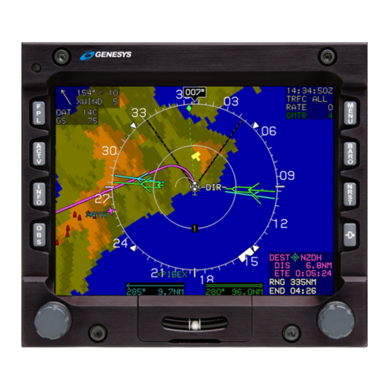
Page 113: Moving Map
Section 3 Display Symbology 3.4.2. Moving Map Figure 3-64: Basic Moving Map NOTE: When selected, latitude/longitude is displayed below the ownship symbol as aircraft current position. Figure 3-65: Latitude/Longitude Display Compass Rose/ND Boundary Circle Symbol Ed Nov 2018 IDU-450 EFIS Software Version 8.0H (Rotorcraft) 3-39... - Page 114 Section 3 Display Symbology Figure 3-66: Moving Map with Instrument Approach Figure 3-67: North-Up Arc Mode 3-40 IDU-450 EFIS Software Version 8.0H (Rotorcraft) Ed Nov 2018...
-
Page 115: Compass Rose/Nd Boundary Circle Symbol
Section 3 Display Symbology Figure 3-68: North-Up Centered Mode Figure 3-69: Heading-Up Centered Mode 3.4.3. Compass Rose/ND Boundary Circle Symbol In heading up mode, the magnetic digital heading readout and pointer are aligned with the longitudinal axis of the ownship symbol. Figure 3-70: Compass Rose/ND Boundary Circle Symbol Ed Nov 2018 IDU-450 EFIS Software Version 8.0H (Rotorcraft) -
Page 116: Clock/Options
Section 3 Display Symbology 3.4.4. Clock/Options The following are displayed in the upper right corner of the ND. Table 3-14: Clock Options Feature Options Notes Zulu Time or hh:mm:ssZ Synchronized with the Local Offset hh:mm:ssL GPS/SBAS constellation. DCLTR A = Automatic declutter mode Declutter Mode DCLTR M = Manual declutter mode... -
Page 117: Fuel Totalizer/Waypoint Distance Functions
Section 3 Display Symbology b) Speed in knots; c) Crosswind component in knots; and d) Graphical wind vector arrow oriented to correspond to the ND orientation. NOTE: Wind information is not shown when the aircraft is in the ground mode, or when the AHRS is in DG mode. -
Page 118: Navigation Data
Section 3 Display Symbology Table 3-15: Fuel Totalizer/Waypoint Distance Functions Type Symbols Function Conditions Options DEST If there is an active flight plan, waypoint ETA or ETE Waypoint type, identifier, range, and ETE/ETA for Degree (°) or the last waypoint (“DEST” waypoint) are True North ( shown. - Page 119 Section 3 Display Symbology Table 3-16: Navigation Symbology IFR Airport VFR Airport High Altitude VORTAC Airway DME only or Low Altitude TACAN Airway User Waypoint User Waypoint HSI CDI scale in Pan Mode The ND has manual and automatic decluttering of navigation data. There are six levels of automatic declutter based upon the number of navigation data symbols drawn in the current ND format and range.
-
Page 120: Analog Navigation Symbology
Section 3 Display Symbology Table 3-17: Airspace Depiction Type of ARINC 424 Airspace Vertical Limits Single pixel dashed lines More than ±500’ Single pixel solid lines Within ±500’ Within airspace Triple pixel solid lines vertical limits Color of Airspace Class C, control area, TRSAs, Class Green Class B, TCAs (where applicable) Blue... -
Page 121: Borders
Section 3 Display Symbology When selected, the ND displays analog (VOR1 and VOR2) navigation symbology, when valid. When the VOR1 and/or VOR2 pointers are selected for display, bearing and distance for the selected VOR pointers appear at the bottom of the ND view (cyan for VOR1; green for VOR2). If the DME channel is in hold mode, the associated distance readout is amber (yellow), and the letter “H”... -
Page 122: Terrain/Obstructions
Section 3 Display Symbology Figure 3-78: Without State Borders Drawn 3.4.10. Terrain/Obstructions Terrain and obstruction rendering is pilot-selectable to declutter the display by deselecting terrain (independent declutter of obstructions is not possible). Furthermore, terrain and obstruction rendering is disabled when: 1) The GPS/SBAS sensor is failed;... - Page 123 Section 3 Display Symbology Figure 3-80: Terrain/Obstructions MFD Terrain is displayed on the ND in its correct relationship to the ownship symbol using color to show relationship to aircraft altitude. Table 3-18: Terrain Color Based on Aircraft Altitude Color Notes Terrain at or below 100 feet Olive shades below aircraft altitude...
-
Page 124: Pan Mode
Section 3 Display Symbology NOTE: See Section 8 Terrain Awareness Warning System for obstructions causing TAWS alarms and depiction of separate symbology. 3.4.11. Pan Mode The ND page has a pan mode for changing the location of the center of the page away from current location and viewing map details along the route of flight and at the intended or alternate destination while either in flight or on the ground. -
Page 125: Direct Point
Section 3 Display Symbology Figure 3-82: Start Point 3.4.13. Direct Point Unnamed waypoints appear depending upon the procedure loaded when a direct-to command is entered. See Section 7 IFR Procedures for more information. -ALT- altitude terminations -DIR- waypoints that begin a Direct -To leg -DME - distance or DME terminations -INT- intercept terminations... -
Page 126: Projected Path
Section 3 Display Symbology lubber line, altitude is captured and shown as a green arc located ahead of the aircraft. The arc marks the bottom-of-descent or top-of-climb point. 3.4.15. Projected Path When the aircraft is in a bank angle, a projected path emanates from the ownship symbol. -
Page 127: Parallel Track
Section 3 Display Symbology procedure are displayed. In addition, the runways associated with the three nearest airports (as computed by the TAWS algorithms) are displayed. 3.4.16.1. Parallel Track When there is an active flight plan and GPS/SBAS OBS setting is automatic, the flight plan path is shown on the ND in correct relationship to the ownship symbol. -
Page 128: Field Of View Indication
Section 3 Display Symbology 3.4.17. Field of View Indication The ND background indicates the ND FOV with a set of segmented gray lines leading out from the ownship symbol in either 35° or 70° angles depending on the zoom mode setting on the PFD. Normal FOV (Zoom Off) Narrow FOV (Zoom On) Figure 3-88: Field of View... -
Page 129: Hsi Page
Section 3 Display Symbology 3.5. HSI Page When selected, the ND displays conventional HSI symbology, including a selected course needle, a lateral deviation indicator, and a TO-FROM indicator. VOR1, VOR2, and ADF navigation are displayed with a magenta single line FMS1 (), a cyan single line VOR1 needle (), and a green double line VOR2 needle (), and ADF () tuned to an NDB. -
Page 130: Conventional Hsi/Ptr Format
Section 3 Display Symbology A VDI appears, as in Figure 3-90, when the VDI source is valid to display vertical deviation information for the currently selected navigation source. When the selected vertical source is FMS, the VDI displayed on the HSI has the same behavior as the VDI displayed on the PFD with the exception of the VDI source displayed on the top of the VDI to avoid clutter with waypoint information below:... -
Page 131: Analog Navigation Symbology
Section 3 Display Symbology groundspeeds greater than 30 kts. When selected, the VLOC1, with GS1 is displayed. When the signal is invalid, the associated pointer is not shown. Figure 3-92: Conventional HSI/PTR Format: HSI with VDI and Glideslope When VOR1 and VOR2 pointers are selected for display, a distance display at the bottom of the ND appear. - Page 132 Section 3 Display Symbology When the signal is invalid, the associated pointer is not shown. When the signal is valid for VOR1 and VOR2, a bearing and distance display for the selected VOR pointers appears at the bottom of the display in the same color of the respective pointer.
-
Page 133: Compass Rose Symbols
Section 3 Display Symbology Figure 3-96: HSI Bearing Distance Readout with DME in HOLD Valid marker beacon discretes are displayed on the PFD and ND HSI with appropriate coloring markings. Only during a built-in-test, more than one marker beacon may be active. Marker beacons are disabled when the NAV source is FMS. -
Page 134: Air Data And Groundspeed
Section 3 Display Symbology pointer on the compass rose. A magenta, star-shaped waypoint pointer is displayed on the heading scale at a point corresponding with the active waypoint but turns amber (yellow) in the event of GPS LON caution. NOTE: See Section 7 IFR Procedures for description of the following heading modes with the AHRS and EFIS: 1) ADAHRS Slaved—EFIS Magnetic North... -
Page 135: Fuel Totalizer/Waypoint Distance Functions
Section 3 Display Symbology 3.5.6. Fuel Totalizer/Waypoint Distance Functions Fuel totalizer and waypoint distance are displayed in the lower right corner of the HSI as specified in § 3.4.6. Figure 3-101: HSI Fuel Totalizer/Waypoint Distance 3.6. Navigation Log With Fuel Enabled Without Fuel Enabled Figure 3-102: Navigation Log 3.6.1. -
Page 136: Vnav And Vnav Offset Column
Section 3 Display Symbology asterisk, is magenta but turns amber (yellow) in the event of a GPS LON caution. Brackets indicate suppressed waypoints. Navigation data symbols are shown with the waypoint identifier to easily distinguish the waypoint type. When a waypoint is part of a procedure or parallel offset, the following legends are drawn on top of the navigation data symbol: 1) FAF = Waypoint is a final approach fix. -
Page 137: Path Column
Section 3 Display Symbology 3.6.5. Path Column LNAV path between waypoints is displayed immediately to the right of the VNAV and VNAV offset column. The following are displayed: 1) Geodetic path between waypoints is displayed with (R4), followed by the initial geodetic course for the leg. 2) Suppressed waypoints (not part of the active flight plan) are shown as dashes. -
Page 138: Distance Column
Section 3 Display Symbology 3.6.6. Distance Column Distance between waypoints is displayed immediately to the right of the path column and is calculated taking into account the associated path as well as parallel offsets. In the case of a discontinuity, distance between waypoints is the direct geodetic distance between the two waypoints. -
Page 139: Hover Page
Section 3 Display Symbology NOTE: Since a suppressed waypoint is not part of the active flight plan, dashes appear in the absence of the following VNAV data associated with a suppressed waypoint: 1) Path data (dashes) 4) ETA data (dashes) 2) Distance data (dashes) 5) Fuel remaining data (dashes) -
Page 140: Compass Rose Symbols
Section 3 Display Symbology intermediate speed scales (the first between the ownship symbol and the range ring, the second between the range ring and the compass rose) are drawn using dashed lines. The speed range for the hover vector indication changes based upon current groundspeed. -
Page 141: Active Flight Plan Path/Manual Course
Section 3 Display Symbology across the earth appears on the compass rose when groundspeed is greater than or equal to 30 knots. A pilot-settable heading bug geometrically interacting with the heading pointer appears on the compass rose. A magenta, star-shaped waypoint pointer is displayed on the heading scale at a point corresponding with the active waypoint, which turns amber (yellow) in the event of GPS LON caution. -
Page 142: Navigation Data
Section 3 Display Symbology Figure 3-107: Hover Vector Active Flight Plan Path/Parallel Course 3.7.5. Navigation Data The hover page displays navigation data in correct relationship to the ownship symbol. Navigation data symbols include airport symbols, VORs, NDBs, fixes, and user waypoints. The user waypoint symbol on the hover page includes an outlining box sized so it cannot be obscured by the ownship symbol. -
Page 143: Air Data And Groundspeed
Section 3 Display Symbology Figure 3-108: Hover Vector Projected Path 3.7.7. Air Data and Groundspeed Displayed as specified in § 3.4.5. 3.7.8. Clock Displayed as specified in § 3.4.4. 3.7.9. AGL Indication Above 2,500’ AGL 2,500’ AGL 500’ AGL 200’ AGL Figure 3-109: Hover Vector AGL Indication AGL altitude is displayed as an analog indication and digital readout on the right side of the hover page, which is driven by whatever AGL altitude... -
Page 144: Decision Height Indication
Section 3 Display Symbology Digital readout of AGL altitude is not displayed when it is greater than the radar altimeter maximum valid altitude nor when it is invalid. The digital readout of AGL altitude is not displayed when its source is barometric and indicated airspeed is in the noise range (less than 20 KIAS) due to rotor wash effects. -
Page 145: Reversionary Modes
Section 4 Reversionary Modes Section 4 Reversionary Modes 4.1. Reversionary Modes The equipment has eight reversionary modes as follows: Mode 0: GPS/SBAS, ADC, and AHRS normal. Mode 1: GPS/SBAS failed; ADC and AHRS normal. Mode 2: ADC failed; GPS/SBAS, and AHRS normal. Mode 3: AHRS failed;... -
Page 146: Reversionary Modes
Section 4 Reversionary Modes Table 4-1: Reversionary Mode Status (PFD) Mode PFD Functions Airspeed Altimeter Altimeter Set Display Bank Scale Runway Waypoint Pointer Heading Scale AGL Ind. Flight Path Marker Hover Vector Ground Track Heading Indicator Horizon Mini-Map Pitch Scale Highway in the Sky Terrain/Obstructions Clock Functions... - Page 147 Section 4 Reversionary Modes Table 4-2: Reversionary Mode Status (ND) Mode ND Functions Aircraft Position Special Use Airspace Waypoint Pointer Active Flight Plan Path Groundspeed Ground Track Heading Indicator Navigation Symbols Outside Air Temp. Projected Path Traffic Terrain/Obstructions Clock Functions Waypoint Brg./Dist.
- Page 148 Section 4 Reversionary Modes Note 1: Presented using inertial dead-reckoning based on last known wind information. If unable to dead reckon (e.g., heading is failed or true airspeed cannot be calculated), function is disabled. Note 2: Only radar altitude presented when available. Note 3: Last known wind is saved during GPS/SBAS failure.
-
Page 149: Oat Sensor Failure Mode
Section 4 Reversionary Modes Note 18: Only DH function (with valid AGL altitude) in this mode. Note 19: Red-X in place of scale. Note 20: VLOC CDI always available if optional VOR symbology enabled. Note 21: Function removed during heading-only failure mode. Note 22: Rotorcraft versions (Part 27 or Part 29 airspeed scale), use full- time large attitude bars and do not show the waterline symbol. -
Page 150: Gps Failure
Fault detects a position failure that cannot be excluded within time- to-alert when integrity is provided by FDE; e) HPL > HAL on the final approach segment: Genesys Aerosystems EFIS does not transition to DR navigation at this stage. A GPS navigation solution is still presented;... - Page 151 Section 4 Reversionary Modes NOTE: At any time, view HFOM on the FAULTS page to see the system-reported accuracy. Figure 4-3: FAULTS Page on MFD 1) DR (Dead Reckoning) a) If a GPS position cannot be calculated, a dead reckoning solution is provided with a timer .
-
Page 152: Pfd And Mfd Failure Mode Examples
Section 4 Reversionary Modes c) The presence of a condition where fault detection detects a position failure that cannot be excluded; d) There are an insufficient number of SBAS HEALTY satellites; e) The horizontal protection level exceeds the alert limit as follows for LNAV/VNAV approaches: Prior to sequencing the FAWP- HAL should be 0.3 NM with no limit on VAL... -
Page 153: Pfd Failure Mode 0
Section 4 Reversionary Modes 4.3. PFD Failure Mode 0 Figure 4-5: PFD Failure Mode 0 GPS, ADC, and AHRS Normal 4.3.1. MFD Failure Mode 0 (Normal Mode) Figure 4-6: MFD Failure Mode 0 (Normal Mode) GPS, ADC, and AHRS Normal Ed Nov 2018 IDU-450 EFIS Software Version 8.0H (Rotorcraft) - Page 154 Section 4 Reversionary Modes 4.4. PFD Failure Mode 1 Figure 4-7: PFD Failure Mode 1 GPS/SBAS Failed; ADC and AHRS Normal 4.4.1. MFD Failure Mode 1 Figure 4-8: MFD Failure Mode 1 GPS/SBAS Failed; ADC and AHRS Normal 4-10 IDU-450 EFIS Software Version 8.0H (Rotorcraft) Ed Nov 2018...
-
Page 155: Mfd Failure Mode 1
Section 4 Reversionary Modes 4.5. PFD Failure Mode 2 (Normal Mode) Figure 4-9: PFD Failure Mode 2 (Normal Mode) ADC Failed; GPS/SBAS and AHRS Normal 4.5.1. MFD Failure Mode 2 Figure 4-10: MFD Failure Mode 2 ADC Failed; GPS/SBAS and AHRS Normal Ed Nov 2018 IDU-450 EFIS Software Version 8.0H (Rotorcraft) 4-11... -
Page 156: Pfd Failure Mode 3
Section 4 Reversionary Modes 4.6. PFD Failure Mode 3 Figure 4-11: PFD Failure Mode 3 AHRS Failed; GPS/SBAS and ADC Normal 4.6.1. MFD Failure Mode 3 Figure 4-12: MFD Failure Mode 3 AHRS Failed; GPS/SBAS and ADC Normal 4-12 IDU-450 EFIS Software Version 8.0H (Rotorcraft) Ed Nov 2018... -
Page 157: Pfd Failure Mode 4
Section 4 Reversionary Modes 4.7. PFD Failure Mode 4 Figure 4-13: PFD Failure Mode 4 GPS/SBAS and ADC Failed; AHRS Normal 4.7.1. MFD Failure Mode 4 Figure 4-14: MFD Failure Mode 4 GPS/SBAS and ADC Failed; AHRS Normal Ed Nov 2018 IDU-450 EFIS Software Version 8.0H (Rotorcraft) 4-13... -
Page 158: Pfd Failure Mode 6
Section 4 Reversionary Modes 4.8. PFD Failure Mode 5 Figure 4-15: PFD Failure Mode 5 GPS/SBAS and AHRS Failed; ADC Normal 4.8.1. MFD Failure Mode 5 Figure 4-16: MFD Failure Mode 5 GPS/SBAS and AHRS Failed; ADC Normal 4-14 IDU-450 EFIS Software Version 8.0H (Rotorcraft) Ed Nov 2018... - Page 159 Section 4 Reversionary Modes 4.9. PFD Failure Mode 6 Figure 4-17: PFD Failure Mode 6 ADC and AHRS Failed; GPS/SBAS Normal 4.9.1. MFD Failure Mode 6 Figure 4-18: MFD Failure Mode 6 ADC and AHRS Failed; GPS/SBAS Normal Ed Nov 2018 IDU-450 EFIS Software Version 8.0H (Rotorcraft) 4-15...
- Page 160 Section 4 Reversionary Modes 4.10. PFD Failure Mode 7 Figure 4-19: PFD Failure Mode 7 GPS/SBAS, ADC, and AHRS Failed 4.10.1. MFD Failure Mode 7 Figure 4-20: MFD Failure Mode 7 GPS/SBAS, ADC, and AHRS Failed 4-16 IDU-450 EFIS Software Version 8.0H (Rotorcraft) Ed Nov 2018...
-
Page 161: Menu Functions And Step-By-Step Procedures
Section 5 Menu Functions and Procedures Section 5 Menu Functions and Step-By-Step Procedures 5.1. Menu Functions Figure 5-1: IDU-450 Input Controls The top-level menu level corresponds to the permanent labeling of the IDU buttons and is active any time no soft menu options appear on the screen. Soft menu function tiles appear next to the appropriate IDU button and the ... -
Page 162: Menu Philosophy
Section 5 Menu Functions and Procedures 5.1.1. Menu Philosophy The menu system and buttons with an action are clearly labeled. The following rules are in the design of the menu system: EXIT (R1): Whenever menu system is beyond the top- level, provides a one-touch escape to the top-level. -
Page 163: Menu Synchronization
Section 5 Menu Functions and Procedures 5.2. Menu Synchronization System settings changed by the menu system are synchronized between multiple IDUs in MFD-MFD mode. All parameters for rotorcraft are included. Each appendix for Datalink, Strikes, RBP, and Traffic contains specific limitations for menu synchronization for that feature. - Page 164 Section 5 Menu Functions and Procedures Table 5-2: Menu Synchronization Menu Parameter Notes the appearance of any pilot's PFD consistent in the case of PFD reversion. The onside characteristic means that individual pilots can still adjust their PFD settings to their preference. Sensor Selections Transition Altitude Barometric Setting Parameters...
-
Page 165: Menu Function Types
Section 5 Menu Functions and Procedures 5.3. Menu Function Types There are two types of menu functions on the IDU-450; top-level menu functions corresponding to the labeled button, and soft menu functions indicated by menu tiles, which appear on screen. Soft menu function tiles appear next to the appropriate IDU button or in the lower right corner when use of the encoder is appropriate. -
Page 166: Top-Level Menu Automatic Pop-Up Function Descriptions
Section 5 Menu Functions and Procedures 9) #1 Encoder ( a) On a PFD, scroll to activate the heading menu. b) On MFD pages with an adjustable display scale (e.g., ND, Strikes, Traffic, Datalink, or Hover,), scroll to change display scale (CW = increase, CCW = decrease). - Page 167 Section 5 Menu Functions and Procedures Table 5-3: Top-Level Menu Automatic Function Descriptions Tile Legend and Action in Order of Precedence 3) When the display is transmit enabled and HRZ SYNC is engaged, HS OFF appears. Press to cancel HRZ SYNC mode.
-
Page 168: First Page (Pfd)
Section 5 Menu Functions and Procedures 5.5. First Page (PFD) On the IDU-450, IDU #1 is fixed to the PFD page, and other IDUs may show the PFD page as a backup function. IDU-450 PFD page first-level options are as follows. Synchronize pilot and co-pilot systems in dual-... - Page 169 Section 5 Menu Functions and Procedures Table 5-4: Crossfill Inhibit/Arm/Sync Function Action to Indication Synchronize Flight Flight Crossfill (Pilot and Co- Result Plans Plan pilot) Pilot Co-pilot synchronized going forward. removed from both sides. removed. Inhibited Enable crossfill Synchro- (proceed to Cond. 2) (Cond.3) nized displayed on both...
-
Page 170: Pfd Screen First Soft Menu Level
Section 5 Menu Functions and Procedures 5) TIME (OBS) (L4): Activates time menu 6) BUGS (BARO) (R2): Activates PFD bug set menu 7) ZOOM ON/ZOOM OFF (NRST) (R3): Toggles between wide FOV mode and narrow FOV mode. ZOOM ON appears when current mode is wide FOV. -
Page 171: Lower-Level Menus (Below First-Level)
Section 5 Menu Functions and Procedures 1) FAULTS (FPL) (L1): Activates fault display menu 2) CLR STRKS (ACTV) (L2): On ND or Strikes page with WX-500 option enabled, CLR STRKS activates strike clear option for the Goodrich/L- 3 WX-500. On Datalink page, WX LGND.. activates datalink weather legend (see Datalink appendix). -
Page 172: Flight Planner Page
Section 5 Menu Functions and Procedures 5.7.1. Flight Planner Page The flight planner is used for following functions on pilot-modifiable elements in the IDU database. 1) Manage stored flight plans (activate, create, edit, delete, and reverse); 2) Manage user waypoints (create, edit, and delete); and 3) Perform RAIM predictions. -
Page 173: Flight Plan (Fpl) Menu Selecting (Step-By-Step)
Section 5 Menu Functions and Procedures Figure 5-7: Creation of Overfly User Waypoint NOTE: A maximum of 998 user waypoints may be created and stored. When an attempt is made to create additional user waypoints, USER WPTS FULL message appears. 5.7.5. -
Page 174: Activate Flight Plan (Mfd Only) (Step-By-Step)
Section 5 Menu Functions and Procedures 5) Either use to create a new waypoint or press NRST APT.. (L2), NRST VOR.. (L3), NRST NDB.. (L4), NRST FIX.. (R2), or NRST USR.. (R3), and make desired selection. Push enter. 6) When finished, press SAVE (R4) to store the new flight plan as one of 100 flight plans in memory. -
Page 175: Edit Flight Plan (Mfd Only) (Step-By-Step)
Section 5 Menu Functions and Procedures 5.7.8. Edit Flight Plan (MFD Only) (Step-By-Step) 1) Press FPL (L1). 2) Scroll to CREATE-EDIT.. and push to enter. 3) Scroll to EDIT FLIGHT PLAN and push to enter. 4) Scroll to desired flight plan and push to enter. -
Page 176: Delete Flight Plan (Mfd Only) (Step-By-Step)
Section 5 Menu Functions and Procedures 5.7.10. Delete Flight Plan (MFD Only) (Step-By-Step) 1) Press FPL (L1). 2) Scroll to CREATE-EDIT.. and push to enter. 3) Scroll to DELETE FLIGHT PLAN and push to enter. 4) Scroll to desired flight plan to be deleted and push to enter. -
Page 177: Create User Waypoint (Lat-Lon) (Mfd Only) (Step-By-Step)
Section 5 Menu Functions and Procedures 6) Scroll to desired runway and push to enter. 7) If this new approach is to replace the initial procedure, push confirm. Use same procedure for changing a STAR , DP , or instrument approach procedure. -
Page 178: Create User Waypoint (Rad-Dst) (Mfd Only) (Step-By-Step)
Section 5 Menu Functions and Procedures If desired, specify the approach bearing to user waypoint in degrees 1°- 360°. “OFF” disables VFR approaches to the user waypoint. NOTE: Pressing EXIT (R1) only exits menu and does not save the new USER WPT. -
Page 179: Edit User Waypoint (Mfd Only) (Step-By-Step)
Section 5 Menu Functions and Procedures 6) Either press SAVE (R3) user waypoint or press (R4) to create RD001 as the Active waypoint and begin navigation guidance. NOTE: Pressing EXIT (R1) only exits menu and does not save the new USER WPT. -
Page 180: Delete User Waypoint (Mfd Only) (Step-By-Step)
Section 5 Menu Functions and Procedures 5) Use to enter alphanumeric characters; follow prompts to edit information. Push to step through all character spaces back up, press BACK (L1) and continue to the end of all character spaces. 6) Either press SAVE (R3) to save user waypoint or press (R4) to... -
Page 181: Raim Prediction
Section 5 Menu Functions and Procedures 1) EDIT the user waypoint as described in § 5.7.14. 2) Open a flight plan that uses the user waypoint. 3) Delete the existing waypoint from the flight plan. 4) Save and exit. 5) Reload the flight plan if it were in use. 5.7.16. - Page 182 Section 5 Menu Functions and Procedures NOTE: The pilot may perform RAIM prediction at a designated waypoint. The screen has various data entry boxes as follows. 1) Designated Waypoint: Prompted to enter an identifier for the designated waypoint. If there is a single result from the search, the pilot is advanced to the UTC time entry box.
-
Page 183: Active Flight Plan (Actv) Menu
Section 5 Menu Functions and Procedures 5.8. Active Flight Plan (ACTV) Menu 5.8.1. Main Menu See Section 7 IFR Procedures for active flight plan description. Waypoint List Does ACTV active flight plan exist? NO ACTV WPT SYNC Activate selected WAYPOINT* waypoint VNAV.. -
Page 184: Active Flight Plan (Actv) Menu Options
Section 5 Menu Functions and Procedures 5.8.2. Active Flight Plan (ACTV) Menu Options SAVE Save active flight plan Delete active flight plan and ACTV OFF place autopilot INSERT.. roll-steering into wing-leveler mode Delete ACTV INFO.. DELETE selected waypoint Information Menu or procedure for the highlighted waypoint... - Page 185 Section 5 Menu Functions and Procedures 3) INFO (L3): Activates information menu option for highlighted waypoint. 4) PTK (L4): Shown if the active leg can be offset allowing the pilot to specify a parallel offset distance that applies to the active and contiguous legs.
- Page 186 Section 5 Menu Functions and Procedures which includes datalinked weather information when available. With optional datalink, WX LGND (L2) and EXPND WX (L3) are available at this level to show a weather symbol legend and highlighted result METAR and TAF text respectively. 7) NRST FIX (R2): Performs a search for 20 fixes within 240NM nearest to the waypoint prior to the insertion point or, if there is no waypoint prior to the insertion point, current aircraft location.
-
Page 187: Active Flight Plan (Actv) Menu Options (Step-By-Step)
Section 5 Menu Functions and Procedures 12) DELETE (R3): If highlighted waypoint is a non-procedure waypoint, deletes the highlighted waypoint from active flight plan. If highlighted waypoint is part of a procedure, deletes the entire procedure from the active flight plan after confirmation. DELETE does not appear if highlighted waypoint is a non-procedure waypoint and there are fewer than three non-procedure waypoints in the active flight plan, because an active flight plan must always have at least two non-procedure... -
Page 188: Active Flight Plan (Actv) Options Nrst Menu Option (Step-By-Step)
Section 5 Menu Functions and Procedures 3) Scroll to VNAV.. then to desired altitude and push to enter. 4) If no OFFSET is necessary, push to enter. 5) View active flight plan for further editing or press EXIT (R1) to clear active flight plan from view. -
Page 189: Information (Info) Menu
Section 5 Menu Functions and Procedures 5.9. Information (INFO) Menu INFO Enter Identifier Selection List Match List Single Match? Nearest List NRST INSERT.. INFO.. Enter Identifier Single Match Enter Identifier ACTV Scroll through match list Single Match Direct-To Scroll through match list INFO.. -
Page 190: Information (Info) Menu (Step-By-Step)
Section 5 Menu Functions and Procedures 1) Waypoints 7) Latitude/Longitude 2) Identifier 8) Navigation aides 3) Type 9) Frequency 4) Elevation (if available) 10) Airports 5) Long name 11) Communication frequencies 6) Bearing and Distance 12) Runway data NOTE: Frequencies are only sent to either com or nav radios in the standby position. -
Page 191: Omnibearing Selector (Obs) Menu
Section 5 Menu Functions and Procedures 2) Push to view information. 5.10. Omnibearing Selector (OBS) Menu Select HSI display navigation source * Current source NAV: FMS RNP.. Synchronize OBS setting to inbound NAV: VLOC1 OBS SYNC course or aircraft heading NAV: VLOC2 OBS AUTO Toggle to AUTO mode... -
Page 192: Omnibearing Selector (Obs) Menu (Step-By-Step)
Section 5 Menu Functions and Procedures With VOR symbology enabled, the OBS function also permits the pilot to select either FMS, VLOC1, or VLOC2 as the HSI source. The HSI source selects the navigation source used to generate HSI guidance symbology. The OBS function also permits the pilot to select between manual and automatic RNP settings. -
Page 193: Heading Bug (Hdg) Menu
Section 5 Menu Functions and Procedures 6) Scroll to desired FSD and push to enter to view estimate of position uncertainty required in RNP airspace. 5.11. Heading Bug (HDG) Menu Synchronize heading bug SYNC to current aircraft heading OFF (a) Turn heading bug off Scroll –... -
Page 194: Nearest (Nrst) Menu
Section 5 Menu Functions and Procedures 5.12. Nearest (NRST) Menu APT.. VOR.. ILS.. NDB.. FIX.. NRST USER.. * ARTCC.. Empty NO RESULTS List? FSS.. WX.. * Nearest List APT, VOR, NDB, FIX, USER APT, VOR, NDB, FIX, USER? CONFIRM ACTIVATE ILS Create and activate new flight Create new flight plan from * Shown if applicable... -
Page 195: Nearest (Nrst) Menu (Step-By-Step)
Section 5 Menu Functions and Procedures NOTE: Frequencies are only sent to either com or nav radios in the standby position. It is up to the pilot to swap frequencies to the active position in the applicable radio. When the results for airports, VORs, ILSs, NDBs, fixes, and user waypoints are displayed, INFO (L3) appears to provide further information on the highlighted item. -
Page 196: Nearest Ils (Nrst) Menu (Step-By-Step)
Section 5 Menu Functions and Procedures 2) Scroll to select APT.. from list, push to enter. 3) Scroll to desired airport and select to either INSERT, INFO, or send frequency to COM1 or COM2. 5.13.1. Nearest ILS (NRST) Menu (Step-By-Step) 1) Press NRST (R3) to enter Nearest menu. -
Page 197: Direct Menu (Step-By-Step)
Section 5 Menu Functions and Procedures If the default entry is the active waypoint and accepted by the pilot, a phantom waypoint is inserted at the current aircraft location. The phantom waypoint is a fly-over defined entry waypoint, and the leg prior to the phantom waypoint is designated a discontinuity. -
Page 198: Time (Time) Menu
Section 5 Menu Functions and Procedures 2) Either push to insert a phantom waypoint at the current aircraft location or scroll to begin entering new identifier. 3) After creating new identifier, scroll to the end and push to enter. A new active flight plan is created from the present aircraft position. -
Page 199: Time (Time) Menu (Step-By-Step)
Section 5 Menu Functions and Procedures five-minute increments are provided at this level. After entering a start time, the pilot may either start the countdown timer or select STORE (R4) to store the start time for later use. If the UTC offset is selected, the pilot is prompted to enter a UTC offset between -12:00 and +14:00 in 15-minute increments. - Page 200 Selects GPS2 and Deselects (f) Only available if selected AHRS is a CFS/ GPS1 RADALT1 Genesys ADAHRS that is in DG mode and Selects Radar Altimeter 1 and AHRS slew discrete inputs for the selected Deselects Radar Altimeter 2 AHRS are not configured.
-
Page 201: Pfd Bugs (Bugs) Menu
100 feet. NOTE: “Target altitude” refers to pre-selected altitude in Genesys/S-TEC HeliSAS-E installations. 2) MINS.. (R3): Minimums option brings up a further option list for setting either decision height or minimum altitude. - Page 202 60KIAS and no greater than V NOTE: When integrated with a Genesys/HeliSAS-E in IAS mode, it is not possible to turn off the airspeed bug. 5-42 IDU-450 EFIS Software Version 8.0H (Rotorcraft)
-
Page 203: Pfd Bugs (Bugs) Menu (Step-By-Step)
Section 5 Menu Functions and Procedures 5) VSI.. (L4): VSI bug option to either, synchronize the VSI bug to the current VSI, turn the VSI bug off, or set the VSI bug in increments of 100 feet per minute. The airspeed bug and VSI bug are mutually exclusive, therefore selecting one turns off the other. -
Page 204: Pfd Declutter (Dcltr) Menu
Section 5 Menu Functions and Procedures 3) If IAS (L2) is entered, press SYNC (R3) or OFF (R4) to accept or turn off IAS bug. 4) If a different IAS bug is desired, scroll to select desired airspeed and push to enter new value. ... - Page 205 Section 5 Menu Functions and Procedures Table 5-5: PFD Declutter Options and Features Declutter Configuration Notes Options Tapes Basic Full-time or auto decluttered bank scale display; automatically BANK SCL returns to bank scale when decelerating to hover mode Mutually exclusive with ANLG MINI MAP ...
-
Page 206: Pfd Declutter (Dcltr) Menu (Step-By-Step)
Section 5 Menu Functions and Procedures 5.18.1. PFD Declutter (DCLTR) Menu (Step-By-Step) 1) Press MENU (R1) then DCLTR (R4) to enter the Declutter menu. 2) Scroll to ANLG AGL, BANK SCL, BASIC, MINI MAP, MINI TRFC, SKYWAY, SVS TAWS, SVS BASIC, TRAFFIC, TURN IND, FD1, FD2, or METERS and ... -
Page 207: Pfd Altimeter Menu
Section 5 Menu Functions and Procedures 7) In the event of a TAWS warning, the system automatically switches back to SVS TAWS mode if terrain were disabled. 5.19. PFD Altimeter Menu Switch to QFE altimeter operation Switch to QNH Change barometric setting to standard altimeter operation (29.92 inHg or 1013 mbar) Enter... - Page 208 Section 5 Menu Functions and Procedures c) QNH: Barometric setting resulting in the altimeter displaying altitude above mean sea level at the reporting station. 2) TRANS ALT (L3): Changes transition altitude in units of 500 feet. Transition altitude is used to generate barometric setting warnings and to determine QNE/QNH operation.
-
Page 209: Mfd Fault Display (Faults) Menu
Section 5 Menu Functions and Procedures 5.20. MFD Fault Display (FAULTS) Menu MENU FAULTS.. GPS/SBAS loss of navigation: GPS/SBAS loss of navigation: probable equipment failure absence of power GPS/SBAS loss of navigation: GPS PWR GPS/SBAS loss of navigation: Unable to exclude position failure GPS EQPMNT inadequate satellites GPS SATLT... -
Page 210: Mfd Fault Display (Faults) Menu (Step-By-Step)
Section 5 Menu Functions and Procedures 7) Readout of the current GPS/SBAS vertical protection level (GPS VPL) in meters. 8) Readout of the current GPS/SBAS horizontal figure of merit (GPS HFOM) in nautical miles. This value is an indication of the 95% confidence horizontal position accuracy. -
Page 211: Mfd Fuel Totalizer Quantity Setting (Set Fuel) Menu
Section 5 Menu Functions and Procedures 5.21. MFD Fuel Totalizer Quantity Setting (SET FUEL) Menu MENU SET FUEL.. Set aircraft emergency fuel Set fuel totalizer quantity EMG FUEL.. MAINS value to “fuel tabs” fuel capacity Set aircraft minimum fuel Set fuel totalizer quantity MIN FUEL.. -
Page 212: Mfd Page (Page) Menu (Step-By-Step)
Section 5 Menu Functions and Procedures PAGE menu allows the pilot to select which MFD page to display: 1) MAP: Shows the ND page 2) HSI: Shows the HSI page 3) NAV LOG: Shows the FMS page 4) STRIKES: Shows the Strike page (See Strikes appendix) 5) TRAFFIC: Shows the Traffic page (See Traffic appendix) 6) DATALINK: Shows the Datalink page (See Datalink appendix) 5.22.1. -
Page 213: Mfd Hsi Page (Step-By-Step)
Section 5 Menu Functions and Procedures 5.24. MFD HSI Page (Step-by-Step) 1) Press MENU (R1) and then PAGE.. (R3). Scroll to HSI and push to enter. 2) HSI page displayed with full scale deflection and flashing FMS CDI. 5.24.1. MFD HSI Declutter (DCLTR) Menu MENU DCLTR.. - Page 214 Section 5 Menu Functions and Procedures MENU Switch to centered display format (shown if arced is current display format and not panning) FORMAT.. Switch to arced display format (shown if centered is current display format and not panning) Switch to heading up display format CENTER (shown if true north up is current display format and not panning) Switch to true north up display format...
- Page 215 Section 5 Menu Functions and Procedures 1) CENTER/ARC: Toggles between a centered and arced ND display format (if not panning). 2) HDG UP/N UP: Toggles between heading up and north up ND display format (if not panning). 3) PAN ON/PAN OFF: Toggles ND page pan mode. 4) SYMB DCLTR: Activates an option list to choose either automatic or manual navigation symbol declutter.
-
Page 216: Mfd Nd Page Format (Format) Menu (Step-By-Step)
Section 5 Menu Functions and Procedures h) ADF #1 pointer (if ADF symbology is enabled); ADF #2 pointer (if dual ADF symbology is enabled); VOR1 pointer (if VOR symbology is enabled); k) VOR2 pointer (if dual VOR symbology is enabled); Strikes (if WX-500 option is enabled);... -
Page 217: Quick Start Tutorial
Section 6 Quick Start Tutorial Section 6 Quick Start Tutorial Quick Reference Guide (DOC 64-000100-080H) Begin reading EFIS Rotorcraft Flight Manual (RFM) or Rotorcraft Flight Manual Supplement (RFMS). Power up the EFIS. The system performs a built-in test routine. If all tests pass, the system displays a screen with the database coverage. - Page 218 Section 6 Quick Start Tutorial If QFE flight operations are in effect, Press BARO (R2) then press QFE (L2) to enter QFE mode. QFE now appears below altimeter window. If set on the ground, the system automatically sets altitude value corresponding with zero...
- Page 219 Section 6 Quick Start Tutorial Active Waypoint on PFD Active waypoint information, including waypoint type identifier; elevation crossing altitude; and along track distance are displayed below the analog AGL indicator, traffic thumbnail, or mini map as configured. Indicated Airspeed, Heading, and Altitude on PFD Indicated airspeed is on the left, altitude is on the right, and heading is across the top.
- Page 220 Section 6 Quick Start Tutorial Manual Termination Leg An altitude termination leg created within a procedure and indicated inside active waypoint information box. Cropped view of MFD indicating climb performance is satisfactory to meet the ALT termination leg at 2,680’ MSL. Pilot action is necessary to resume normal waypoint sequencing.
- Page 221 Section 6 Quick Start Tutorial Flight Plans (Stored Routes) Activate Flight Plan on PFD or MFD 1) Press FPL (L1). 2) Scroll to SELECT.. and push to enter. 3) Scroll to select desired flight plan and push to activate. Create Flight Plan on MFD 1) Press FPL (L1).
- Page 222 Section 6 Quick Start Tutorial Add Waypoint to an Active Route on PFD or MFD 1) Press ACTV (L2). 2) Scroll to location on waypoint list where added waypoint is to be inserted above. 3) Press INSERT (R2). 4) Press NRST APT.. (L2), NRST VOR.. (L3), NRST NDB.. (L4), NRST FIX..
- Page 223 Section 6 Quick Start Tutorial 3) If HSI source is NAV FMS, press OBS MANUAL (R4) then scroll desired OBS value and push to enter, or press OBS SYNC (R3) and push to enter. 4) If HSI source is NAV VLOC1 (L3) or NAV VLOC2 (L4) scroll desired course (OBS:XXX°...
- Page 224 Section 6 Quick Start Tutorial Change Runway on IFR Approach on PFD or MFD This deletes the previous IFR approach and creates a new IFR approach to the selected runway. 1) Press ACTV (L2). 2) Scroll to any waypoint inside the current Instrument procedure and ...
-
Page 225: Ifr Procedures
IFR Procedures 7.1. Active Flight Plan Before using the Genesys EFIS GPS navigation system to fly any part of an instrument procedure instrument procedure in VMC or IMC conditions, always compare each leg of the applicable and current published charted procedure to the flight plan displayed on the ND. - Page 226 Section 7 IFR Procedures Table 7-1: VNAV Altitudes and Offsets Input Source Color Navigation database or manually entered Computed automatically A suppressed waypoint (designated by brackets) is an airport associated with an IFR or VFR approach procedure. After an approach procedure is activated, the associated airport is no longer part of the active flight plan for guidance purposes.
- Page 227 Section 7 IFR Procedures Figure 7-2: Active Flight Plan with Two Suppressed Waypoints A skipped waypoint is a waypoint associated with a dynamic termination leg with a zero length. These are either: 1) An altitude termination leg when current aircraft altitude is above the termination altitude;...
- Page 228 Section 7 IFR Procedures d) The first waypoint. 2) VNAV: If valid, this option allows the pilot to enter a manual VNAV altitude and offset for the selected waypoint. This menu level allows for synchronizing the VNAV altitude to current altitude and for removing the manual VNAV altitude and offset entries.
- Page 229 Section 7 IFR Procedures A parallel offset entry or exit waypoint; or One of the following dynamic termination waypoints: Altitude; DME; iii) Radial; or Intercept 4) SAR PTRN: If valid, this option allows the pilot to create and enter a SAR pattern as defined in the SAR appendix.
- Page 230 Section 7 IFR Procedures 6) OFLY/AUTO: If the selected waypoint is neither suppressed, skipped manual termination, change waypoint’s overfly characterization. The choices are: a) AUTO: Reset automatic overfly characterization by FMS. b) OVERFLY: Force the overfly characterization to be an overfly adjust-exit waypoint and force the inbound course to go directly to the waypoint regardless of the amount of course change required.
-
Page 231: Ifr Procedures
Section 7 IFR Procedures Final,” activating an IFR approach activates the heading bug on current aircraft heading for purposes of defining the course intercept angle. 9) STAR: This option is invalid if the selected waypoint is a holding pattern waypoint or SAR pattern exit waypoint. (This forces a pilot to deactivate a manual holding pattern or SAR pattern prior to activating an IFR approach). -
Page 232: Overview Of Procedures And Instrument Approaches
SBAS or BARO information. The Genesys Aerosystems EFIS guides the pilot through every step of the approach procedure with Highway in the Sky (HITS) 3-D symbology. The system defines a desired flight path based upon the active flight plan. The... - Page 233 Section 7 IFR Procedures VDI. The EFIS auto-sequences from one waypoint to the next in accordance with the flight plan along the flight path with the following exceptions: 1) Pilot selected manual GPS/SBAS shown). 2) Active waypoint is the missed approach waypoint, and the missed approach procedure has not been armed (ARM) or initiated (MISS) shown).
-
Page 234: Highway In The Sky (Skyway)
Section 7 IFR Procedures Figure 7-3: Vertical Deviation Indicator Linear Deviation 7.3.1. Highway in the Sky (Skyway) When not decluttered, the PFD displays the active navigation route or manual OBS course in a 3-D manner with a series of skyway boxes, which overlay the flight plan route at a desired altitude and provide lateral and vertical guidance. - Page 235 Section 7 IFR Procedures failure), skyway boxes disappear after one minute to indicate degraded navigation performance. Skyway box altitude is controlled by VNAV altitude, aircraft altitude, aircraft climb performance, and climb/descent angle setting. If no VNAV altitude is set, the skyway boxes describe the desired lateral flight path of the aircraft at the aircraft's current altitude.
- Page 236 Section 7 IFR Procedures Level-Off Point VNAV Altitude Active Waypoint Depicted Flight Path Dynamic Climb Angle Figure 7-4: Highway in the Sky (Aircraft Referenced) Level-Off Point VNAV Altitude Depicted Flight Path Climb Angle Setting Previous Waypoint Figure 7-5: Highway in the Sky (Geo-Referenced Backward) Level-Off Point VNAV Altitude...
- Page 237 Section 7 IFR Procedures When a VNAV descent is desired, boxes are drawn with a zero angle until reaching a descent point. Further boxes are drawn downward at an angle corresponding to the descent angle setting. The descent point is defined by the intercept of a line emanating upward from the subsequent VNAV waypoint at the descent angle setting and a line representing level flight at the previous VNAV altitude.
-
Page 238: Waypoint Sequencing
Section 7 IFR Procedures Figure 7-7: Highway in the Sky Final Approach Segments 7.3.2. Waypoint Sequencing When automatic waypoint sequencing is suspended due to reasons 1, 2, or 4 in § 7.3, the EFIS switches from “TO” to “FROM” operation when appropriate. -
Page 239: Fly-Over Waypoints
Section 7 IFR Procedures 3) If the waypoint is part of an IFR or VFR approach procedure, speed is the preprogrammed procedure speed. 4) If the waypoint is part of a holding pattern, speed is the preprogrammed procedure speed. 5) Within a SAR pattern, speed is the lower of holding speed or procedure speed. - Page 240 Section 7 IFR Procedures 1) Waypoint leading into discontinuity; 2) Waypoints which are marked as overfly in the navigation database or menu system; 3) Exit from holding pattern; 4) Exit from procedure turn; 5) Entry into holding pattern; 6) Missed approach point; 7) Phantom waypoint (created by inserting a waypoint into the active flight plan or performing Direct-To function within the active flight plan –...
-
Page 241: Fly-By Waypoints
Section 7 IFR Procedures 1) Waypoint exiting a discontinuity with the exception of start, phantom or DP reference points; 2) Entry into procedure turn; and 3) First waypoint with the exception of start or DP reference points. 7.3.4. Fly-By Waypoints 1) CF legs with defined Entry Heading 2) All other waypoints with defined Exit Heading. - Page 242 Section 7 IFR Procedures Table 7-5: Leg Segments for Paths Constructed by the EFIS Waypoint Path # of Segments and Description Type Entry Exit 2nd half of fly-by turn at entry waypoint. Fly-By Fly-By WGS-84 geodesic or arc path from entry to exit turns.
- Page 243 Section 7 IFR Procedures Table 7-5: Leg Segments for Paths Constructed by the EFIS Waypoint Path # of Segments and Description Type Entry Exit Turn from entry heading after entry Fly-Over Fly-Over waypoint. Defined Defined Entry Entry WGS-84 geodesic or arc path from Heading Heading entry turn to exit waypoint.
-
Page 244: Direct-To
Section 7 IFR Procedures Table 7-5: Leg Segments for Paths Constructed by the EFIS Waypoint Path # of Segments and Description Type Entry Exit Holding pattern outbound leg (length based upon either time or distance as specified by navigation database). Turn to holding pattern inbound leg (180°). -
Page 245: Discontinuities
Section 7 IFR Procedures 4) -INT- for intercept terminations 5) -RAD- for radial terminations 6) -MAN- for manual terminations Active Flight Plan MFD Navigation PFD Waypoint Display Information Figure 7-10: Unnamed Waypoints 7.4. Discontinuities Where the EFIS is unable to construct a smooth flight path as described above due to active flight plan waypoint spacing (i.e., spacing too close for turn radius), a discontinuity is placed between the waypoints. -
Page 246: Magnetic Course
Section 7 IFR Procedures 6) When ready to end manual navigation and resume a path to the waypoint following the manual termination leg, press RESUME (L2) to create and activate a Direct-To path to the waypoint. NOTE: If the manual termination leg is not followed by another waypoint (other than a suppressed waypoint), RESUME (L2) does not appear, because there would be no waypoint-to-waypoint sequencing to resume. -
Page 247: Efis True North Mode
Section 7 IFR Procedures AHRS Free/“DG”—EFIS True North: Method of operation in high-latitude areas where navigation is accomplished relative to true north. Heading is not drift free and requires periodic correction. This mode may also be used when operating around significant magnetic disturbances in areas where navigation is done relative to true north. - Page 248 Section 7 IFR Procedures The parallel offset function is not available nor applies to: 1) Legs that are parts of approach procedures (IFR and VFR); or 2) Legs with complex geometries or that begin or end with dynamically terminations. (ARINC-424 path types other than CF, DF, or TF or any leg where the starting waypoint is not a fixed position);...
- Page 249 Section 7 IFR Procedures Figure 7-12: Parallel Offset PTK-/PTK ENDING The EFIS provides guidance to parallel tracks at a selected offset distance. When executing a parallel offset, navigation mode and all performance requirements of the original route in the active flight plan are applicable to the offset route.
-
Page 250: Default Gps/Sbas Navigation Modes
Section 7 IFR Procedures Table 7-6: Parallel Offsets Symbols and Description Symbol Description Designated ending waypoint of parallel offset Parallel track advisory indicating offset track 3 NM to the right of host route. PTK.. (L4) appears when active route is eligible for a parallel offset. - Page 251 Section 7 IFR Procedures Table 7-7: Default GPS/SBAS Navigation Modes Navigation Mode Annunciation Enroute None Terminal TERMINAL LNAV Approach LNAV APPR LNAV/VNAV Approach LNAV/VNAV APPR LP Approach LP APPR LPV Approach LPV APPR VFR Approach VFR APPR Departure TERMINAL The system switches to default navigation modes based upon region of operation as follows.
-
Page 252: Gps/Sbas Cdi Scale
Section 7 IFR Procedures Table 7-8: Default Navigation Modes Based Upon Region of Operation Default Navigation Definition of Region Mode either segment leading into FAWP is not a holding pattern, or pilot has elected to continue out of holding. VFR approach has been selected; and within 30NM of the active runway;... -
Page 253: Approach Type Selection
Section 7 IFR Procedures Table 7-9: Summary of Changes In Cross-Track FSD To Enroute To Terminal To Approach distance of 1 NM; Otherwise, change start transition from ±1 NM FSD when entering to approach FSD enroute mode. over distance of 2 NM;... - Page 254 Section 7 IFR Procedures The EFIS selects the approach type (LNAV, LNAV/VNAV, LP, or LPV) when entering approach mode with the following order of precedence and prerequisites: 1) LPV: a) ARINC-424 “Level of Service” indicates LPV minimums are published; b) Valid long-term, fast, and ionospheric SBAS corrections are available and being applied to at least 4 GPS satellites;...
-
Page 255: Approach Path Definition
Section 7 IFR Procedures Some instrument procedures include notes saying the following: “RNP 0.3 required” and are coded as an RNAV procedure. In these cases, select manual RNP to see the RNP and ANP values on the PFD. 7.12.1. Approach Path Definition Normal IAP path definitions are as specified in the procedure contained in the navigation database. -
Page 256: Loss Of Navigation Monitoring
Section 7 IFR Procedures As depicted in Figure 7-14, during this VTF VFR approach, the aircraft proceeds towards the IP. Since the IP is designated as a discontinuity, proceeding direct is not possible. When attempting to proceed direct to the IP, only the active leg between the IP and RW06 is activated. - Page 257 Section 7 IFR Procedures Table 7-10: Summary of Faults Menu Mode of Flight Conditions Caution Termination less than 2NM and a upon termination of 30-second time to responsible condition alert. Automatic RNP After sequencing the Latched until FAWP, LON displayed equipment no longer when navigation in an approach mode.
-
Page 258: Loss Of Integrity Caution Monitoring
Section 7 IFR Procedures 7.13.3. Loss of Integrity Caution Monitoring The EFIS provides a caution, independent of any operator action, when the equipment has a loss of integrity monitoring. When HPL (Horizontal Protection Level) exceeds the applicable HAL (Horizontal Alert Limit) for the longer than applicable time to alert and HPL exceeds the HAL for SBAS... -
Page 259: Selection Of An Instrument Procedure
Section 7 IFR Procedures 7.15. Selection of an Instrument Procedure When an instrument procedure is selected and active, the receiver notifies the pilot of the most accurate level of service supported by the combination of the GPS/SBAS signal, receiver, and selected approach using naming conventions on the minima lines of the selected approach procedure. - Page 260 Section 7 IFR Procedures Once on the final approach segment (dashed line course similar to instrument approach chart portrayal), the pilot may initiate an immediate missed approach or arm the system to execute the missed approach at the MAWP. If armed before crossing the MAWP, the missed approach is armed for automatic initiation at the MAWP.
-
Page 261: Standard Instrument Departure (Dp) (Step-By-Step)
Section 7 IFR Procedures 7.15.2. Standard Instrument Departure (DP) (Step-By-Step) The following example includes the execution of a Standard Instrument Departure procedure from Cairns AAF Alabama USA (KOZR) with radar vectors to the assigned route. Figure 7-17: Standard Instrument Departure (DP) Ed Nov 2018 IDU-450 EFIS Software Version 8.0H (Rotorcraft) 7-37... - Page 262 Section 7 IFR Procedures 1) Press ACTV (L2) departure airport must be entered as a waypoint. 2) Scroll to desired airport (KOZR) and push to enter. 3) Scroll to DP.. and push to enter. 4) Scroll to desired DP (CLIOS2). Push to enter.
-
Page 263: Standard Terminal Arrival Route (Star) (Step-By-Step)
Section 7 IFR Procedures 7.15.3. Standard Terminal Arrival Route (STAR) (Step-By-Step) Figure 7-18: Standard Terminal Arrival Route (STAR) If the selected waypoint is an airport with a published STAR, this option is available for selection from a list of available STARs, transitions, and runways. - Page 264 Section 7 IFR Procedures instrument approach is activated during the STAR, the approach waypoints are inserted after the STAR. The following example includes the execution of a STAR procedure into Portland-Hillsboro Oregon USA (KHIO) 1) Press ACTV (L2) Scroll desired airport.
-
Page 265: Ils Instrument Approach (Step-By-Step)
Section 7 IFR Procedures 7.15.4. ILS Instrument Approach (Step-By-Step) All approach operations begin with the same basic steps. This example selects ILS or LOC RWY 13R at Portland-Hillsboro Oregon USA (KHIO). Figure 7-19: ILS Instrument Approach (KHIO) Ed Nov 2018 IDU-450 EFIS Software Version 8.0H (Rotorcraft) 7-41... - Page 266 Section 7 IFR Procedures 1) ATC clears direct BTG VOR Press ACTV (L2) scroll to BTG press (R4) and push to enter. 2) ATC says to plan for the KHIO ILS 13R. Scroll to KHIO and push to enter. ...
- Page 267 Section 7 IFR Procedures 9) ATC now cancels the holding clearance at DUCKA and issues clearance for the KHIO ILS RW13R side-step to land on RW13L. 10) Beyond FAF and ARM (L2) was pressed. Below circling minimums for side-step to land on RW13L. 11) On a 3-mile final and RW13R is a dark gray to serve as a reminder it is not the landing runway.
-
Page 268: Ils Approach With Manual Termination Leg In Map (Step-By-Step)
Section 7 IFR Procedures 7.15.5. ILS Approach with Manual Termination Leg in MAP (Step-By- Step) This example selects RAF Cranwell United Kingdom (EGYD) with -ALT- termination leg followed by an immediate manual termination leg requiring pilot action to resume automatic waypoint sequencing. Figure 7-20: ILS Approach (EGYD) ... - Page 269 Section 7 IFR Procedures 2) Scroll to IFR APPR.. and push to enter. 3) Scroll to desired approach and push to enter. 4) Scroll to desired transition and push to enter. (* indicates most logical from current position) ...
- Page 270 Section 7 IFR Procedures 9) Past the MAWP, auto nav source switches to FMS. The -ALT- leg climbing to 2680’ is depicted in the active waypoint information box. 10) It is important to note, there is no further navigation guidance beyond the ALT termination leg.
-
Page 271: Loc Back Course Instrument Approach (Step-By-Step)
Section 7 IFR Procedures 7.15.6. LOC Back Course Instrument Approach (Step-By-Step) This example includes a LOC/DME Back Course approach at Santa Maria, California, USA (KSMX) with attention drawn to OBS settings and includes blue numbers to associate places of reference on the chart and the EFIS. ❺... - Page 272 Section 7 IFR Procedures Press ACTV (L2). Scroll airport active waypoint. Push to enter. 2) Scroll to IFR APPR.. and push to enter. 3) Scroll to desired approach (LBCA) and push to enter. 4) Scroll to transition (*indicates most logical from current position).
- Page 273 Section 7 IFR Procedures 9) To set minimums, press MENU (R1), BUGS (R2), MINS (R3), scroll to MIN ALT.., and push to enter. Scroll to set minimum altitude and push to enter. 10) ❸ Press OBS (L4). Press NAV VLOC1 (L3) or NAV VLOC2 (L4) ...
- Page 274 Section 7 IFR Procedures 13) Approaching MAP MA300 with runway in sight. IAS stabilized at 70 KIAS. 14) Passing the MAWP, nav source automatically switches to FMS and FSD 0.3NM. Entering HOLD at GLG and ❺ navigating on FMS. 16) CONT (L2) appears as a reminder to press when ready to leave the HOLD and continue to the destination KSBP.
-
Page 275: Rnav (Gps) Instrument Approach To Lpv Minima (Step-By-Step)
Section 7 IFR Procedures 7.15.7. RNAV (GPS) Instrument Approach to LPV Minima (Step-By- Step) This example includes an RNAV (GPS) RWY 32 approach to Wichita, Kansas, USA (KICT) and includes blue numbers to associate places of reference on the chart and the EFIS. ... - Page 276 Section 7 IFR Procedures 1) Press ACTV (L2). Scroll desired airport from active flight plan and push to enter. 2) Scroll to IFR APPR.. and push to enter. 3) Scroll to desired approach, for example, RNAV32 (99617). Verify ...
- Page 277 Section 7 IFR Procedures 7) ❹ Upon passing HOLUS, press ARM (L2) to continue auto waypoint sequencing. This is the latest point on the approach to press ARM (L2). VDI displays vertical guidance for the LPV vertical profile based on GPS/SBAS. 8) Obstructions appear on MFD and altitude predictor arc indicates vertical planning requires no pilot...
- Page 278 Section 7 IFR Procedures 12) Past the MAWP, NAV source remains FMS1 and scale automatically changes to 0.3NM FSD. Established in hold at CEPGA. ❺ Press CONT (L2) to continue waypoint sequencing to next leg in active flight plan. 7-54 IDU-450 EFIS Software Version 8.0H (Rotorcraft) Ed Nov 2018...
-
Page 279: Nrst Ils Instrument Approach (Step-By-Step)
Section 7 IFR Procedures 7.15.8. NRST ILS Instrument Approach (Step-By-Step) This method does not require the airport to be in the active flight plan. This example selects ILS RWY 26R at Chino, California (KCNO) with the NRST ILS method of creation. Figure 7-23: NRST ILS Instrument Approach Ed Nov 2018 IDU-450 EFIS Software Version 8.0H (Rotorcraft) - Page 280 Section 7 IFR Procedures 1) Press NRST (R3). Scroll ILS... Push to enter. This clears any prior active flight plan. 2) Scroll to desired NRST ILS. Push to enter. 3) Once confirmed, push activate the ILS. 4) The following actions occur: a) Direct flight plan to the ILS airport is created.
- Page 281 Section 7 IFR Procedures 7) MFD press MENU (R1) then PAGE (R3). Scroll to HSI and push to enter. 8) Inside 2.0 NM final with indicating no TAWS alerts are triggered and the default GPS mode LNAV APPR is active.
-
Page 282: Vor/Dme Instrument Approach (Step-By-Step)
Section 7 IFR Procedures 7.15.9. VOR/DME Instrument Approach (Step-By-Step) This example loads the Lamar Municipal, Colorado, USA VOR/DME RWY 36 approach and is flown via the east arc followed by a missed approach. Blue numbers associate locations on chart and EFIS. ❶... - Page 283 Section 7 IFR Procedures 1) With destination airport entered as the waypoint, scroll to IFR APPR.. and push to enter. 2) Scroll to IFR APPR.. and push to enter. Scroll to select desired ❶ approach (VORDME36) and push to enter.
- Page 284 Section 7 IFR Procedures 9) To declutter the mini map on the PFD, press MENU (R1) and then DCLTR (R4). Scroll to MINI MAP and push to check. Press EXIT (R1) or scroll to DONE and push to enter. 10) Established inbound on the final approach course to the FAF (FF36)
- Page 285 Section 7 IFR Procedures 13) Below minimums with audible alert, “MINIMUMS, MINIMUMS.” 14) Established at 70 KIAS on short final with the runway in sight .6 NM ahead at the same angle as shown on the instrument approach chart. ❼ 15) After passing the MAWPT and the missed approach procedure automatically sequenced, aircraft...
-
Page 286: Ils Or Loc Rwy 1 Instrument Approach With Missed Approach Flown To Alternate Fix (Step-By-Step)
Section 7 IFR Procedures 7.15.10. ILS or LOC RWY 1 Instrument Approach with Missed Approach Flown to Alternate fix (Step-By-Step) This example loads the Akron-Canton, Ohio, USA, ILS or LOC RWY 1 approach with the missed approach flown to the alternate missed approach fix (KEATN) ❶... - Page 287 Section 7 IFR Procedures 4) To create published holding pattern at KEATN, scroll/push through the process then push to enter. Observe KEATN is in correct position in active flight plan after (KCAK). 5) ❷ Upon executing the missed approach, press ACTV (L2). ...
- Page 288 Section 7 IFR Procedures NOTE: When a procedure is deleted from the flight plan, the original flight plan is correctly restored since the duplicate waypoint is only skipped and not deleted. Navigation databases should be current for the duration of the flight. If the Aeronautical Information Regulation and Control (AIRAC) cycle is due to change during the flight, operators and pilots should establish procedures to ensure the accuracy of navigation data including suitability of...
-
Page 289: Htaws
Section 8 Terrain Awareness Warning System Section 8 Terrain Awareness Warning System Enhanced HTAWS and HTAWS 8.1. Enhanced HTAWS and HTAWS (Terrain Awareness Warning System) Functions The IDU provides TSO-C194 HTAWS functionality. Depending on aircraft configuration and external sensors/switches, the system is configurable as an Enhanced HTAWS or HTAWS. -
Page 290: Terrain Display
Section 8 Terrain Awareness Warning System 8.2. Terrain Display Display of terrain on the PFD and MFD are described in Sections 3 Display Symbology and 5 Menu Functions and Step-By-Step Procedures where applicable. Figure 8-1: Terrain Display 8.3. Forward Looking Terrain Alert (FLTA) Function Figure 8-2: FLTA INHBT IDU-450 EFIS Software Version 8.0H (Rotorcraft) Ed Nov 2018... -
Page 291: Flta Modes
Section 8 Terrain Awareness Warning System FLTA function uses the following to alert to hazardous terrain or obstructions within a search envelope in front of the aircraft: 1) Terrain database 6) Aircraft groundspeed 2) Obstruction database 7) Aircraft bank angle 3) Airport and runway database 8) Aircraft altitude 4) Aircraft position... -
Page 292: Flta Search Envelope
Section 8 Terrain Awareness Warning System 1500’ Departure FLTA Departure Mode Inhibit Mode Reference Point Figure 8-3: Default FLTA INHBT 2) Other Modes: For other default FLTA modes, reference point for automatic FLTA inhibiting and mode envelope is the nearest runway threshold or the nearest user waypoint with a defined approach bearing. - Page 293 Section 8 Terrain Awareness Warning System upon TAWS type, FLTA mode, groundspeed, bank angle, and vertical speed. Basic envelope parameters are as follows. 1) TAWS Type: Determines value of several parameters used to calculate the search envelope. Table 8-2: FLTA Search Envelope for HTAWS Envelope Parameter 10% of vertical speed...
-
Page 294: Flta Alerts And Automatic Popup
Section 8 Terrain Awareness Warning System c) Approach Mode: Based on a 10 change in track followed by 30 seconds of flight at aircraft groundspeed. Maximum width is 0.3NM either side of track. d) Departure Mode: Based on a 10 change in track followed by 30 seconds of flight at aircraft groundspeed. -
Page 295: Excessive Rate Of Descent (Gpws Mode 1)
Section 8 Terrain Awareness Warning System 2) On navigation display screen, terrain rendering is enabled only if TAWS Inhibit is not enabled (i.e., TAWS Inhibit prevents terrain from being automatically enabled on the ND). In addition, when an FLTA warning is initiated or upgraded, an automatic popup mode is engaged as follows: 1) Display switched to navigation display. -
Page 296: Excessive Closure Rate To Terrain (Gpws Mode 2)
Section 8 Terrain Awareness Warning System Rotorcraft Mode 1 1000 2000 3000 4000 Barometric Altitude Sink Rate (fpm) "Sink Rate" "Pull Up" Figure 8-6: Rotorcraft GPWS Mode 1 8.5. Excessive Closure Rate to Terrain (GPWS Mode 2) GPWS Mode 2 function is present in Enhanced HTAWS only and uses filtered AGL rate and AGL altitude to alert when the rate of change of height above terrain is hazardously high as compared to height above terrain (i.e., flying level over rising terrain). - Page 297 Section 8 Terrain Awareness Warning System Table 8-5: HTAWS GPWS Mode 2A Envelopes (NOT in Landing Configuration) AGL Altitude (ft.) Caution Warning Threshold Threshold Rate (fpm) 1905 125% AGL Rate 1600 20% of the lesser of: Airspeed AGL Rate KIAS 66% 3120 Caution 1905 90 to 130 3120 Threshold Airspeed...
-
Page 298: Sink Rate After Takeoff Or Missed Approach (Gpws Mode 3)
Section 8 Terrain Awareness Warning System Rotorcraft Mode 2 1400 1200 1000 2000 4000 6000 8000 Terrain Closure Rate (fpm) 2A Envelope 2A Speed Expansion 2B Envelope Figure 8-7: Rotorcraft GPWS Mode 2 8.6. Sink Rate after Takeoff or Missed Approach (GPWS Mode 3) GPWS Mode 3 function uses aircraft vertical speed information and AGL altitude to alert when a sink rate is detected immediately after takeoff or initiation of a missed approach. -
Page 299: Mode 4)
Section 8 Terrain Awareness Warning System Rotorcraft Mode 3 1000 2000 3000 4000 Barometric Altitude Sink Rate (fpm) Figure 8-9: Rotorcraft GPWS Mode 3 8.7. Flight into Terrain when not in Landing Configuration (GPWS Mode 4) GPWS Mode 4 function is present in Enhanced HTAWS and uses aircraft speed information and AGL altitude to alert when descending into terrain without properly configuring the aircraft for landing. -
Page 300: Excessive Downward Deviation From An Ils Glideslope (Gpws Mode 5)
Section 8 Terrain Awareness Warning System Table 8-9: HTAWS GPWS Mode 4A Envelopes Segment Speed (KIAS) AGL Altitude (ft.) 4A Low-Speed 400 in autorotation 4A High-Speed Rotorcraft Mode 4 Airspeed (Knots) Normal Autorotation Figure 8-10: Rotorcraft GPWS Mode 4 8.8. Excessive Downward Deviation from an ILS Glideslope (GPWS Mode 5) GPWS Mode 5 function is present in Enhanced HTAWS only and uses ILS glideslope deviation information and AGL altitude to alert when an... -
Page 301: External Sensors And Switches
Section 8 Terrain Awareness Warning System Table 8-10: HTAWS GPWS Mode 5 Envelopes Caution Threshold Warning Threshold Greater of: Greater of: 1.4% Dots Dots AGL Altitude AGL Altitude 1.3 Dots 2 Dots Rotorcraft Mode 5 1200 1000 Below Glide Slope Deviation (Dots) Caution Warning Figure 8-11: Rotorcraft GPWS Mode 5 8.9. - Page 302 Section 8 Terrain Awareness Warning System 5) Gear Position Sensors: Landing gear position discretes, as configured in the system limits, are the source of landing gear position. 6) TAWS Inhibit Switch: As configured in the system limits, used for manual inhibiting of TAWS alerting functions. Gives an indication of actuation (e.g., toggle/rocker or pushbutton with indicator light and on the lower left corner of the PFD).
-
Page 303: Taws Basic Parameter Determination
Section 8 Terrain Awareness Warning System 8.10. TAWS Basic Parameter Determination The fundamental parameters used for TAWS functions are. Table 8-12: HTAWS Basic Parameters Determination Parameter Source Notes Aircraft GPS/SBAS HFOM must be less than or equal to position, the greater of 0.3 NM or horizontal groundspeed alert limit (HAL) for mode of flight. - Page 304 Section 8 Terrain Awareness Warning System Table 8-12: HTAWS Basic Parameters Determination Parameter Source Notes derived from waypoint or active runway elevations in the active flight plan using the following logic: 1) If the aircraft is in TERMINAL, DEPARTURE, IFR APPROACH, or VFR APPROACH mode and an active runway exists, reporting station elevation is the elevation...
-
Page 305: Taws Automatic Inhibit Functions (Normal Operation)
Section 8 Terrain Awareness Warning System Table 8-12: HTAWS Basic Parameters Determination Parameter Source Notes 3) Obstacle database is not corrupt as determined by CRC-32 checks at system initialization. AGL Altitude Radar Altitude Secondary source for AGL altitude is MSL altitude less terrain altitude. Vertical Instantaneous IVSI values come from barometric... -
Page 306: Taws Automatic Inhibit Functions (Abnormal Operation)
Section 8 Terrain Awareness Warning System 4) GPWS Mode 5 is inhibited below 200’ AGL. This form of automatic inhibit remains active until the aircraft climbs above 1000’ AGL and prevents nuisance alarms on missed approach when glideslope receiver detects glideslope sidelobes. 5) FLTA function is automatically inhibited when indicated airspeed or groundspeed is below the HTAWS FLTA inhibit speed. - Page 307 Section 8 Terrain Awareness Warning System Table 8-13: TAWS Automatic Inhibit Functions GPWS Mode Ed Nov 2018 IDU-450 EFIS Software Version 8.0H (Rotorcraft) 8-19...
- Page 308 Section 8 Terrain Awareness Warning System Table 8-13: TAWS Automatic Inhibit Functions GPWS Mode Notes: 1) Combinations listed give the minimum combinations with the worst consequences. Many other combinations are possible, but their effects are subsumed within the combinations listed. 2) GPS/SBAS (H) = HFOM >...
-
Page 309: Taws Manual Inhibit Functions
Section 8 Terrain Awareness Warning System 8.11.2. TAWS Manual Inhibit Functions The pilot may select the following manual inhibit functions: 1) Terrain Display function may be inhibited using an EFIS soft menu declutter control. Figure 8-12: Terrain Display Functionality 2) All TAWS alerting functions (including popup functionality) are inhibited with the external TAWS inhibit switch, which does not affect the terrain display function, including FLTA warning (red) and caution (amber [yellow]) flags on the ND. - Page 310 Section 8 Terrain Awareness Warning System 3) Obstructions whose tops pierce the FLTA warning volume are visually distinct from the non-alerting obstructions and flash. 4) Obstructions whose tops pierce the FLTA caution volume are visually distinct from non-alerting obstructions. PFD declutter menu includes three option possibilities for TAWS: 1) SVS TAWS 2) SVS BASIC 3) None...
- Page 311 Section 8 Terrain Awareness Warning System If SVS TAWS and SVS BASIC are not checked and the aircraft pierces the TAWS FLTA terrain envelope, the EFIS automatically enables SVS TAWS. takes precedence over Figure 8-15: Automatic PFD Terrain Warning Obstructions above aircraft Obstructions below aircraft...
- Page 312 Section 8 Terrain Awareness Warning System Obstruction within TAWS FLTA caution envelope with audible alert, “Caution Obstruction, Caution Obstruction”. Obstruction symbols flash. Figure 8-17: PFD Obstruction Caution Obstruction within TAWS FLTA warning envelope with audible alert “Warning Obstruction, Warning Obstruction.” Obstruction symbols flash. Figure 8-18: PFD Obstruction Warning 8-24 IDU-450 EFIS Software Version 8.0H (Rotorcraft)
-
Page 313: Appendix
9.2. Operating Tips With the Genesys Aerosystems EFIS installed and certified in all categories of certified aircraft, numerous tips and suggestions are available for obtaining the maximum performance and benefit from this system. Additional operating tips are available with future releases of this publication. -
Page 314: Departure Airport Information
Section 9 Appendix 9.6. Departure Airport Information On startup, all information for the departure airport is readily available. The altimeter is automatically set to the nearest IFR runway touchdown zone elevation (if Baro Autosetting on Startup is enabled in EFIS limits). Press NRST (R3) to reveal the nearest airports where all important data such as elevation, frequencies, and runway lengths are displayed. - Page 315 Section 9 Appendix 2) Free or “DG” mode (i.e., compass rose not stabilized by the Earth’s magnetic flux horizontal field and subject to drift) is used in areas of magnetic disturbances (oilrigs, MRI machines, etc.) or in areas where the horizontal field is too weak. In Free/”DG” mode, heading no longer corrects towards Earth’s magnetic flux horizontal field, and the pilot may “slew”...
-
Page 316: Altitude Miscompare Threshold
Section 9 Appendix 9.11. Altitude Miscompare Threshold The altitude miscompare threshold is based upon allowable altitude error. There are two components to allowable altitude error, instrument error and installed system error. Allowable instrument error is based upon the values of SAE AS8002A Table 1 as follows. Table 9-1: Allowable Instrument Error Altitude Allowed Error... -
Page 317: Airspeed Miscompare Threshold
Section 9 Appendix Allowable Installed System Error #1 = 30’ Allowable Installed System Error #2 = 30’ 3) Calculate altitude miscompare threshold based upon sum of above allowable errors: Altitude Miscompare Threshold = 160’ 9.12. Airspeed Miscompare Threshold Airspeed miscompare threshold is based upon allowable airspeed error. There are two components to allowable airspeed error, instrument error and installed system error. -
Page 318: Jeppesen Navdata Chart Compatibility
Section 9 Appendix An allowable airspeed error is computed for each compared value and added together to create the airspeed miscompare threshold and accommodates for the values deviating in different directions. 9.13. Jeppesen NavData Chart Compatibility As GPS navigation, flight management systems, computer flight maps, and computer flight planning systems have gained acceptance, avionics companies and software developers have added more features. -
Page 319: Delete Log Files
Section 9 Appendix CAUTION: Always install a valid USB flash drive in the IDU prior to activating any GMF to avoid erroneous failure indications or corruption of the IDU. 9.15.1. Delete Log Files 1) If there are problems updating a navigation database or application software due to an excessively large log file, select Delete Log Files to delete all log files in the log directory. -
Page 320: Routes And Waypoints
Section 9 Appendix 9.16. Routes and Waypoints 9.16.1. VFR Flight Planning Figure 9-2: VFR Waypoint The navigation database includes VFR waypoints, which consist of five digits beginning with “VP.” These may be found on VFR charts and should be loaded in the FMS prior to flight to ensure they are available in the database, and the INFO checked for proper location. -
Page 321: Efis Training Tool (Ett)
Section 9 Appendix 9.17. EFIS Training Tool (ETT) See the Installation and User Guide distributed with the ETT install files for directions to install and use the EFIS Training Tool. Use the ETT to create routes and user waypoints to save and upload into the aircraft mounted IDUs. -
Page 322: Certification Basis
Section 9 Appendix 3) Press any button to continue. 4) Try a different USB flash drive. NOTE: USB flash drive must be formatted as FAT16 or FAT32. If the flash drive is not recognized, try another source. 9.19. Certification Basis The following TSOs are considered applicable to the IDU-450 (depending upon the features of the installed software). -
Page 323: Environmental Requirements
9.20. Environmental Requirements The IDU-450 meets the requirements of RTCA/DO-160F requirements, Genesys Aerosystems claims the following: 1) The coldest storage temperature is -55°C. 2) Coldest condition in which the units can be powered up is -40°C and will take at least 4 minutes to warm up with the internal heater circuit operating. - Page 324 Section 9 Appendix Sec. Condition Cat. Test Category Description Notes Operational Equipment generally Aircraft Type Shocks & Crash installed in fixed-wing aircraft 5, Test Type Safety or helicopters and tested for R for Crash standard operational shock Safety and crash safety. Sustained Test Vibration...
- Page 325 Section 9 Appendix Sec. Condition Cat. Test Category Description Notes 16.0 Power Input Equipment intended for use 200 ms on aircraft DC electrical power systems where the DC interruption supply has a battery whose capacity capacity is small compared with the capacity of the DC generators.
- Page 326 Section 9 Appendix Sec. Condition Cat. Test Category Description Notes composite structures). Level 3 designates equipment and interconnecting wiring installed in a moderately exposed environment. 23.0 Lightning Direct Not Applicable Effects 24.0 Icing Not Applicable 25.0 Electrostatic Electronic equipment that is Discharge (ESD) installed, repaired, or operated in an aerospace...
-
Page 327: T 2. Menu Declutter
Traffic Traffic T 1. Traffic Page Access Figure T-1: MFD Traffic Page Access T 2. Menu Declutter Figure T-2: PFD MENU DCLTR Ed Nov 2018 IDU-450 EFIS Software Version 8.0H (Rotorcraft) -
Page 328: T 3. Traffic Symbology
Traffic T 3. Traffic Symbology MAP Page Traffic Page Figure T-3: Traffic Symbology Table T-1: Traffic Symbology Type Traffic Symbology TCAS-I, TCAS-II, TAS, and TIS-A Other Proximate Traffic Resolution Traffic Advisory Advisory Advisory (Flashing) (Flashing) Ownship Symbol Table T-2: ADS-B and TIS-B Traffic Symbols Other Proximate Traffic Advisory... -
Page 329: T 3.2. Traffic Display Definitions
Traffic T 3.2. Traffic Display Definitions 1) Resolution Advisory (RA): Traffic with a dangerous closest point of approach and generates climb or descent commands as defined by internal TCAS-II sensor logic. 2) Traffic Advisory (TA): Traffic with a dangerous closest point of approach as defined by internal traffic sensor logic. -
Page 330: T 3.4. Traffic Thumbnail
Traffic Traffic popups: When a traffic alert is generated, a popup function displays traffic on the PFI, moving map page, and traffic thumbnail on the PFI. T 3.4. Traffic Thumbnail When selected from declutter options, the traffic thumbnail is displayed in the lower right corner of the PFD above the active waypoint identifier and has clock face markings fixed at the 6 NM scale. -
Page 331: T 4.2. Traffic Page Screen Range
Traffic T 4.2. Traffic Page Screen Range The following traffic screen selected ranges are available (all distances represent the distance from the ownship symbol to the compass rose): 5NM, 10NM, and 20NM. A TCAS range ring is centered upon the ownship symbol to help the pilot judge range to displayed symbols with a 3NM radius in 5NM and 10NM ranges, has a radius of half the range in 20NM, 50NM, and 100NM ranges, and is presented on the TCAS range ring (e.g., 3NM,... -
Page 332: Fuel Totalizer/Waypoint Distance Functions
Traffic Table T-5: Clock and Options Feature Options Notes Synchronized with the GPS/SBAS Zulu Time or hh:mm:ssZ Local Offset hh:mm:ssL constellation. Traffic Status Enabled or If traffic is disabled, overlying red “X”. Disabled When enabled, traffic altitude filtering is as follows (see Table T-4). AUTO = TRFC AUTO ABOVE = TRFC ABV BELOW = TRFC BLW... -
Page 333: T 5. Mfd Traffic Format (Format) Menu
Traffic The active flight plan path’s active leg/manual course and active waypoint are magenta and turn amber (yellow) in the event of a GPS LON caution. The traffic page displays airport runways in correct relationship and scale to the ownship symbol. When traffic source is ADS-B, traffic vectors and aircraft identification data are shown. -
Page 334: T 6. Mfd Fault Display (Faults) Menu
Traffic b) IDENT: When EFIS is configured for TIS-B, toggles traffic identifier/squawk information. This example shows “TEST XX” for aircraft Identifiers. The actual aircraft shows actual aircraft identification. Figure T-10: MFD Traffic IDENT (FORMAT) Menu T 6. MFD Fault Display (FAULTS) Menu If traffic enabled, loss of communications with traffic sensor (TRFC) is indicated with an X in place of “OK.”... -
Page 335: Rbp 1. Remote Bugs Panel
IDU. (See Section 5 Menu Functions and Step-By-Step Procedures for HDG and ALT encoder description) During initialization, the RBP begins with “GENESYS RBP” on the main and option display screens. To access the internal light sensor control for brightness, press the two arrow buttons simultaneously and rotate the multifunction encoder to make adjustments. - Page 336 Remote Bugs Panel (RBP) Table RBP-1: Remote Bugs Panel (RBP) Button/Encoder Function Scroll Push Synchronize to Multifunction Increase or current bearing to Encoder Course decrease active waypoint Multifunction VOR 1 Synchronize to Encoder Course Increase or current bearing to decrease Multifunction VOR 2 the station...
- Page 337 Remote Bugs Panel (RBP) Table RBP-1: Remote Bugs Panel (RBP) Button/Encoder Function Scroll Push Minimum Option “---“ Button Altitude Toggle on or off Move through “Set” options. Press both arrow Function Arrow Buttons buttons Scroll simultaneously to place into dimming mode.
- Page 338 WX-500 Lightning Strikes WX-500 Lightning Strikes S 1. WX-500 Data When selected, the ND displays cell mode or strike mode lightning strikes in correct relationship to the ownship symbol with the following limits. Table S-1: Lightning Strikes Time or Distance Limit View Display scale less than 25 NM Strikes not shown...
- Page 339 WX-500 Lightning Strikes Figure S-2: Lightning Symbols S 2. Dedicated Strikes Page S 2.1. MFD Page (PAGE) Menu PAGE menu allows the pilot to select which MFD page to display: STRIKES: Shows the Strikes page. S 2.2. Strikes Page Screen Range The following screen ranges may be selected with all distances representing the distance from the ownship symbol to the Strikefinder markings: 12.5 NM, 25 NM, 50 NM, 100 NM, and 200 NM.
- Page 340 WX-500 Lightning Strikes S 2.4. Clock and Options The following are displayed in the upper right corner of traffic screen: Clock with Local Offset Time Clock with Zulu Time Figure S-4: Clock and Options 1) Zulu Time or LCL Time: As specified in Section 3 Display Symbology. 2) WX-500 Status: When selected, displays cell mode lightning strikes in correct relationship to the ownship symbol with the limits in Table S-2.
- Page 341 WX-500 Lightning Strikes Figure S-5: Active Flight Plan Path/Manual Course/Runways The active flight plan path’s active leg/manual course and active waypoint are magenta but turn amber (yellow) in the event of a GPS LON caution. The strikes page displays airport runways in correct relationship and scale to the ownship symbol.
- Page 342 WX-500 Lightning Strikes MENU Switch to centered display format (shown if arced is current display format) FORMAT.. Switch to arced display format (shown if centered is current display format) CENTER Switch to strike mode (shown if cell is current mode) STRK MODE Switch to cell mode (shown if strike is current mode)
- Page 343 Datalink Datalink D 1. Datalink Symbology Figure D-1: Datalink Symbology with G METAR On Figure D-2: Datalink Symbology with NEXRAD On Ed Nov 2018 IDU-450 EFIS Software Version 8.0H (Rotorcraft)
- Page 344 Datalink Table D-1: ADS-B Data NEXRAD Data Available if included in user subscription. Available if textual METAR data is included Graphical METAR Data in user subscription. Derived from textual METAR data using EFIS algorithm. NEXRAD data is displayed on the ND in correct relationship as colored regions of precipitation using the convention.
- Page 345 Datalink Figure D-3: NRST Airport INFO If the airport has an available datalinked METAR, the circular part of the airport symbol is colored-fill with the following convention. Table D-4: Graphical METAR Symbols Color Meaning Sky Blue Visual Flight Rules (VFR) Green Marginal Visual Flight Rules (MVFR) Amber...
- Page 346 Datalink Figure D-4: METAR and TAF Report for KPHX D 2. Dedicated Datalink Page D 2.1. MFD Page (PAGE) Menu DATALINK: Shows the Datalink page. D 2.2. Ownship Symbol When not panning with AHRS in the DG mode, “DG” appears to the right of the ownship symbol. The datalink page is always displayed in north-up orientation with a boundary circle in place of the compass rose.
- Page 347 Datalink Figure D-7: Clock/Options 1) Zulu Time or LCL Time: As in Section 3 Display Symbology. 2) Datalink Weather Status: When status of NEXRAD, graphical METARs are displayed as follows. Table D-6: Datalink NEXRAD Status Condition Status Annunciation *NEXRAD Graphical METAR Never completely No Annunciation downlinked...
- Page 348 Datalink Table D-6: Datalink NEXRAD Status Condition Status Annunciation *NEXRAD Graphical METAR Sensor Status Flag” GMETARS not enabled. shown. Not downlinked within “NXRD ##” in red. “GMTR ##” in red. last 10 minutes but ## is age in minutes. ## is age in minutes. downlinked within last NEXRAD shown.
- Page 349 Datalink When selected, the following screen ranges (all distances represent distance from the ownship symbol to the boundary circle) are available. Radius of the range ring is presented on the range ring. Table D-7: Datalink Page Screen Ranges Ownship to Boundary Circle Radius Range Values 50 NM 25 NM...
- Page 350 Datalink path definition requirements and matches the lateral navigation guidance on the PFD (GPS/SBAS CDI in automatic OBS mode, skyway boxes, and mini-map). Active flight plan path fly-over waypoints symbols are distinct from fly-by waypoints and consist of the waypoint symbol within a circle. When there is a parallel offset, the active flight plan path depicts the parallel offset path, and the original flight plan path is shown with haloed gray dashed lines.
- Page 351 Datalink a) ROUTE: Toggles showing the active flight plan route on the Datalink page. b) When datalink weather products are available for display, list of individual datalink weather products appears in the selection box, e.g., G METAR, NEXRAD. MENU FORMAT.. PAN ON Turn pan mode off PAN OFF...
- Page 352 Datalink 3) Press MENU (R1) then FORMAT (R4) to format Datalink page. 4) Scroll to PAN ON, DCLTR.., or ROUTE ON, Push to enter. D 4. Top-Level Auto Pop-Up Function Descriptions Table D-8: Top-Level Auto Pop-Up Function Descriptions When showing Datalink page with pan mode enabled, PN (L1) OFF appears.
- Page 353 Datalink D 6. Active Flight Plan (ACTV) Menu Options NRST APT (R3): WX LGND (L2) and EXPND WX (L3) are available to show a weather symbol legend and highlighted result METAR and TAF text respectively. Identifier Entry Box: Highlighted result information includes datalinked weather information when available.
- Page 354 Round Dials Round Dials RD 1. Airspeed Display Figure RD-1: Round Dials Airspeed Display The airspeed display digitally displays indicated airspeed in knots, miles, or kilometers per hour (as per aircraft “Speed Units” system limit) and is scaled to show the entire operating range of the aircraft. Clockwise movement indicates increasing speed.
- Page 355 Round Dials depending on the connected ADC). Airspeed readout is gray at 0 (indicating “dead” airspeed) but otherwise green. 3) Amber (yellow) caution range area from V to V (power-on). Airspeed readout is yellow. 4) Red radial line at V (power-on).
- Page 356 Round Dials The altimeter setting digitally displays the altimeter setting in either inches of mercury (inHg) or millibars (mbar) according to the pilot- selected units. Figure RD-4: Altimeter QNH The mode is annunciated as QFE operations otherwise, no mode is annunciated Figure RD-5: Altimeter QFE QFE: Barometric setting resulting in the altimeter displaying height above a reference elevation (i.e., airport or...
- Page 357 Figure RD-9: Target Altitude Bug The target altitude bug can be used as a visual reference or when vertically integrated with the Genesys HeliSAS-E or other autopilot, the bug characteristics indicate the following modes: 1) Filled-white when in altitude hold mode.
- Page 358 Figure RD-10: VNAV Sub-Mode The VNAV bug can be used as a visual reference or when vertically integrated with the Genesys HeliSAS-E or partially integrated through use of the vertical mode discrete input as a control parameter for climbs or descents with another autopilot.
- Page 359 Round Dials VSI bug set to +1,000 fpm VSI bug set to +1,000 fpm without with HeliSAS enabled autopilot enabled. Figure RD-13: VSI Bugs The vertical speed bug is mutually exclusive with the IAS bug and can be used either as a visual reference or when vertically integrated with the HeliSAS-E or other autopilot as a control parameter for climbs or descents.
- Page 360 Round Dials RD 7. Turn Rate Indicator The turn rate indicator is displayed below the airspeed display. This standard turn needle displays marks representing a standard rate turn. The full scale for the turn needle is beyond the standard rate turn mark. This allows the pilot to fly a standard rate turn.
- Page 361 Patterns Search and Rescue (SAR) Search and Rescue (SAR) Patterns SAR 1. Search and Rescue (SAR) Patterns When enabled by EFIS system limits, the pilot can create one SAR pattern at an eligible flight plan waypoint and only one waypoint within the active flight plan.
- Page 362 Search and Rescue (SAR) Patterns 1) Press ACTIVE (L2) and scroll desired eligible waypoint to begin SAR pattern creation process and push to enter. 2) Press ACTV (L2) and then scroll to SAR PTRN.. and push to enter. ...
- Page 363 Patterns Search and Rescue (SAR) 5) After SAR pattern is created, it appears on the ND MAP, MINI MAP and active flight plan. 6) To select a SAR pattern individual legs scroll to SAR pattern EXIT WPT as it appears in magenta and push to enter.
- Page 364 Search and Rescue (SAR) Patterns SAR 2. Expanding Square Pattern Figure SAR-1: Expanding Square Pattern Figure SAR-2: Expanding Square Pattern Parameters Table SAR-1: Expanding Square Pattern Parameters Parameters Increments (Range)/Direction Notes Initial Turn Left or Right Outbound from previous Initial Track Magnetic or True waypoint in 1°...
- Page 365 Patterns Search and Rescue (SAR) Direction of Turn Leg Spacing Figure SAR-3: Expanding Square Pattern-Turn and Leg Parameters Figure SAR-4: Expanding Square Pattern-Individual Leg Selected SAR 3. Rising Ladder Pattern Figure SAR-5: Rising Ladder Pattern Ed Nov 2018 IDU-450 EFIS Software Version 8.0H (Rotorcraft) SAR-5...
- Page 366 Search and Rescue (SAR) Patterns Figure SAR-6: Rising Ladder Pattern Parameters Table SAR-2: Rising Ladder Pattern Parameters Parameters Increments (Range)/Direction Notes Initial Turn Left or Right Outbound from previous Initial Track Magnetic or True waypoint in 1° increments Leg Length 0.5 NM (1NM to 100NM) Leg Spacing 0.25NM (0.25 to 25NM)
- Page 367 Patterns Search and Rescue (SAR) SAR 4. Orbit Pattern The SAR exit waypoint is a duplicate of the previous waypoint. This SAR pattern is unique in that the navigation path never goes through the waypoint. The path is a circle around the waypoint intercepted along tangents.
- Page 368 Search and Rescue (SAR) Patterns SAR 5. Race Track Pattern With no other menus displayed on the PFD, CONT (L2) appears for continuing out of the racetrack and normal sequencing in the active flight plan. Figure SAR-12: Race Track Pattern Figure SAR-13: Race Track Pattern Parameters Table SAR-4: Race Tack Pattern Parameters Parameters...
- Page 369 Patterns Search and Rescue (SAR) SAR 6. Sector Search Pattern Figure SAR-15: Sector Search Pattern Figure SAR-16: Sector Search Pattern Parameters Table SAR-5: Sector Search Pattern Parameters Parameters Increments (Range)/Direction Notes Initial Turn Left or Right Outbound from previous Initial Track Magnetic or True waypoint in 1°...
- Page 370 Search and Rescue (SAR) Patterns INIT TURN: LEFT Leg Length INIT TRACK: 348° Figure SAR-17: Race Track Pattern-Turn and Track Parameters Figure SAR-18: Sector Search Pattern-Individual Leg Selected SAR-10 IDU-450 EFIS Software Version 8.0H (Rotorcraft) Ed Nov 2018...
- Page 371 IDU-450 EFIS Software Version 8.0H Index Abbreviations and Acronyms ..............2-1 About This Guide ..................1-2 ADAHRS ..........2-1, 2-14, 2-18 to 20, 3-60, 9-2 to 3 ADF #1 Pointer ..................5-56 AGL Indication ............. 3-9 to 10, 3-69 to 70 Air Data ..
- Page 372 IDU-450 EFIS Software Version 8.0H Altitude Aircraft Selected (ASEL) ..............2-1 Capture Predictor ............... 3-51, T-5, D-7 Display ..........3-3, 3-6 to 7, 3-10, T-3, RD-3 to 5 Minimum ....... 2-40, 3-7 to 8, 5-3, 5-41, 7-45, 7-49, RBP-2 to 3 Miscompare Threshold ............
- Page 373 IDU-450 EFIS Software Version 8.0H Brown .................. 2-21, 3-18 to 20 BUGS ............2-45, 5-10, 5-41 to 43, 7-7, 7-49 Button/Menu Functions ....1-3, 3-2 to 3, 3-53, 5-1, 5-5, 8-2, RBP-1 CENTER/ARC ................5-55, S-4 Color Conventions ................2-20 Compass Rose ..
- Page 374 IDU-450 EFIS Software Version 8.0H DELETE ........5-16, 5-20, 5-27, 6-6 to 8, SAR-3, SAR-9 Demonstrator ................ 2-45 to 46, 9-9 Density Altitude ............... 3-43, 4-3 to 5 Departure ...... 1-3, 2-3, 2-7 to 9, 2-31, 3-28, 5-10, 7-2 to 7, 7-14, ....
- Page 375 IDU-450 EFIS Software Version 8.0H EXPAND CAS ..................2-41 FAF ..2-3, 3-62, 5-6 to 7, 7-13, 7-31, 7-43 to 45, 7-49, 7-52, 7-56, 7-60 FAULTS ..........4-7, 5-11, 5-21, 5-49 to 50, T-8, S-5 FAWP ..........2-3, 2-39, 2-43, 3-28, 4-8, 7-27 to 34 Field of View......
- Page 376 IDU-450 EFIS Software Version 8.0H General Arrangement ................2-18 Geodesic Path ..............7-19 to 20, 7-23 Geo-Referenced Backward ..................7-12 Forward ..................... 7-12 Glideslope .... 2-4, 2-19, 2-24 to 26, 2-29, 2-32, 2-35 to 37, 3-32 to 33, ........3-56 to 57, 7-45, 7-56, 8-1, 8-12 to 14, 8-18 to 21 GPS .....
- Page 377 IDU-450 EFIS Software Version 8.0H Green ..2-21, 3-5 to 10, 3-13, 3-30, 3-33, 3-47, 3-52, 3-55 to 59, 3-66, ................T-5, D-5 to 7, RD-1 to 2 Groundspeed ..2-19 to 20, 2-29 to 32, 3-13, 3-24 to 25, 3-42 to 44, 3-52, 3-59 to 61, 3-64 to 69, 4-3, 4-8, 7-10, 8-3 to 7, 8-15, 8-18, T-5 to 7, S-2, .....................
- Page 378 IDU-450 EFIS Software Version 8.0H ILS ..2-5, 5-30, 5-35 to 36, 6-8, 7-8, 7-30, 7-35, 7-41 to 44, 7-55 to 56, ............. 7-62 to 63, 8-1, 8-12 to 14, 8-19 to 20 CONFIRM ACTIVATE ..............5-35, 6-8 NRST ILS ............5-35, 6-8, 7-35, 7-55 to 56 INFO ..
- Page 379 IDU-450 EFIS Software Version 8.0H Map .............. 2-14 to 15, 4-2, 5-1, 5-4, RD-7 Basic Moving ..................3-39 Mini ................... 3-35 to 36 Moving ..................3-38 to 40 Page ..................5-1 to 2, T-4 Marker Beacon ..............2-20, 3-26, 3-59 Menu Function Types ..................
- Page 380 IDU-450 EFIS Software Version 8.0H Mode 6 ..................4-1, 4-15 Mode 7 ..................4-1, 4-16 Mute ...................... 8-14 Navigation Data ..............2-43, 3-44, 3-68 Navigation Log ........3-38, 3-61, 5-52, 7-38 to 40, 7-48 Estimated Time Enroute Column ............3-64 Estimated Time of Arrival Column ............
- Page 381 IDU-450 EFIS Software Version 8.0H Operation FROM .................. 5-7, 7-9, 7-21 TO ....................3-32, 7-9 Outside Air Temperature (OAT) ... 2-7, 2-20, 2-33, 3-43, 4-3 to 5, 9-13 Ownship Symbol ............3-36 to 38, T-2, D-4 PAGE ....5-11, 5-51 to 53, 6-3, 7-38 to 40, 7-48, 7-57, S-2, D-4, D-9 Pan Mode ..........
- Page 382 IDU-450 EFIS Software Version 8.0H RAIM ..............2-2, 2-8, 5-12, 5-21 to 22 CALC ..................2-2, 5-22 Prediction ................. 5-21 to 22 Range .... 2-30, 3-19, 3-44, 3-54, 3-65, 3-70, 8-5, 9-10, T-5, S-2, D-2, ................. D-6 to 7, SAR-4 to 9 Red ....
- Page 383 IDU-450 EFIS Software Version 8.0H System Overview ............2-1, 2-11, 3-21, 9-2 Terminal . 2-9, 2-31, 3-28, 3-45, 7-27 to 28, 7-33 to 35, 7-39, 8-4 to 5, 9-10 Terrain ... 2-4, 2-9 to 11, 2-15 to 16, 2-19 to 26, 2-30, 2-34 to 35, 2-45, 3-2, ..
- Page 384 IDU-450 EFIS Software Version 8.0H Upload....................9-8 to 9 USB ............. 1-1, 2-10, 2-44 to 45, 9-6 to 10 Vertical Deviation Indicator (VDI) ..2-10, 3-17, 3-31 to 33, 3-56 to 57, ................ 7-9 to 10, 7-52 to 53, 7-56 Vertical Speed Indicator (VSI) ..
- Page 385 IDU-450 EFIS Software Version 8.0H Delete User ..................5-20 Edit User .................... 5-19 Fly-By ......3-35, 3-52, 3-67, 7-9, 7-14 to 17, 7-49, T-6, D-8 Fly-Over ........3-35, 3-52, 3-67, 7-9, 7-14 to 15, T-6, D-8 Identifier ............3-10, 3-62 to 64, 6-6, T-4 INSERT ............
- Page 386 IDU-450 EFIS Software Version 8.0H Glossary AGL Indication (Rad Alt, GPS Alt, Baro Alt) – Display of altitude above the ground, with designation of the altitude source as R (radio altitude), G (GPS WAAS geodetic altitude less local ground elevation), or B (barometric altitude less local ground elevation).
- Page 387 IDU-450 EFIS Software Version 8.0H Course Deviation Indicator – Display of course deviation from selected course, including a To-From indicator. Critical Flight Phase – Phase(s) of flight where the failure mode would result in a hazard condition using flight phases. For example, failure of ILS would only be a hazard condition during approach and landing.
- Page 388 IDU-450 EFIS Software Version 8.0H Display of Marker Beacon – Display of outer, middle, and inner marker beacons in the form of a color-coded circle with the corresponding letter (O, M, I). Display of Traffic Information – When integrated with an appropriate traffic system, the PFD and MFD display traffic information in two formats.
- Page 389 GPS-based flight plan. Hectopascal (hPa) – International System of Units (SI) unit measure of pressure, equals one millibar (mbar). HeliSAS – Genesys Aerosystems’ helicopter autopilot and stability augmentation system. Horizontal Situation Indicator (Selectable Function) – Display of VOR or localizer and glideslope deviation when selected for display on the PFD.
- Page 390 IDU-450 EFIS Software Version 8.0H Inhibit – Prevention of activity or occurrence. Examples are: Integrated Peripherals – Internal devices of the essential unit. Ionosphere – Region of the atmosphere between the stratosphere and exosphere, 50 to 250 miles (80 to 400 km) above the surface of the earth.
- Page 391 IDU-450 EFIS Software Version 8.0H NavData® – Jeppesen's aeronautical database to navigate the global airspace system. Navigation Data Display – Display of active waypoint, bearing to waypoint, and ground track based on active flight plan. The pilot may also select flight plan information as a mini map (thumbnail map). These functions are analyzed as part of the GPS WAAS functions not the PFD functions.
- Page 392 IDU configuration (limits) file. Q-Routes – Published RNAV routes, including Q-Routes and T-Routes, can be flight planned for use by the Genesys EFIS, subject to any limitations or requirements noted on enroute charts, in applicable advisory circulars, or by NOTAM. RNAV routes are depicted in blue on aeronautical charts and are identified by the letter “Q”...
- Page 393 18.000 feet MSL. T-Routes are depicted on enroute low altitude charts and considered to include the same attributes of Low altitude airways in the Genesys Aerosystems EFIS declutter menus. Talker – IDU providing data to external sensors and generating aural alerts.
- Page 394 IDU-450 EFIS Software Version 8.0H Coloring scheme for SVS-TAWS PFD and MAP has been simplified as follows: Non-alerting Terrain below aircraft – Olive Shades Non-alerting terrain above aircraft – Brown Shades TAWS FLTA Caution Terrain – Amber (Yellow) TAWS FLTA Warning Terrain – Red Obstacles Below aircraft –...
- Page 395 IDU-450 EFIS Software Version 8.0H Waterline – Indication of the aircraft’s longitudinal axis or waterline (attitude). Wide Area Augmentation System (WAAS) – Developed by Federal Aviation Administration to provide accurate positioning part of the Satellite Based Augmentation System (SBAS). Other countries have similar systems: Europe: European Geostationary Overlay System (EGNOS);...
- Page 396 IDU-450 EFIS Software Version 8.0H (Rotorcraft) 64-000102-080H genesys-aerosystems.com 1-817-215-7600 One S-TEC Way, Mineral Wells, TX 76067 USA Copyright © 2019 Genesys Aerosystems. All rights reserved.
Need help?
Do you have a question about the IDU-450 8.0H and is the answer not in the manual?
Questions and answers