Table of Contents
Advertisement
Advertisement
Table of Contents

Summary of Contents for 3Brain BioCAM X
- Page 1 Welcome to...
- Page 2 User Guide Essentials Last updated 25.09.2019...
-
Page 3: Table Of Contents
BioChip BioCAM X Host PC Desktop PC Laptop PC BrainWave X Precautions BioCAM X handling and use BioChip handling and use Cleaning procedure for BioChips Sterilization procedure for BioChips Get started Install the BioCAM X Desktop host PC Laptop host PC... - Page 4 Create a group of relevant channels Visualize Instantaneous MFR Visualize Raster Troubleshooting Electrodes with no-signal (saturation) BioChip not properly initialized Not working columns BioChip with dirty surface...
-
Page 5: Introduction
Introduction... -
Page 6: Mea Technology
CMOS-MEAs. This manual has been written to help you to take advantage of all functionalities provided by your BioCAM X. Be sure to read this manual thoroughly, and to keep it handy when using the BioCAM X platform. - Page 7 sufficiently high sampling frequency for each electrode. In BioChips the local in-pixel buffers underneath each electrode allow to locally adapt signals from high impedance (electrode-side) to low impedance (wiring-side) to avoid the induction of coupling noise from electrical wiring before amplification. Additionally, the on-chip multiplexing and addressing circuits allow to minimize the number of wiring outputs even though the large number of electrodes that have to be simultaneously measured. Indeed, each electrode signal is not individually wired off-chip. Rather, signals of multiple electrodes are multiplexed at high frequency over a few number of wires. In this way, several thousands of electrodes can be recorded on only a few tens of output wires. The in-pixel circuit implemented in BioChips allows recordings from a large signal bandwidth that includes field potentials and spikes. Instead of implementing an AC-coupling solution that would require large areas for the integration of adequate capacitors, the BioChips in-pixel circuit integrates an au-...
-
Page 8: At A Glance
At a glance... -
Page 9: Overview
Overview The BioCAM X platform is a high resolution electrophysiology system capable to perform in-vitro elec- trophysiological measures on electroactive cells and tissues. Even though, to some extents, the plat- form has some similarities with more conventional Microelectrode Array (MEA) systems, it is a radically new technology to perform extracellular measures. Differently than conventional MEA systems, the... -
Page 10: Biochip
The cartridge is 54 mm x 54 mm (2-1/8 in x 2-1/8 in) in size and is conceived to be placed in an incubator for cells or tissue cultures. • Contact pads : gold-plated pads for connection between the BioChip and the BioCAM X. Properly cleaned and non-oxidized pads are needed for a stable connection. -
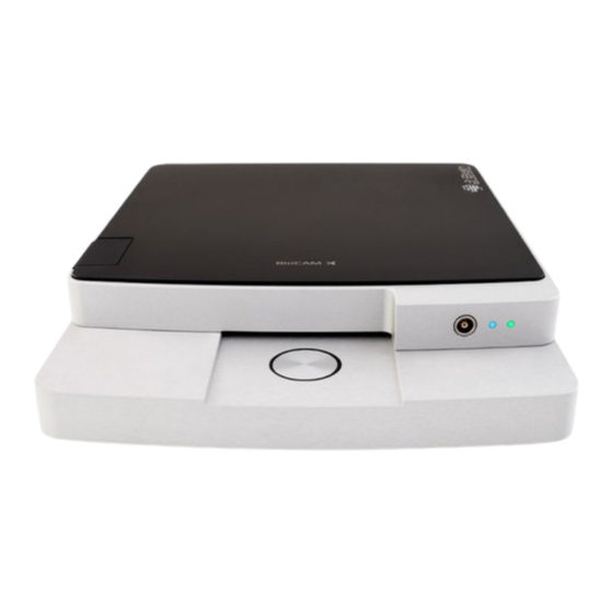
Page 11: Biocam X
• Lock button : two-position button for locking (end position) or unlocking (mid position) the BioChips. • BioChip bay : bay for inserting the BioChip and connecting it to the BioCAM X. • Magnetic plate : ferromagnetic stainless steel to attach magnetic holders (e.g., for perfusion). - Page 12 • Reference connector : connector for the pseudo-reference electrode that need to be placed in the bath solution of the BioChip cartridges. • LED1 : a solid blue LED indicates whether the BioCAM X is powered (LED ON) or not (LED OFF). A sol- id violet LED indicates a failure in BioCAM firmware. In addition, the LED1 blinks violet to indicate that the temperature control is ON.
-
Page 13: Host Pc
Host PC Depending on your order the host PC can be a desktop PC or a laptop. The way the BioCAM X instru- ment is connected to the host PC changes according to these two cases. Desktop PC When connected to a desktop workstation, the connection is direct between the BioCAM X and the host PC that is equipped with a Camera Link acquisition board. The typical configuration is as follow... -
Page 14: Brainwave X
BrainWave X BrainWave X is a complete software application developed to exploit all the functionalities of your BioCAM X platform. It is equipped with advanced tools adapted to manage high-resolution electro- physiological data acquired from BioChips. When launched it appears as follows (without experiments ongoing). Workspace Main Menu Tool Bar Panels Left Status Bar Right Status Bar • Main Menu : access main functions by clicking on the main menu. •... -
Page 15: Precautions
Precautions... -
Page 16: Biocam X Handling And Use
1. Immediately switch OFF the BioCAM and remove the BioChip. 2. Clean accurately the BioChip Bay of the BioCAM X with ethanol 96% and let it dry. Execute the same procedure for all the BioChip parts but for the BioChip reservoir and in particular for the BioChip con- nector pads. -
Page 17: Biochip Handling And Use
96% and let it dry for few seconds. • Avoid liquids to spill out and strictly avoid liquids to enter in contact with the pads (the BioCAM sys- tem is equipped with a Bay Barrier to protect the connecting socket). In case users experience liquid spill out, follows instructions provided in the “BioCAM X handling and use” section. In order to ensure a good quality of the recordings: • Avoid using HEPES (4-(2-hydroxyethyl)-1-piperazineethanesulfonic acid) in the solutions used for electrophysiological recordings, since we observed that it can interfere with the electrodes making the chip unstable and the recordings very noisy. -
Page 18: Cleaning Procedure For Biochips
Cleaning procedure for BioChips Normal cleaning It is a good practice to clean the BioChips immediately after the experimental recordings both for cell cultures as well as brain tissues. First, rinse abundantly the BioChips with Double Deionized Water (DDW), then fill the chambers with a detergent as WPI-Enzol (WPI) or Terg-A-zyme (Alconox) and gently pipette for few seconds. Leave the detergent for few minutes (typically 3-5 min) and then pipette again. After the use of detergent, rinse the BioChips abundantly with DDW, then leave the chamber filled with DDW for 1-2 minutes and repeat this operation 3-4 times in order to assure to wash out completely the detergent. -
Page 19: Sterilization Procedure For Biochips
Sterilization procedure for BioChips As indicated in the previous section, BioChips cannot be put in autoclaves, ovens or under UV-light exposure for sterilization purpose. These procedures risk to deteriorate the chips resulting in not optimal recording performances and in a shorter lifetime. If still not done, perform a cleaning procedure as indicated in the “Cleaning procedure for BioChips”... -
Page 20: Get Started
Get started... -
Page 21: Install The Biocam X
Desktop host PC 1. Plug the power supply cable into the power port located in the back of BioCAM X and then connect the power supply into an electrical outlet. Switch ON the BioCAM X by pressing the power button on the back. -
Page 22: Plug The Biochip
BioChip. 2. Push the Lock button in the BioCAM X to its end position to lock the BioChip to the BioCAM X con- nector. On BrainWave X software the BioChip LED icon in the Device Status Bar should turn ON. -
Page 23: Set Up A Non Pre-Configured Host Pc
Verify proper functioning Once you have installed and turned on the BioCAM X, opened and updated BrainWave X on the host PC and positioned a BioChip together with the reference electrode (see above sections), you can easily verify the proper functioning of the system by the following check list: 1. -
Page 24: Quick Guide To Your First Use
Quick guide to your first use... -
Page 25: Basic Concepts
Basic concepts Visualization of data BrainWave X makes use of tools designed to manage high resolution data coming from CMOS-MEAs. This has been implemented by combining conventional approaches with innovative ones. In particular, since BioChips act as “cameras for extracellular electrophysiological potentials”, several functionalities were introduced following similar approaches as used in multimedia. -
Page 26: Mea Viewer Control
MEA Viewer control Electrodes integrated in the CMOS-MEA are referred in BrainWave as Channels (abbreviated Ch). A fundamental control to browse your data is the MEA Viewer MEA Viewer representation of the voltage values of the channels by a color map Hover and click to select channels. -
Page 27: Data Formats
BrainWave X works with two main file types although it can export data in other formats. Those two own file types are BRW- and BXR-files. Both file types are using HDF5 hierarchical data format (hdfgroup. org). You can easily open them within most operating systems (including Windows, Linux and Mac OS) and most used data analysis environments, such as, among others, Python, Matlab, Scilab, Octave and R. You can find detailed documentation on both data files on 3brain.com/downloads#documentation. BRW stands for Brainwave RaW data file and contains continuous or qua- si-continuous data streamed from the BioCAM. BRW files, according to your acquisition settings, can contain for instance raw data recorded from all the BioChip MEA channels or a temporal subset of those data. In what follows you will learn to record plain raw data file. -
Page 28: Online Mode (Record Mode)
Hence you should always backup your important data. For details on RAID configurations check https:/ /en.wikipedia.org/wiki/Standard_ RAID_levels. Before moving forward, follow all the steps detailed in “Install the BioCAM X” “Plug the BioChip”. Hence, make sure that the BioCAM and the BioChip are properly connected by checking that the corre- sponding LED icons in the BrainWave X’s Right Status Bar are turned ON (blue icon). -
Page 29: Visualize Live Data
Visualize live data To start an acquisition and visualizing data read out from the BioChip: 1. Click Play under the Commands panel to start the acquisition. The MEA Viewer starts refreshing and displaying data. 2. Click on the MEA Viewer to select individual channels or Shift-click to select more channels. For each selected channel a new chart is plotted on the right showing the voltage data being read out from that channel. -
Page 30: Biochip Calibration
BioChip Calibration In case you experience several electrodes with short or prolonged periods of time where no signal is visible, you may suffer signal saturation problems. In this case, follow these steps before proceeding on with recording data. A typical example of a chip with saturating behavior is illustrated in the image below. On the left, the MEA Viewer shows many deep blue colored pixels indicating not working channels while on the right typical raw data traces with short periods of saturation (top-left, top-right and bottom-left) or even with persistent saturation (bottom-right) are shown. -
Page 31: Record Live Data
Record live data Complete the steps to “Visualize live data” and then: 4. Click the browse button on the Info panel to choose the path where to save your data. Be aware that to safely record from high resolution MEA you need high performance hard disks. Hence, browse to a file located either on a high-end disk (e.g., SSD; solid-state drive) or on a disk pool configured with RAID 0 (striping). If your order included a pre-configured host PC, the disk partition where you should... -
Page 32: Offline Mode (Playback Mode)
Offline mode (Playback mode) The tutorial contained in this section is based on the demo file on dissociated neuronal cultures you can find on http:/ /www.3brain.com/downloads. Download that file and then extract it to a known location by using 7-Zip or WinRAR. Open recorded data Locate the demo BRW-file to open. Then to open it in BrainWave X do one of the following: • Choose File > Open, or • right-click on the Workspace > Open, or • press Ctrl+O, or • drag the file from Windows Explorer into BrainWave X, or • double-click on the file in Windows Explorer. A new offline Experiment opens as a tabbed document. The tab name is the name of the BXR-file as- sociated to the BRW-file. Since you have open a BRW-file and no BXR-file has still been created the tab name will be in the form “Untitled-X”, being X a progressive application session-wide number. Hence, if this is the first file you open in this session it will be named “Untitled-1”. -
Page 33: Quick Analysis And Save Of Results
Quick analysis and save of results As a first step, we perform a spike detection on the loaded data. Choose Analysis > Peak Detection from the Main Menu or alternatively press Ctrl+P. On the new opening window, simply leave the default parameters and click OK and then wait for the analysis to be accomplished. Once finished, the BXR-field in the Info panel turns yellow to indicate that there are unsaved data. To save data do one of the following: •... -
Page 34: Visualize Recorded Data
Visualize recorded data As a consequence of the analysis, notice that the Timeline bar is now filled with vertical lines whose col- ors indicate the degree of the overall detected activity (averaged on the entire MEA) along the temporal axis. A blue-color indicates a relatively low activity, while a red-color a relatively high activity around that time position. To browse your Experiment for signals: 1. -
Page 35: Understanding Main Controls Affecting Graphs
Understanding main controls affecting graphs MEA Viewer Bin setting = bin to integrate for colors = Charts’ overlay rectangle width Charts Time bin = Timeline cursor width = Charts width... -
Page 36: Create A Group Of Relevant Channels
Create a group of relevant channels You can create groups of channels according to your selection or a given statistical information. Here we create a group considering channels’ global mea firing rate (MFR) values. Global MFR is computed for each MEA channel as the number of detected spikes divided by the length of the recording (spk/s). To create a group of most relevant and active channels: 1. -
Page 37: Visualize Instantaneous Mfr
Visualize Instantaneous MFR In addition to the Global MFR it might be useful to observe the instantaneous MFR, which gives the trend of the MFR computing it on successive small temporal bins. To plot the Time MFR: 1. Right-click on Channel Selection panel then choose Select Channels Group > NewGroup to select all the channels belonging to the newly created channels group. -
Page 38: Visualize Raster
Visualize Raster The time raster is another common tool used to observe activity on your data. 1. Click on Raster tab A time raster chart is plotted. 2. Increase Bar width for the raster to 2pt in order to have a more defined raster. 3. -
Page 39: Troubleshooting
Troubleshooting... -
Page 40: Electrodes With No-Signal (Saturation)
Electrodes with no-signal (saturation) Symptoms Few electrodes in the array have either persistent or short periods with no visible signal. This effect is overall called saturation and in this section we will refer to its two possible subtypes: persistent satura- tion (i.e. a channel is always saturated and no signal is displayed) and jumping saturation (i.e. raw signal is affected by short periods of saturation typically of tens to hundreds of milliseconds). - Page 41 (as those that can be provided to- configured to work in such conditions. In such gether with the BioCAM X system). scenario several electrodes typically exhibit jumping saturation. If you cannot perform this operations, or if you need light on the BioChip (e.g.
-
Page 42: Biochip Not Properly Initialized
BioChip”) was in the unlocked state when Chip is properly inserted till the end of its bay acquisition was initiated. and push the Lock button of the BioCAM X to its end position (see section “Plug the BioChip” for more details). Make sure that the BioChip LED icon on the BrainWave’s Right Status Bar... - Page 43 BioCAM X bridge module, which is responsi- Take one BioCAM Contact Cleaner and follow ble to connect the BioChip to the BioCAM, is these instructions to try to clean the BioCAM X dirty or damaged. bridge module: 1. Soak the cleaner on the marked area with pure ethanol (>96%)
-
Page 44: Not Working Columns
Causes One or more of the lines that go from the BioChip to the BioCAM X exhibit a faulty connection. This issue typically occurs between the BioChip contact pad(s) and the BioCAM X bridge module integrated inside the mechanical locking system. -
Page 45: Biochip With Dirty Surface
BioChip with dirty surface Symptoms This scenario can occur when testing a BioChip with no biological preparation. The chip might not have been properly cleaned or has not been used for a long period. In this situation, several electrodes on the array could exhibit either higher level of noise or signals with fake peaks.
Need help?
Do you have a question about the BioCAM X and is the answer not in the manual?
Questions and answers