Table of Contents
Advertisement
Advertisement
Table of Contents

Summary of Contents for LaserMech FiberCUT 2D
- Page 1 FiberCUT ® Operation Manual...
- Page 2 Inc. authorized personnel. ® Laser Mech is a registered trademark of Laser For complete warranty information visit our web site Mechanisms, Inc. at www.lasermech.com. ® PLMNL0232 REV. H Effective Date: 01/14/19 FiberCUT 2D Operation Manual...
- Page 3 INITIAL INSPECTION TERMS USED IN THIS MANUAL Inspect all shipping containers for damage as soon WARNING: The user could be injured as the device arrives. It is your responsibility, the if the warning is not followed. recipient, to notify the freight company of any damage.
-
Page 4: Table Of Contents
TABLE OF CONTENTS Introduction ................................7 Mechanical Installation and Operation ......................8 Machine Mount ........................... 8 Fiber Input and Installation ......................... 8 2.2.1 Upper Fiber Clamp ......................9 2.2.2 Fiber Orientation Adjustment ..................10 Plumbing – Water Cooling / Purge Gas / Assist Gas / Nozzle Cooling / Air Blast ......12 Beam Centering .......................... - Page 5 FiberCUT ® 2D Settings ........................30 4.4.1 Unlock Settings ......................30 4.4.2 Aux Output ........................30 4.4.3 HSU Curve ........................31 4.4.4 Pressure ........................31 4.4.5 Temperature Limits ....................... 33 4.4.6 Focus Position ....................... 34 4.4.7 Process Monitor Gain ....................34 4.4.8 Configuring EtherNet/IP Settings (If Equipped) ............
- Page 6 Specifications ..............................52 Troubleshooting .............................. 53 Appendix A – Coolant Specifications ......................54 Appendix B – Assist Gas Specifications ...................... 54 10 Appendix C – Beam Delivery Purging ......................54 11 Appendix D – Nozzle Cooling and Air Blast Specifications ............... 54 12 Appendix E –...
-
Page 7: Introduction
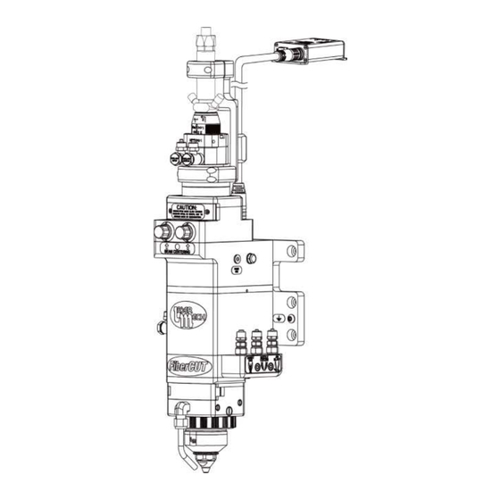
1 Introduction ® The FiberCUT 2D laser processing head was developed to provide cutting-edge performance for flatbed systems. Features of the FiberCUT ® 2D include the following (see Figure 1): Mounting plate with grounding lug Automatic programmable focus with 27 mm of travel ... -
Page 8: Mechanical Installation And Operation
2 Mechanical Installation and 2.2 Fiber Input and Installation Operation The fiber input adapter is where the fiber 2.1 Machine Mount optic cable plugs into the cutting head. See Figure 1. There are several standard types The mount plate attaches directly to your 3- of industrial fiber (QBH/HLC-8, QD/LLK-D/ axis machine according to Figure 2. -
Page 9: Upper Fiber Clamp
For steps 8 to 10, see Figure 4. 2.2.1 Upper Fiber Clamp 8. Align the upper fiber clamp so: The fiber clamp provides added stability to the fiber connection. The (2) alignment holes are in-line with the alignment It is necessary to remove the upper pins in the fiber clamp body. -
Page 10: Fiber Orientation Adjustment
2.2.2 Fiber Orientation Adjustment For steps 5 to 7, see Figure 6. If the water cooling fittings on the 5. Loosen, but do not remove, the fiber interfere with the fiber clamp (4) M4 SHCS in the round base. body, it is necessary to rotate the 6. - Page 11 For steps 8 and 9, see Figure 5. 10. Verify the gap between the lower fiber clamp and the fiber 8. Align the lower fiber clamp so: clamp body is the same on both sides of the lower fiber clamp. It is centered between the water cooled fiber interface adapter and the fiber clamp...
-
Page 12: Plumbing - Water Cooling / Purge Gas / Assist Gas / Nozzle Cooling / Air Blast
2.3 Plumbing – Water Cooling / Purge Purge gas specifications are in Gas / Assist Gas / Nozzle Cooling Appendix C. / Air Blast Air blast and nozzle cooling See Figure 7 and Figure 8 for line specifications are in Appendix locations. -
Page 13: Beam Centering
250X Digital USB Microscope software or equivalent. 1. Download and install the latest version Plugable 250X Digital USB Microscope software to the appropriate computer. http://www.lasermech.com/productupdates The Plugable.com website also has the software available to download and videos with more details on the features and uses of the microscope. - Page 14 The image on the screen 8. Rotate the brightness knob and should be similar to Figure adjust the camera to full brightness (see Figure 9). If it is too bright, rotate the brightness knob slightly, to suit. 9. Rotate the camera focus knob (see Figure 9) until the end of the gas jet tip becomes in focus with a clear image.
- Page 15 If necessary, it is possible to make If the beam is not centered, small adjustments to center the continue to step 11. beam by moving the collimator See Figure 14. body. If desired, move the collimator body slightly in the X and/or Y direction.
-
Page 16: Manual Beam Centering
2.4.2 Manual Beam Centering To manually center the beam in the gas jet tip: The beam must be aligned parallel and centered through the head. 1. Verify that the high power beam is disabled. Check the beam alignment 2. Put a piece of translucent tape during initial installation or on the end of the gas jet tip. -
Page 17: Electrical Installation And Operation
3 Electrical Installation and 1. Insert the female end of the control Operation cable into the cutting head. See Figure 17. The FiberCUT ® 2D has a companion control box that acts as the interface between the For steps 2 to 6, see the chart below for ®... - Page 18 Generation 1 Control Box Generation 2 Control Box Figure 18 Figure 19 ® PLMNL0232 REV. H Effective Date: 01/14/19 FiberCUT 2D Operation Manual...
-
Page 19: Generation 1 Controllers
3.2 Generation 1 Controllers 3.2.1 Interface Example The control box interface allows control and feedback of all the FiberCUT ® 2D operations. Controller Description The interface example in Figure 20 PLCSA0041 PROFINET is applicable for the following Generation 1 Laser Mechanisms’ PLCSA0052 EtherNet/IP controllers:... -
Page 20: Terminal Block Connections
3.2.2 Terminal Block Connections There are 3 analog outputs (HSU, Aux and Process) available through the terminal block connection. Each analog signal is referenced to Ground. ANALOG OUTPUTS OUTPUT DESCRIPTION The HSU output is a signal (0-10V) indicating the standoff distance of the tip and the part. -
Page 21: Generation 2 Controllers
3.3 Generation 2 Controllers 3.3.1 Interface Example Controller Description The control box interface allows PLCSA0064 Discrete I/O with EtherNet/IP control and feedback of all the PLCSA0065 Discrete I/O with PROFINET FiberCUT ® 2D operations. PLCSA0066 Discrete I/O, no Industrial Ethernet The interface example in Figure 22 is applicable for the following Generation 2 Laser Mechanisms’... -
Page 22: Terminal Block Connections
There is one analog input 3.3.2 Terminal Block Connections (Lens In) available through the There are 3 analog outputs terminal block. (HSU, Aux and Process) ANALOG INPUT available through the terminal block connection. INPUT DESCRIPTION Each analog output signal is The Lens In signal (0-10V) is used referenced to Ground. -
Page 23: Industrial Ethernet Connection
3.3.4 Machine Sequence to Move the There are 3 digital inputs (Cal, Lens to the Desired Location Reset and Move) available through the terminal block Section 3.3.2 for more connection. details on the inputs and outputs. DIGITAL INPUTS 1. -
Page 24: Control Box Mounting
3.4 Control Box Mounting The indicator light labeled READY is illuminated in green when the READY The control box mounting pattern is output is active. The light illuminates illustrated in Figure 24. Important things to in red when a fault is detected within consider when mounting the control box: the head. -
Page 25: Electrical Grounding And Noise
During normal operation, the indicator lights respond 3.6 Electrical Grounding and Noise as follows: The capacitive height sensing circuitry LED A ® contained in the FiberCUT 2D cutting STATE STATUS head measures small changes in electrical Green Module connected to a network capacitance between the tip and earth- Green and ground to determine tip-to-part standoff... -
Page 26: Fibercut Monitor
® FiberCUT Updates web page: ® and head temperatures of your FiberCUT http://www.lasermech.com/fibercut2dupdates on a single, easy-to-read screen. See Figure Once the compressed folder is downloaded from the web site it only needs to be decompressed. 1. Right-click on the compressed folder and select Extract All.. -
Page 27: Installing Fibercut 2D Driver
The display is a list of all the devices installed. ® 4.3 Using FiberCUT Monitor 2. Right-click on “FIBERCUT 2D I/O” and select “Update Driver 4.3.1 Start Up Software…” 1. Verify that all cables are 3. Click on “Browse my computer connected to the head and for driver software”. -
Page 28: System Controls
For steps 2 and 3, see Figure 29. 1. Click the following, as necessary: 2. Click on the Port drop down menu in the upper left corner Click the Reset button to and choose the appropriate move the lens to the zero port. -
Page 29: Faults And Status Indicator
The Main screen displays the current value of: Standoff Height Focus Position Temperature for electronics, both cover glasses, process monitor, focusing lens, and nozzle Purge gas pressure 4.3.3 Faults and Status Indicator See Figure 30 (the Main screen). When a fault occurs, the Ready output turns off and the corresponding light on the control box turns red. -
Page 30: Fibercut 2D Settings
The status indicator may also show that the head is Not Ready if the head is operating normally but is not ready for laser processing, such as when the HSU is calibrating. The on-screen Ready indicator may not change during some operations due to the software refresh interval. -
Page 31: Hsu Curve
If Fixed Voltage is selected, the screen shown in Figure 34 will appear. Figure 34 3. Enter the desired value within the stated range in the provided field. 4. Click OK to apply the settings. Figure 35 The current Aux Out fixed Load Curve and HSU voltage is displayed, if Parameters are advanced... - Page 32 Figure 37 Pressure readings outside the acceptable range result in a fault Figure 36 condition. The calibration function is also To Disable or Suppress the available through the Industrial Low Purge Fault Ethernet interface (see Appendix To disable faults generated by a purge pressure reading The acceptable minimum and below the lower limit...
-
Page 33: Temperature Limits
Temperature readings outside the acceptable range will result in a fault condition. To modify the desired upper temperature limit: 1. Click the Settings menu in the upper left corner of the Main screen and hover over Temperature Limits. Click on the desired temperature range to set. -
Page 34: Focus Position
A screen similar to Figure 42 The current upper temperature limit is will appear. displayed. The temperature upper limit must be within the stated range. Click Use Defaults to set all temperature limits to their maximum possible values. 4.4.6 Focus Position The Focus Position provides an on- Figure 42 screen reference between the... -
Page 35: Configuring Ethernet/Ip Settings (If Equipped)
4.4.8 Configuring EtherNet/IP Settings (If Equipped) ® FiberCUT 2D control boxes are set by default to use DHCP for Ethernet/IP communications. A static IP address can be set using ® FiberCUT Monitor. 1. Click the Settings menu in the upper left corner of the Main screen and select Ethernet/IP…... -
Page 36: Fibercut Monitor System Identification Information
® 4.5 FiberCUT Monitor System Identification Information The hardware, controller, interface, and HSU are all specific to your system. So, version and serial numbers are critical in order for Laser Mechanisms to provide support. To display system information: 1. Click the Display menu in the upper left corner of the Main screen and select …... -
Page 37: Service
5 Service Routine maintenance and service is required for If you removed all of the debris and ® the FiberCUT 2D Head. The operating dust from the outside of the head, the environment has a critical impact on the process is complete. -
Page 38: Servicing The Cover Glasses
® The FiberCUT 2D has an upper and a To replace the gas jet nozzle tip: lower cover glass. See Figure 51. For steps 3 and 4, see Figure 50. A. The lower cover glass is behind a sealed door, just below the focusing 3. -
Page 39: Servicing The Lower Cover Glass
Figure 52 For steps 4 to 12, see Figure 53. 4. Grasp the handle on the cover glass drawer and pull it straight out to remove it from the head. 5. Close the sealed cover glass door during service to keep contaminants out. - Page 40 7. Remove the cover glass from the drawer by applying pressure with your fingers to the surface of the cover glass, opposite the seal. The seal ring and cover glass will pop out. Inspect the seal ring. There MUST be NO dirt, process debris or any type of contamination on the seal.
-
Page 41: Servicing The Upper Cover Glass
5.3.2 Servicing the Upper Cover Glass For steps 4 to 7, see Figure 55. 4. Protect the cover glass with REMOVING THE UPPER blue painter’s tape, or COVER GLASS DRAWER equivalent, and take to a clean RUNS THE RISK OF THE area. -
Page 42: Servicing The Breakaway Insulator
5.4 Servicing the Breakaway 7. Press the seal ring into the Insulator drawer to retain the cover glass. The tip assembly contains an internal breakaway insulator (PLISR0041) that fractures to protect the head during a crash. See Figure 56. The tip assembly nut will remain threaded on the head. - Page 43 4. Remove the (6) M3 SHCS that secure 1. Gather the tip assembly if it was the broken breakaway insulator to the fractured from the head. tip assembly. See Figure 58. For steps 2 and 3, see Figure 57. 5. Remove the breakaway insulator with the o-rings.
-
Page 44: Servicing The Tip Assembly
7. Install a new breakaway insulator into 5.5 Servicing the Tip Assembly the tip assembly nut so the counterbores are facing up. See Figure 60. 8. Orient the alignment pin in the tip To remove: assembly so it is in-line with the 1. -
Page 45: Servicing The Focus Lens
5.6 Servicing the Focus Lens Before opening any part of the head, clean off the dust and/or process debris according to Section 5.1. DO NOT BLOW OFF THE HEAD WITH COMPRESSED AIR! To change the focus lens, the tip assembly and manifold block must be removed and relocated to a clean dry area. -
Page 46: Adjusting The Focus Lens Position Manually
11. Install the tip assembly according to Section 5.5. 12. Verify beam centering according to Section 2.4. Adjust the beam as necessary using the beam centering knobs. See Figure 11. It should not be necessary to make any adjustments along the X-axis or Y-axis. -
Page 47: Removing The Cutting Head And Fiber
2. Insert the longer end of a 3 mm hex 5.8 Removing the Cutting Head and wrench in the location shown in Figure Fiber 64 to engage and adjust the lens ball Before opening any part of the screw. head, clean off the dust and/or ... - Page 48 7. Position the head so it is 6. Unbolt the head from the machine HORIZONTAL. See Figure 66 . using a 6mm hex wrench as shown in Figure 65. Figure 66 8. Verify the fiber and connector are thoroughly clean. 9.
-
Page 49: Servicing The Collimator Lens Cartridge
For steps 16 and 17, see Figure 65. The open area of the fiber receiver MUST be covered. 16. Align the head so the M8 counterbore holes in the mount plate are in line with Use the manufacturer supplied the M8 tapped holes in the machine dust cap. - Page 50 2. Remove the (4) M2 SHCS and the 4. Remove the (4) M5 LHCS that secure electronics cover or cooling block from the collimator and remove it from the the collimator. head. Verify the gasket is in the groove 5.
- Page 51 For steps 6 to 8, see Figure 70. If you have the standard electrical box cover, see Figure 68 for steps 9 to 13. 6. Use lens insertion tool (PLLIT0034) to unthread the collimator lens cartridge If you have the optional collimator and shim(s) from the collimator.
-
Page 52: Specifications
6 Specifications CUTTING HEAD Power Rating ..........................up to 8 kW Focusing Lens (Nominal Focal Length) ............125 mm, 150 mm, 200 mm Focusing Lens (Diameter) ......................38.1 mm Clear Aperture ........................... 35 mm Nozzle Tip ....................Various Shapes and Orifice Sizes Assist Gas Pressure .................... -
Page 53: Troubleshooting
7 Troubleshooting SYMPTOM CAUSE REMEDY Verify that the tip assembly and HSU Fault: There is no connection between the HSU internal sense cables are properly 1: Tip Open and tip assembly during calibration. installed and then recalibrate. The tip is not fully insulated from ground Remove any debris that may be HSU Fault: and the body of the cutting head during... -
Page 54: Appendix A - Coolant Specifications
8 Appendix A – Coolant Specifications The cooling manifolds are designed to be operated on either a closed-loop cooling system or facility tap water. For either type of system, the requirements in the table below must be met. Minimum Flow Rate 1.5 liter/minute @ 2 BAR minimum Inlet Pressure 5.0 Bar (72.5 psi) Max... -
Page 55: Appendix E - Industrial Ethernet Data Mapping And Descriptions
Device Anybus-IC EIP Name Exclusive Owner Input 17 INT, Connection Point 100 Output 6 INT, Connection Point 150 The EDS file is available for download at http://www.lasermech.com/fibercut2dupdates WORD TYPE NAME Input Data Digital Outputs Input Data HSU Voltage Input Data... -
Page 56: Profinet I/O Mapping
12.2 PROFINET I/O Mapping ITEM DESCRIPTION Device Name ABIC-PRT The GSDML file is available for download at http://www.lasermech.com/fibercut2dupdates SLOT MODULE NAME Input 001 byte Fault Digital Outs Input 001 byte Status Digital Outs Input 002 bytes HSU Voltage Input 002 bytes... -
Page 57: Input, Output, And Other Descriptions
12.3 Input, Output, and Other Descriptions Digital Output Descriptions OUTPUT DESCRIPTION No Comm. The head is not communicating with the controller. Check connections or cycle power. The value in the Set Position register is beyond the movement range of the lens or the Position Error lens cannot move due to a Lens Fault. - Page 58 Other Descriptions DATA DESCRIPTION HSU Voltage The 12 bit ADC voltage output of the HSU. Process Monitor The 12 bit ADC voltage output of the process monitor. The pressure (in millibars) within the purge path relative to the programmed ambient Purge Pressure pressure.
-
Page 59: Appendix F - Recommended User-Serviceable Parts List
13 Appendix F – Recommended User-Serviceable Parts List For recommended user-serviceable spare parts, please call Laser Mechanisms at (248) 474-9480. If your head requires service beyond the instructions outlined in this manual, please contact Laser Mechanisms for further assistance. ITEM PART # DESCRIPTION 1080 nm Applications... - Page 60 ITEM PART # DESCRIPTION STANDARD NOZZLES (Call Laser Mechanisms for more options) GAS JET TIPS PLGJT0058 1.0 mm Orifice PLGJT0261 1.2 mm Orifice PLGJT0039 1.5 mm Orifice PLGJT0098 2.0 mm Orifice PLGJT0168 2.5 mm Orifice PLGJT0138 3.0 mm Orifice PLGJT0737 3.5 mm Orifice PLGJT0595 4.0 mm Orifice...
- Page 61 Figure 71 ® PLMNL0232 REV. H Effective Date: 01/14/19 FiberCUT 2D Operation Manual...
-
Page 62: Appendix G - Servicing The Tip Assembly
14 Appendix G – Servicing the Tip Assembly 14.1 Rebuilding the Tip Assembly To disassemble the tip assembly: 9. Inspect the small o-ring (PLMOR0039) 1. Remove the tip assembly from the near the bottom of the 2.5 mm head according to Section 5.5. - Page 63 To reassemble the tip assembly: Worn or damaged o-rings were replaced during the disassembly procedure. Replace any other worn or damaged components during the reassembly procedure. For steps 17 to 28, see Figure 72. 17. If necessary, replace the gas jet tip and/or tip retainer nut assembly according to Section...
- Page 64 23. Insert the upper insulator 26. Insert the breakaway insulator (PLISR0042) so that the smaller gold (PLISR0041) into the retainer nut. post is aligned with the upper insulator 27. Align the breakaway insulator and hole. retainer nut so that the breakaway ...
-
Page 65: User Serviceable Parts List
14.2 User Serviceable Parts List For recommended user-serviceable spare parts, please call Laser Mechanisms at (248) 474-9480. If your head requires service beyond the instructions outlined in this manual, please contact Laser Mechanisms for further assistance. ITEM PART # DESCRIPTION PLTRA0447 Tip Assembly (Complete Assembly) PLSCR0109... -
Page 66: Appendix H - Maintenance
15 Appendix H – Maintenance COMPONENT FREQUENCY DESCRIPTION Water & Gas After performing any Inspect and replace any worn or damaged hoses. Lines maintenance Section 2.3 for more details. Nozzle After a Nozzle Change Inspect and adjust as needed according to Section 2.4. -
Page 67: Glossary
16 Glossary Aiming Beam A low power, visible red beam used to indicate Height Sensing Unit the position of the high-powered laser beam. Assist Gas Integrated Circuit Coaxial gas that flows through the nozzle (gas jet tip) orifice to aid the cutting process and evacuate molten material from the kerf. - Page 68 Laser Mechanisms, Inc. 25325 Regency Drive • Novi, Michigan 48375 USA Phone: (248) 474-9480 • Fax: (248) 474-9277 In Europe: Phone: +32(0)92 18 70 70 • Fax: +32(0)92 18 70 79 Web: www.lasermech.com • E-Mail: info@lasermech.com...
Need help?
Do you have a question about the FiberCUT 2D and is the answer not in the manual?
Questions and answers