Table of Contents
Advertisement
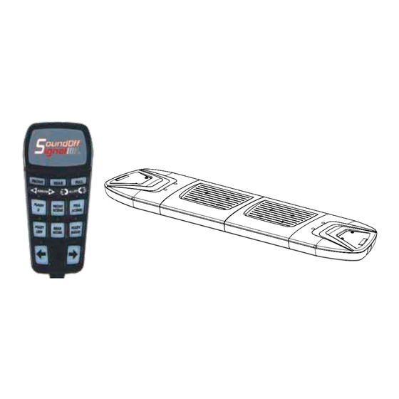
Exterior Lightbar Connect-n-Go System
9
8
G
F
E
D
IMPORTANT NOTICE TO INSTALLER: Make sure to read and understand all instructions
C
and warnings before proceeding with the installation of this product. Ensure that
the manual and any warning cards are delivered to the end user of this equipment.
Proper installation of the lightbar requires the installer to have a thorough knowledge of
B
automotive electronics, systems, and procedures. Lightbars provide an essential function
of an effective visual warning system. The use of the lightbar does not insure that all
drivers can or will abide by or react to an emergency warning signal, especially at high
A
9
8
rates of speeds or long distances. The operator of the vehicle must never take the right of
way for granted and it is the operator's responsibility to proceed safely. The effectiveness
of the lightbar is highly dependant on the correct mounting and wiring. The installer must
read and follow the manufacturer's installation instructions and warnings in the manual.
The vehicle operator should verify daily that the lightbar is securely fastened to the vehicle
and properly functioning before operating vehicle. The lightbar is intended for use by
authorized personnel only. It is the user's responsibility to ensure they understand and
operate the emergency warning devices in compliance with the applicable city, state and
federal laws and regulations. SoundOff Signal assumes no liability for any loss resulting
from the use of this warning device.
COMPONENTS/ CONTENTS
Standard Equipment:
1 - nROADS Fleet® LED Lightbar, built to your specifications
1 - Handheld Controller
Other Parts that May Be Included Depending on Your Configuration:
1
- Vehicle Specific Hook Kit w/ Hardware*
2
- Fixed Height Mounting Brackets w/ Hardware
1
- Flat Mount Hardware Kit or
2
- Headache Brackets w/ Hardware
*Kits will vary with each lightbar, depending on vehicle specified on order form.
Compatible Lights with This System (Ordered Separately):
2 or 4 - 4" mpower® Fascia Lights
Unpack Lightbar
1. Remove the lightbar from box and packaging.
2. Save packaging for later shipping.
3. Check components/ contents.
4. Please reference these instructions for proper wiring and installation.
1.800.338.7337 / www.soundoffsignal.com
Installers and users must comply with all applicable federal, state and local laws regarding use and installation of warning devices. Improper use or installation may void
warranty coverage. To review our Limited Warranty Statement & Return Policy for this or any SoundOff Signal product, visit our website at www.soundoffsignal.com/sales-
support. If you have questions regarding this product, contact Technical Services, Monday - Friday, 8 a.m. to 5 p.m. or after hours 5 p.m. to 8 p.m. EST at 1.800.338.7337 (press
#4 to skip the automated message). Questions or comments that do not require immediate attention may be emailed to techservices@soundoffsignal.com.
S U P E R I O R C U S TO M E R R E L AT I O N S H I P S . S M A RT LY D E S I G N E D L I G H T I N G & E L E C T R O N I C S O L U T I O N S .
1.
7
6
5
7
6
5
https://www.soundoffsignal.com/products/nroads-fleet-cng-lightbar/
4
3
2
PAGE
1
2
3
4
FIXED HEIGHT BRACKETS AND HOOK MOUNTING
5
6,7
8,9
PROPRIETARY AND CONFIDENTIAL
THE INFORMATION CONTAINED IN
THIS DRAWING IS THE SOLE
PROPERTY OF SOUNDOFF SIGNAL.
ANY REPRODUCTION IN PART OR
®
AS A WHOLE WITHOUT THE
TOLERANCES
WRITTEN PERMISSION OF
SOUNDOFF SIGNAL IS PROHIBITED.
EXCEPT AS NOTED
.X
± .020
THIRD ANGLE
.XX
± .012
CAD DIMENSIONS ARE BASIC
10-12
PROJECTION
.XXX ± .006
UNLESS OTHERWISE SPECIFIED
ANGLES ± .5°
DRAWING
B
PRIMARY DIMS: INCH
GD&T TO FOLLOW
SIZE:
DUAL DIMS: [mm]
ASME Y14.5M-1994
DO NOT SCALE
MATERIAL:
DESCRIPTION:
MESA LIGHT BAR ASSEMBLY
13
WIRING & HANDHELD BUTTON ASSIGNMENT
DRAWING NO:
MESA_LIGHT_BAR_ASSEMBLY-INSTALL.SHEET.UPDATES
4
3
2
14
15
DRIVER MODULE/ MPOWER® REPLACEMENT
16
17,18
19
WARRANTY AND RETURN GOODS PROCEDURE
Important Information:
• Warning devices are strictly regulated and governed by Federal,
State and Municipal ordinances. These devices shall be used
ONLY on approved vehicles. It is the sole responsibility of the
user of these devices to ensure compliance.
• DO NOT install this product or route any wires in the air bag
deployment zone. Refer to your vehicle owner's manual for the
location of any air bag deployment zones.
• DO NOT connect this device to a strobe power supply. This
product is self-contained and does not require an external
power supply.
This product contains high intensity LED devices. To
NOTICE:
For Quick Install Video please visit:
TABLE OF CONTENTS
1
G
CONTENT
F
COMPONENTS/ CONTENTS
MODULE SPECIFICATIONS
E
TECHNICAL/ POWER SPECIFICATIONS
D
GASKET MOUNTING INSTRUCTIONS
C
ELECTRICAL INSTALLATION
MPOWER® INSTALLATION
B
FLASH PATTERNS & CONFIGURATIONS
A
REVISION:
1 OF 3
SHEET
1
LIGHT MODULE WIRE HARNESS LOCATIONS
CONNECT-N-GO SYSTEM TROUBLESHOOTING
REPLACEMENT PARTS
WARNING
!
prevent eye damage, DO NOT stare into the light
beam at close range.
nROADS Connect-n-Go 1018
Advertisement
Table of Contents

Summary of Contents for Soundoff Signal nROADS Fleet Series
- Page 1 Installers and users must comply with all applicable federal, state and local laws regarding use and installation of warning devices. Improper use or installation may void warranty coverage. To review our Limited Warranty Statement & Return Policy for this or any SoundOff Signal product, visit our website at www.soundoffsignal.com/sales- support.
-
Page 2: Module Specifications
Exterior Lightbar Connect-n-Go System MODULE SPECIFICATIONS 6 LED Single & 12 LED Dual Color Inboard Module INPUT VOLTAGE RANGE: 10-16Vdc CURRENT DRAW: 0.2 Amps (Flashing) / 0.4 Amps(Steady On) POWER @ 12.8Vdc: 2.6W (Flashing) / 5.2W (Steady On) 9 LED Single & 18 LED Dual Color Inboard Module INPUT VOLTAGE RANGE: 10-16Vdc CURRENT DRAW: 0.3 Amps (Flashing) / 0.6 Amps (Steady On) -
Page 3: Bottom View
TECHNICAL SPECIFICATIONS Exterior Lightbar Connect-n-Go System Aluminum Base, polycarbonate Material: outer lenses, ASA/PC top cover. Roof Attachments: 1/4" bolt Stainless A2 Operating Temperature: -40º to +65º C TOP VIEW WITH COVERS ON LENGTH # OF INBOARDS DIMENSIONS 36" 42" 12"D x 2.5"H 48"... - Page 4 FIXED HEIGHT BRACKETS AND HOOK MOUNTING (NON-PURSUIT) Exterior Lightbar Connect-n-Go System 1. Keeping the lightbar level with the road, attach mounting feet to the roof of the vehicle using the supplied T-bolts. If the vehicle is pursuit rated, there will be 8 supplied T-bolts.
- Page 5 Exterior Lightbar Connect-n-Go System GASKET MOUNTING INSTALLATION REAR 1. Install the Grey gasket in the front slot of the lightbar, as shown in Fig 1. WIRE SLEEVE INSTALLATION 1. Unspool all harnesses coming out of the lightbar. 2. Feed all harnesses through the sleeve until the sleeve is positioned at the exit hole under the lightbar.
-
Page 6: Electrical Installation
Exterior Lightbar Connect-n-Go System ELECTRICAL INSTALLATION Featured Highlights & Terminology: Directional Arrow Built-in: The directional controller is built-in with 11 patterns for each of the 3 modes (left arrow, right arrow, and center out arrow) and the color is selectable for dual color bars. Scene Light Mode: Allows the user to program any light head group(s) to turn on steady when this feature is activated to provide additional scene lighting. - Page 7 Exterior Lightbar Connect-n-Go System ELECTRICAL INSTALLATION (CONT.) Initial Setup of mpower® Fascia Lights (2 Front and 2 Rear): The Connect-n-Go mpower® modules will automatically sync with the nROADS® Fleet Lightbar. To ensure the mpower® modules are synced properly based upon where they are mounted, perform the following steps: 1.
-
Page 8: Installation
Exterior Lightbar Connect-n-Go System INSTALLATION: Stud Mount (Figure 1) 1. Pre-Drill per stud mount pattern indicated on page 9, per the supplied mounting template. 2. Clean the surface as required. 3. Deburr hole as required. 4. Feed wire through the drilled wire hole and make mating plug connection. FASCIA LIGHTS - 4”* 5. -
Page 9: Screw Mount
QUICK MOUNT, 4" Exterior Lightbar Connect-n-Go System FASCIA LIGHTS - 4” TEMPLATE 4" SCREW MOUNT SCREW MOUNT, 4" WIRE THRU-HOLE 7/16 11.00 DRILL 4" SCREW MOUNT 2.15±0.01 2.15±0.01 54.50±0.25 54.50±0.25 2X DRILL INSERT HOLES 0.04±0.01 1.00±0.15 STUD MOUNT, THREADED, 4" WIRE THRU-HOLE 7/16 DRILL... - Page 10 Exterior Lightbar Connect-n-Go System FLASH PATTERNS & CONFIGURATIONS Program 1 - Flash Patterns 1: 1. Press and hold buttons 1 and 2 for 5 seconds. 2. The arrow left and arrow right indicators will flash and system will transition to warning flash mode 1 to indicate system is in this programming mode. 3.
- Page 11 Exterior Lightbar Connect-n-Go System FLASH PATTERNS & CONFIGURATIONS (CONT.) Program 7 – mpower® Fascia Flash Front Colors Selection: 1. Press and hold buttons 2 and 4 for 5 seconds. 2. The arrow left, arrow right, and alley left indicators will flash and system will transition to warning mode to indicate system is in this programming mode. 3.
-
Page 12: Flash Patterns
Exterior Lightbar Connect-n-Go System FLASH PATTERNS FLASH PATTERN INDEX GUIDE (BCD) Button(s) 1,2,3 1,2,4 FLASH PATTERNS: WARNING PATTERNS California Title 13 Name Compliant Sequence fpm* fps** Compliant Timing Timing Random #1 Variable Quint Alternating Quad 2 Variable Q-Switch Variable Double Alternating Power Pulse Alternating... - Page 13 Exterior Lightbar Connect-n-Go System HANDHELD WIRING & BUTTON ASSIGNMENT 15 Amp FUSE (Customer Supplied) GROUND POWER CABLE BLACK 12 GA. GROUND +12v Ignition Switch HANDHELD BUTTON ASSIGNMENT Button Function Operation FRONT Warning Front (Flash 1)* Latched REAR Warning Rear (Flash 1)** Latched FULL Warning Full (Flash 1)***...
- Page 14 Exterior Lightbar Connect-n-Go System LIGHT MODULE REPLACEMENT & WIRE HARNESS LOCATIONS REPLACEMENT OF INBOARD AND CORNER MODULES: 1. Disconnect main power. 2. Remove top cover by removing screws. 3. Locate module. If it has a bracket, remove the screw (if no bracket skip this step.) 4.
- Page 15 Exterior Lightbar Connect-n-Go System DRIVER MODULE REPLACEMENT Driver Module Replacement: 1. Verify power has been removed from light bar before attempting service. 2. Remove top cover. 3. Unplug 3 pin power/ data connector and LED module connectors from driver module assembly, noting location. 4.
- Page 16 Exterior Lightbar Connect-n-Go System CONNECT-N-GO SYSTEM TROUBLESHOOTING NORMAL OPERATION Under Normal Operation with light bar turned ON, the handheld controller will be backlit. NO OPERATION Controller backlight is green; Check input power and ground to lightbar, check data cable for damage and/or opens. Check Ignition Input wire and verify a minimum of 10.0 Volts is present on the wire.
-
Page 17: Replacement Parts And Accessories
Exterior Lightbar Connect-n-Go System REPLACEMENT PARTS & ACCESSORIES ITEM ITEM PART# DESCRIPTION PART# DESCRIPTION PNFLBK00 STANDARD FIXED HEIGHT MOUNT - THIN PAD PRMLBLS106(x) SINGLE COLOR 6 LED INBOARD MODULES PRMLBLS109(x) SINGLE COLOR 9 LED INBOARD MODULES PNFLBF00 FIXED HEIGHT PERMANENT MOUNT HOOK KIT PRMLBLD112(xx) DUAL COLOR 12 LED INBOARD MODULES PNFLBK02... - Page 18 Exterior Lightbar Connect-n-Go System REPLACEMENT PARTS & ACCESSORIES*** (CONT.) PRMLBHNPW2 CONNECT-N-GO 16' POWER/IGNITION HARNESS PRMLBHNXT1 CONNECT-N-GO 10' AUXILIARY EXTENSION HARNESS CONNECT-N-GO 16' AUXILIARY HARNESS with PRMLBHNPT3 JWPF CONNECTOR PRMLBDRV2 nROADS® CONNECT-N-GO POWER DISTRIBUTION BOARD mpower® 4" FASCIA LIGHT W/ QUICK MOUNT, FOR USE WITH CONNECT-N-GO, SAE CLASS 1 & CA TITLE 13, EMPSCG2QMS2(x)* 9-32VDC, BLACK HOUSING, 6 LED, SINGLE COLOR mpower®...
- Page 19 WARNING - DRILLING ANY HOLES INTO THE LIGHTBAR IS NOT SoundOff Signal will NOT accept returns without an RMA #. Each RMA # is good for only one (1) return and will expire (30) days after the date it was RECOMMENDED! THE RISK OF DAMAGING INTERNAL COMPONENTS issued.
Need help?
Do you have a question about the nROADS Fleet Series and is the answer not in the manual?
Questions and answers