Table of Contents

Summary of Contents for Ducati Energia DUCA-LCD96 Series
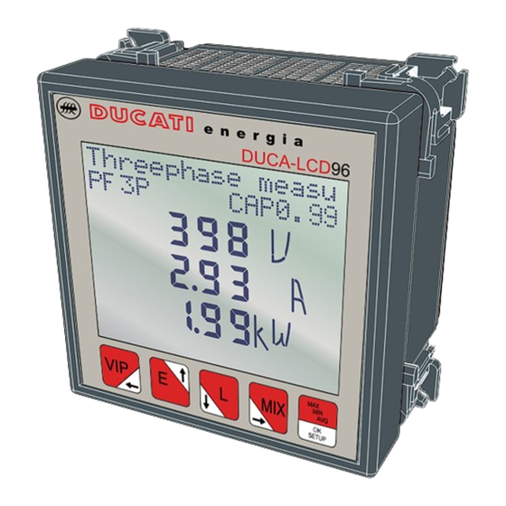
- Page 1 DUCA-LCD96 468001289 DUCA-LCD96 485 468001291 DUCA-LCD96-ETH 468001296 DUCA-LCD96-PROFI 468001294 DUCA-LCD96 485-RELE 468001293 DUCA-LCD96 485-IO 468001292 DUCA-LCD96 BASE 468001288 NETWORK ANALYSER Assembly and use instructions energia...
-
Page 3: Table Of Contents
CHAPTER energia SUMMARY 1 GENERAL INFORMATION Reference regulations and conformity............5 Use and storage of the manual ..............6 1.2.1 Storing .....................6 1.2.2 Copyright....................6 General safety warnings ................7 2 PACKAGING CONTENTS Removal of packaging ................8 Description of the contents ..............9 3 TECHNICAL CHARACTERISTICS Description of the device................10 Measuring functions ................10 Models ...................... - Page 4 CHAPTER energia SUMMARY 5.3.5 Digital output menu ................47 5.3.5.1 Digital output mode ..................47 5.3.5.2 Energy value for pulse ..................48 5.3.5.3 Alarm1 or alarm2(*) parameter ..............49 5.3.5.4 Alarm 1 or 2 threshold ..................50 5.3.5.5 Alarm 1 or 2 activation ..................50 5.3.5.6 Alarms 1 or 2 activation delay ..............51 5.3.5.7 Alarm 1 or 2 hysteresis .................51 5.3.6 Alarm output menu.................52 5.3.6.1 Alarm 3 or 4 parameter (*) ................52 5.3.6.2 Alarm 3 or 4 threshold ..................53 5.3.6.3...
-
Page 5: 1 General Information
CHAPTER energia GENERAL INFORMATION 1 GENERAL INFORMATION 1.1 Reference regulations and conformity 2006/95/CEE 93/68/CEE (Low-Voltage Directive). Electrical safety IEC 61010-1 Electromagnetic compatibility 89/336/CEE Use of hazardous substances UE 2002-95-CE – RoHS IEC 60688 IEC 61326-1 Measuring instruments IEC 62053-21 IEC 62053-23 IEC 62053-31 Degree of protection IEC 60529 Standardised dimensions for the panel IEC 61554 DUCA-LCD96... -
Page 6: Use And Storage Of The Manual
1.2.2 Copyright The copyright of this manual is the property of DUCATI Energia S.p.A. This manual contains texts, designs and illustrations of a technical nature which must not be disclosed or transmitted to third parties, even partially, without the written authorisation of DUCATI Energia S.p.A. -
Page 7: General Safety Warnings
CHAPTER energia GENERAL INFORMATION 1.3 General safety warnings Non-adherence to the following points can lead to serious injury or death. • Use the suitable personal protection devices and adhere to the current regulations governing electrical safety. • This device must be installed exclusively by qualified personnel who have read all of the information relative to the installation. -
Page 8: 2 Packaging Contents
CHAPTER energia PACKAGING CONTENTS 2 PACKAGING CONTENTS 2.1 Removal of packaging We recommend that the packaging is stored in a suitable location in compliance with the warranty terms DUCA-LCD96 NETWORK ANALYSER Rev. 1.0... -
Page 9: Description Of The Contents
CHAPTER energia PACKAGING CONTENTS 2.2 Description of the contents The packaging includes: network analyser user manual calibration certificate mini CD with technical documentation assembly accessories Prior to using the product read the documentation attached and strictly adhere to the indications provided. energia energia DUCA-LCD96 NETWORK ANALYSER Rev. -
Page 10: 3 Technical Characteristics
• system energy consumption. 3.2 Measuring functions All of the DUCA-LCD96 series models are able to measure and process the quantities shown below. Voltages (phase neutral and concatenated) and relative peak values; Currents and relative peak values; Power factors or PF phases and the 3-phase system, with distinction icon between the inductive and capacitive load;... -
Page 11: Models
CHAPTER energia TECHNICAL CHARACTERISTICS 3.3 Models Serial Models Inputs and outputs communication protocol 2 outputs programmable with pulses DUCA-LCD96 or threshold alarms 2 outputs programmable with pulses DUCA-LCD96 485 Modbus RTU or threshold alarms 2 outputs programmable with pulses DUCA-LCD96-ETH Modbus TCP/IP or threshold alarms 2 outputs programmable with pulses... -
Page 12: Overall Dimensions
CHAPTER energia TECHNICAL CHARACTERISTICS 3.4 Overall dimensions e n e r g i a DUCA-LCD96 SETUP 96 mm 77 mm 96 mm 57 mm 92 mm 20 mm IEC 61554 -0+0,8 -0+0,8 DUCA-LCD96 NETWORK ANALYSER Rev. 1.0... -
Page 13: Technical Data
CHAPTER energia TECHNICAL CHARACTERISTICS 3.5 Technical data Auxiliary power supply from 24 to 240 a.c./d.c. Voltage range from 48 to 240 a.c../d.c.DUCA-LCD96-ETH, DUCA-LCD96-PROFI, DUCA-LCD96 485-IO Frequency range [Hz] 45 ÷ 65 T 0,5 A from 24 V to 100 V Protection fuse T 0.25 A from 24 V to 100 V Power consumption [VA] 7 max... - Page 14 CHAPTER energia TECHNICAL CHARACTERISTICS Installation Low and medium voltage Singlephase insertion Distribution networks 3-phase with neutral 3-phase without neutral Always use external CT Primary from 1 to 10.000 A a.c. approx. Secondary 5 A and 1 A a.c. approx. Ammetric inputs N.B.: in case of CT secondary at 1 A the accuracy class is declassified to 2,5% F.S.
- Page 15 CHAPTER energia TECHNICAL CHARACTERISTICS Overall dimensions 96 mm x 96 mm x 77 mm (Depth inside switchboard: 57 mm) Weight [Kg] 0.400 max Standard normatives Overall dimensions IEC 61554 Degree of protection IEC 60529 IEC 60688, IEC 61326-1, IEC 62053-21 , Accuracy class IEC 62053-23, IEC 62053-31.
- Page 16 CHAPTER energia TECHNICAL CHARACTERISTICS Ethernet Protocol Modbus TCP/IP Connectors RJ45 Digital output programmed as pulse Contact supply external voltage [V] 48 max (peak ac/dc) Maximum current [mA] 100 (peak ac/dc) Pulse duration [ms] 50 OFF (min) / 50 ON closed contact Pulse frequency 10 pulses/s (max) Digital output programmed as alarm...
- Page 17 CHAPTER energia TECHNICAL CHARACTERISTICS Hour counters Count of the system operating time through the activation of a programmable threshold Count-down timer on total current. Upon expiry of the maintenance period set an icon will appear on the display. Count-up timer Life time of instrument Climatic conditions Storing...
-
Page 18: Installation
CHAPTER energia INSTALLATION 4 INSTALLATION 4.1 Assembly IEC 61554 DUCA-LCD96 NETWORK ANALYSER Rev. 1.0... -
Page 19: Disassembly
CHAPTER energia INSTALLATION 4.2 Disassembly DUCA-LCD96 NETWORK ANALYSER Rev. 1.0... -
Page 20: Wiring Diagrams
CHAPTER energia INSTALLATION 4.3 Wiring diagrams The operations to carry out for the correct connection of the device, based on the type of electric line available, are described in this section. The installation and the cabling of the device must be carried out by qualified personnel. - Page 21 CHAPTER energia INSTALLATION Max 500 V 24-240V| 24-240V| Max 500 V OUT2 | OUT1 OUT2 | OUT1 1 2 | 1 2 1 2 | 1 2 AC-DC AC-DC 48-240V| Max 500 V 48-240V| Max 500 V OUT2 | OUT1 OUT2 | OUT1 1 2 | 1 2 1 2 | 1 2...
-
Page 22: Wiring Diagrams
CHAPTER energia INSTALLATION 4.3.1 Wiring diagrams 3-phase + neutral with 3 CT and 3-phase + neutral with 3 CT 3 VT 3-phase with 3 CT Fuse Load TV3 TV2 TV1 DUCA-LCD96 NETWORK ANALYSER Rev. 1.0... - Page 23 CHAPTER energia INSTALLATION AARON 3-phase with 2 CT and 3 Balanced 3-phase with 1 CT Monophase with 1 CT Fuse Load TV3 TV1 Not suitable for the DUCA-LCD96 BASE. DUCA-LCD96 NETWORK ANALYSER Rev. 1.0...
-
Page 24: Inputs And Outputs Connections
CHAPTER energia INSTALLATION 4.3.2 Inputs and outputs connections Digital outputs as alarms with Electromechanical relay outputs external relay for loads command DUCA-LCD96 485-RELE Digital outputs as pulses V aux 48 V a.c./d.c. 100 mA Load 16A AC1 - 3A AC15 External relay V aux 250 V a.c. MAX Pulse acquisition DUCA-LCD96 NETWORK ANALYSER... - Page 25 CHAPTER energia INSTALLATION DUCA-LCD96 485-IO digital inputs DUCA-LCD96 485-IO analog (example in NPN mode) outputs G.M.C. + ES card Typical 250 Ohm load, max 600 Ohm V aux 24 V d.c. (32 V d.c. max) DUCA-LCD96 NETWORK ANALYSER Rev. 1.0...
-
Page 26: Configurations For First Use
CHAPTER energia INSTALLATION 4.4 Configurations for first use After having cabled the instrument according to the pre-selected layout, the following operations must be carried out to start to use the analyser: set the language (see paragraph “5.3.9 Language menu”) set the CT transformation ratio (see “5.3.4.2 Set CT ratio”) set the VT transformation ratio (see “5.3.4.3 Set VT ratio”) DUCA-LCD96 NETWORK ANALYSER... -
Page 27: Operating
CHAPTER energia OPERATING 5 OPERATING 5.1 Front panel e n e r g i a DUCA-LCD96 Alarm Setup SETUP DUCA-LCD96 NETWORK ANALYSER Rev. 1.0... - Page 28 CHAPTER energia OPERATING Description Control key 1 Control key 2 Control key 3 Control key 4 Control key 5 Control keys unit Device error or warning indicator Data transmission to external devices indicator Indicator for data acquisition on 4 quadrants-GENERATION Alarm indicators Hours counter indicator SETUP mode indicator...
-
Page 29: Use Of Device
CHAPTER energia OPERATING 5.2 Use of device During normal operating or during the reading of the parameters, the device is set in DATA READING mode. During the configuration phase of one or more parameters the device will pass on to the SETUP mode (signalled on display by the icon). -
Page 30: Access To The Page
CHAPTER energia OPERATING 5.2.1 Access to the page The device page is accessed by pressing, in sequence, the control keys The following layout explains how to correctly interpret the symbology used in this chapter. XXXXXXXXXXXXXXXX XXXXXXXXXXXXXXXX >2s Setup Control key sequence Number of times to press the control key How long to press the control key for Page shown after having carried out the sequence in point A DUCA-LCD96... -
Page 31: Configuration Of The Setup Device
CHAPTER energia OPERATING 5.3 Configuration of the SETUP device To access the SETUP device configuration menu press the key for more than 2 seconds. The display order of the main page of the menu and the relative configurations are illustrated in the following table: Menu Function Insertion, modification and disabling of device protection... -
Page 32: Control Keys
CHAPTER energia OPERATING Repeatedly press the key to reach the Exit page, regardless of navigation point. Press the key to confirm. To quickly return to the normal DATA READING navigation, keep the key pressed down for more than 2 seconds. 5.3.1 Control keys In the SETUP mode, the control keys... -
Page 33: Data Entry
CHAPTER energia OPERATING 5.3.1.1 Data entry Some of the pages require the entry of alphanumerical characters (A-Z, 0-9) in the SETUP mode. In these cases the page will have a series of fields where the active field will be identified by a flashing cursor. The data entry procedure (password, etc) is as follows: Use the keys to scroll the alphanumerical characters available in either... -
Page 34: Password Menu
CHAPTER energia OPERATING 5.3.2 Password menu Password menu Enter? >2s Setup The entry, convalidation, modification and disabling of the device protection password operations can be carried out in this menu. 5.3.2.1 Password creation Password creatio Password: >2s Setup Enter the new password (see paragraph “5.3.1.1 Data entry”). When the entry is completed a page will appear for a few seconds to confirm the modification which has taken place. -
Page 35: Password Modification
CHAPTER energia OPERATING 5.3.2.2 Password modification Password modifica Password: >2s Setup Modify the password (see paragraph”5.3.1.1 Data entry”). When the entry is completed a page will appear for a few seconds to confirm the modification which has taken place. To disable the password set the value 0000. 5.3.2.3 Password entry Password entry... - Page 36 CHAPTER energia OPERATING To avoid unauthorised persons intervening in the device configurations parameters, the access to a number of pages, in SETUP mode, requires the entry of a password (if set). At the password entry request, go to the Password entry page in the Password entry menu and continue as follows: Press the Enter password...
-
Page 37: Reset Menu
CHAPTER energia OPERATING 5.3.3 Reset menu Reset menu Enter? >2s Setup The following operations can be carried out in this menu: • Peaks reset, the maximum, minimum and Maximum demand values are zeroed • Average values reset • Timer reset: T1 is zeroed, T2 starts from the value set •... -
Page 38: Configuration Menu
CHAPTER energia OPERATING 5.3.4 Configuration menu Configuration men Enter? >2s Setup In this menu the settings of the parameters relative to the entry of the electric network device, the T2 hour counter, the generation functions, the back lighting and the conversion factors used to calculate the values in euro and CO2 can be made. 5.3.4.1 Type of entry Type of entry... - Page 39 CHAPTER energia OPERATING Types of entry Description / Effect Note The pages relative to the Use channel I1 to enter the MONOPHASE 3-phase size are not shown current and channel L1-N for in the navigation menu the voltage The self-diagnosis carries 3-PHASE out controls on the correct insertion...
-
Page 40: Set Ct Ratio
CHAPTER energia OPERATING 5.3.4.2 Set CT ratio Set CT ratio >2s Setup Insert a value between 1 A and 10000 A for the primary value in (see paragraph “5.3.1.1 Data entry”). Move the cursor to the figure relative to the secondary current and select 1 A or 5 A. -
Page 41: Set Vt Ratio
CHAPTER energia OPERATING 5.3.4.3 Set VT ratio Set ratio 100/100 >2s Setup Insert a value between 60 A and 60000 A for the primary value in (see paragraph “5.3.1.1 Data entry”). Move the cursor to the figure relative to the voltage of the secondary insert a value between 60 V and 190 V (see paragraph “5.3.1.1 Data entry”). -
Page 42: Average Time
CHAPTER energia OPERATING 5.3.4.4 Average time Average time time(min) >2s Setup In this page the time intervals used by the device to carry out the calculation of the average values is set. Insert a value between 1 and 60 minutes (see paragraph “5.3.1.1 Data entry”). Press the key to confirm. - Page 43 CHAPTER energia OPERATING 5.3.4.6 Hour counter count-down Hour counter T2(h) 8760h >2s Setup When the count down hour counter completes the countdown the symbol will appear on the display. Insert a value between 1 and 26280 hour (see paragraph “5.3.1.1 Data entry”). Press the key to confirm.
-
Page 44: Generation
CHAPTER energia OPERATING 5.3.4.7 Generation Generation Enabled >2s Setup By activating the GENERATION option, the energy counts will be carried out on 4 quadrants separating energy and absorbed power, shown with the “+” sign, from that generated shown with the “-” sign. It is important that the insertion of the CT is carried out correctly adhereing to the absorption direction of the current. -
Page 45: Euro/Energy Factor
CHAPTER energia OPERATING 5.3.4.8 Euro/energy factor Euro/energy fact €/KWh 0.18 >2s Setup The active 3-phase energy, both absorbed and generated, is multiplied by the conversion factor so that the equivalent can be displayed in euro. Insert a value between 0.01 and 9.99 (see paragraph “5.3.1.1 Data entry”). Press the key to confirm. -
Page 46: Back Lighting
CHAPTER energia OPERATING 5.3.4.10 Back lighting Back lighting interme >2s Setup Press the or the key to navigate between the following options: • • intermediate • maximum Press the key to confirm. 5.3.4.11 Energy saving Energy saving Enabled >2s Setup The energy saving foresees the automatic switching off of the back lighting (if not set at “off”) if the control keys remain inactive for approx. -
Page 47: Digital Output Menu
CHAPTER energia OPERATING 5.3.5 Digital output menu Digital output m Enter? >2s Setup 5.3.5.1 Digital output mode In this menu the parameters associated with the pulses or the alarms of the digital output available on all models, OUT1 and OUT2 can be set. Select “pulses” to use OUT1 and OUT2 as pulse output channels associated respectively with the 3-phase active energy and the 3-phase reactive energy. -
Page 48: Energy Value For Pulse
CHAPTER energia OPERATING 5.3.5.2 Energy value for pulse Energy value Wh/imp. >2s Setup Press the key or the key to select one of the following values expressed in Wh/imp for OUT1 and VArh/imp for OUT2: • • • 1000 • 10000 Press the key to confirm. -
Page 49: Alarm1 Or Alarm2(*) Parameter
CHAPTER energia OPERATING 5.3.5.3 Alarm1 or alarm2(*) parameter Alarm parameter None >2s Setup Press the key or the key to navigate between the parameters given in paragraph “5.3.7.6 Output associated parameter table”. Press the key to confirm. DUCA-LCD96 NETWORK ANALYSER Rev. 1.0... -
Page 50: Alarm 1 Or 2 Threshold
CHAPTER energia OPERATING 5.3.5.4 Alarm 1 or 2 threshold Alarm threshold 1.00 >2s Setup Insert the values required (see paragraph “5.3.1.1 Data entry”), checking the parameters and the setting intervals (see paragraph “5.3.7.6 Output associated parameter table”). Press the key to confirm. 5.3.5.5 Alarm 1 or 2 activation Activation at over threshold >2s Setup Press the key or the... -
Page 51: Alarms 1 Or 2 Activation Delay
CHAPTER energia OPERATING 5.3.5.6 Alarms 1 or 2 activation delay Activ. delay Dly2(s) >2s Setup Insert a value between 1 and 900 seconds (see paragraph “5.3.1.1 Data entry”). Press the key to confirm. In alarm situations the symbol will flash on the display. Check which alarm is activated on the screen relative to the alarms status. 5.3.5.7 Alarm 1 or 2 hysteresis Insert a value between 0 and 40% (see paragraph “5.3.1.1 Data entry”). -
Page 52: Alarm Output Menu
CHAPTER energia OPERATING 5.3.6 Alarm output menu Alarm output men Enter? >2s Setup 5.3.6.1 Alarm 3 or 4 parameter (*) Alarm parameter None >2s Setup Press the key or the key to navigate between the parameters given in paragraph “5.3.7.6 Output associated parameter table”. Press the key to confirm. DUCA-LCD96 NETWORK ANALYSER Rev. -
Page 53: Alarm 3 Or 4 Threshold
CHAPTER energia OPERATING 5.3.6.2 Alarm 3 or 4 threshold Alarm threshold 1.00 >2s Setup Insert the values required (see paragraph “5.3.1.1 Data entry”), checking the parameters and the setting intervals (see paragraph “5.3.7.6 Output associated parameter table”). Press the key to confirm. 5.3.6.3 Alarm 3 or 4 activation Activation at over threshold >2s Setup... -
Page 54: Alarms 3 Or 4 Activation Delay
CHAPTER energia OPERATING 5.3.6.4 Alarms 3 or 4 activation delay Activ. delay Dly3(s) >2s Setup Insert a value between 1 and 900 seconds (see paragraph “5.3.1.1 Data entry”). Press the key to confirm. In alarm situations the symbol will flash on the display. Check which alarm is activated on the screen relative to the alarms status. 5.3.6.5 Alarm 3 or 4 hysteresis Alarm hysteresis... -
Page 55: I/O Card Menu
CHAPTER energia OPERATING 5.3.7 I/O card menu I/O card menu Enter? >2s Setup From the I/O card menu it is possible to set the parameters associated with the analog outputs 4-20mA (“AN-O1” and “AN-O2”) and the pulse reading inputs(“IN1”, “IN2” and “SYNCH”). 5.3.7.1 Outputs span Outputs span... -
Page 56: Output 1 Parameter
CHAPTER energia OPERATING 5.3.7.2 Output 1 parameter Outputs paramete >2s Setup Press the key or the key to navigate between the parameter given in paragraph “5.3.7.6 Output associated parameter table”. Press the key to confirm. 5.3.7.3 Output 2 parameter Outputs size >2s Setup Press the key or the key to navigate between the parameter given in paragraph “5.3.7.6 Output associated parameter table”. -
Page 57: Input Pulses Factors
CHAPTER energia OPERATING 5.3.7.4 Input pulses factors Input pulses fac Wh/imp. >2s Setup Insert the value required between 1 and 10000 Wh/pulses (see paragraph “5.3.1.1 Data entry”); in case of interface with analysers DUCA47 and SMART+ the same value must be set as in the setup of these instruments. Press the key to confirm. -
Page 58: Output Associated Parameter Table
CHAPTER energia OPERATING 5.3.7.6 Output associated parameter table The following table shows the parameters associated to alarm ouput and/or analog output in current. Parameter Measurement unit Max. limit Frequency V12 concatenated voltage V KV * 866 V23 concatenated voltage V KV * 866 V31 concatenated voltage V KV * 866 L1 voltage... -
Page 59: Communication Menu
CHAPTER energia OPERATING 5.3.8 Communication menu Communication me Enter? >2s Setup When the communication is active or the instrument is interrogated by a monitoring system and responds, the flashing communication active symbol appears. 5.3.8.1 PROFIBUS address (only DUCA-LCD96-PROFI) Nod address Addr >2s Setup Enter the PROFIBUS node between 1 and 126 (see paragraph “5.3.1.1 Data entry”) to be associated with the instrument. -
Page 60: Serial Protocol
CHAPTER energia OPERATING 5.3.8.2 Serial protocol Serial protocol Prot MODBUS >2s Setup Press the key or the key to select one of the two options available (‘MODBUS’ or ‘ASCII’). Press the key to confirm. 5.3.8.3 Address Address Addr >2s Setup Insert a value between 1 and 247(for Modbus protocol) or between 1 and 98 (for ASCII protocol) (see paragraph “5.3.1.1 Data entry”). -
Page 61: Baud Rate
CHAPTER energia OPERATING 5.3.8.4 Baud rate Baud rate BR(bps) 9600 >2s Setup Press the key or the key to select one of the following values available: • 4800 • 9600 (default) • 19200 Press the key to confirm. 5.3.8.5 Parity type Press the key or the key to select one of the following values available: •... -
Page 62: Number Of Stop Bits
CHAPTER energia OPERATING 5.3.8.6 Number of stop bits N. of bit of sto >2s Setup Press the key or the key to select one of the two options available (‘1’ or ‘2’). Press the key to confirm. DUCA-LCD96 NETWORK ANALYSER Rev. 1.0... -
Page 63: Language Menu
CHAPTER energia OPERATING 5.3.9 Language menu Language menu Enter? >2s Setup In this menu it is possible to specify the display language of the page. Active language ITALIAN Setup Press the key to modify the language. Press the key or the key to select the language required amongst those available. -
Page 64: 5.3.10 Self-Diagnosis Menu
CHAPTER energia OPERATING 5.3.10 Self-diagnosis menu Self diagnosis m Enter? >2s Setup In this menu the device self-diagnosis procedure can be started up. The instrument is able to carry out a diagnosis on the correctness of the connections made by the user between the device and the network and various parameters, with indications of the code referred to the type of error. -
Page 65: Info Menu
CHAPTER energia OPERATING 5.3.11 Info menu Info menu Enter? >2s Setup In this menu the identifying data of the device can be displayed, such as: • Type of configuration • Series number • Firmware version Press the key or the key to navigate between the pages and display the information required. -
Page 66: 5.3.13 Setup Parameters Table And Factory Settings
CHAPTER energia OPERATING 5.3.13 Setup parameters table and factory settings Parameter Settable values Default Average time (min) [1÷60] CT ratio [1÷10000A] / (1A or 5A) direct insertion VT ratio [1÷60000V] / [60÷190V] (100/100) Output pulses factors (Wh/imp) 10, 100, 1000, 10000 Alarm parameter 1 “5.3.7.6 See table Alarm parameter 2 Output associated... - Page 67 CHAPTER energia OPERATING Parameter Settable values Default “5.3.7.6 Analog 1 output parameter See table Output associated None Analog 2 output parameter parameter table” Input pulses factors (Wh/imp) [1÷10000] Hour counter T2 (h) [1÷26280] 8760 (= 1 year) Energy saving (automatic switching off ENABLED/DISABLED ENABLED of display backlight)
-
Page 68: Data Reading
CHAPTER energia OPERATING 5.4 Data reading In DATA READING mode, the control keys allow the navigation between the various reading pages of the parameter measured by the device. Each key has a series of pages grouped according to the logic reported in the following table: Type of reading Voltage, Currents and 3-phase powers, instant values, peak and... -
Page 69: Voltages, Currents And 3-Phase Powers
CHAPTER energia OPERATING 5.4.2 Voltages, Currents and 3-phase powers 3-phase value Phase-neutral voltages 3-phase value Phase-neutral vo PF 3F CAP0.99 50.0Hz ,3,9,8 V ,2,3,0 V ,2.9,3 A ,2,3,1 V ,1.9,9KW ,2,2,8 V Concatenated voltages Currents Concatenated vol Currents 50Hz 2.93A ,3,9,9 V ,3.4,0 A ,3,9,8 V ,1.3,0 A ,3,9,7 V... -
Page 70: Energies
CHAPTER energia OPERATING 5.4.3 Energies Active energies Reactive energies Active energies Reactive energie 1.11MWh 90.52 3,0,7.1KWh 3,0.2,5KVArI 2,7,2.0KWh 2,2.5,1KVArI 5,3,0.3KWh 3,7.7,6KVArI Apparent energies Active energies activated Apparent energie Active energy g 1.11MVAh 3F - 226.39KWh 3,0,8.1KVAH 8,0.2,1KWh 2,7,3.5KVAH 7,2.3,0KWh 5,3,1.2KVAH 7,3.8,8KWh Reactive energies generated Apparent energies generated... - Page 71 CHAPTER energia OPERATING Equivalent active euro energy Equivalent active CO2 energy Equivalent euro Equivalent C02 € 199.8 KgC02 55.4 Equivalent active euro energy generated Equivalent active CO2 energy generated Equivalent euro Equivalent C02 € 40.7 KgC02 11.3 DUCA-LCD96 NETWORK ANALYSER Rev.
-
Page 72: Voltage, Currents And Single Phase 3-Phase Powers
CHAPTER energia OPERATING 5.4.4 Voltage, Currents and single phase 3-phase Powers Phase 1 values Phase 1 powers Phase 1 values Phases powers CAP0.99 50.0Hz ,2,3,0 V ,7,7,4 W ,3.4,0 A ,1,0,9 VAr ,7,7,4 W ,7,8,2 VA Phase 2 values Phase 2 powers Phase 2 values Phases powers 1.00 50.0Hz ,2,3,1 V... -
Page 73: Thdf, Alarms, Timer And Input Pulses
CHAPTER energia OPERATING 5.4.5 THDF, Alarms, Timer and input pulses Total voltage harmonic distortion factor (%) Total voltage harmonic distortion factor Distortion facto Distortion facto THDFV% THDFV , , ,1 ,1.0,1 , , ,0 ,1.0,0 , , ,1 ,1.0,1 Total current harmonic distortion factor (%) Total current harmonic distortion factor Distortion facto Distortion facto... - Page 74 CHAPTER energia OPERATING Pulses input 2 Pulses input status Pulses input 2 Input 1 status 50.8KVArh CH1-CH2-CH3 , ,1.0KVAr , ,6,8 , ,1,2 , , ,3 DUCA-LCD96 NETWORK ANALYSER Rev. 1.0...
-
Page 75: Maximums
CHAPTER energia OPERATING 5.4.6 Maximums Maximum 3-phase values Phase-neutral voltages maximums Maximum values Maximum voltages ,4,0,0 V ,2,3,3 V ,2.9,9 A ,2,3,3 V ,2.1,0KW ,2,3,2 V Maximum concatenated voltages Maximum current Maximum voltages Maximum current 3.20A ,4,0,3 V ,3.8,0 A ,4,0,2 V ,2.0,0 A ,4,0,2 V... -
Page 76: Minimums
CHAPTER energia OPERATING 5.4.7 Minimums Minimum 3-phase values Minimum phase-neutral voltages Minimum values Minimum voltages ,3,9,8 V ,3,9,8 V ,0.8,0 A ,3,9,9 V ,2,0,0 W ,3,9,6 V Minimum concatenated voltages Minimum currents Minimum voltages Minimum currents 0.80A ,3,9,9 V ,0.2,0 A ,3,9,8 V ,0.5,0 A ,3,9,7 V... -
Page 77: Averages
CHAPTER energia OPERATING 5.4.8 Averages Average active powers Average reactive powers Average power at Average power re 1.92KW 231VAr ,7,0,0 W ,1,0,0 VAr ,3,1,5 W , , ,1 VAr ,9,0,0 W ,1,3,0 VAr Average apparent powers Average power ap 2.02KVA ,7,8,0 VA ,2,9,8 VA ,9,3,7 VA... -
Page 78: Troubleshooting
CHAPTER energia TROUBLESHOOTING 6 TROUBLESHOOTING 6.1 Problems, causes, solutions The information contained in this chapter is not exhaustive but an attempt to provide specialised technicians with information to help them in trouble-shooting the most common problems. The indications in the item "Suggested actions" in the table below DO NOT AUTHORISE interventions if they in any way compromise safety. -
Page 79: Error Codes
CHAPTER energia TROUBLESHOOTING 6.1.1 Error codes Code Type Description Suggested action Internal memory Internal memory Contact the error damaged manufacturer Voltage Errors V1 zero Check voltage presence Voltage Errors V2 and/or V3 zero with Check voltage presence config. = TRIPHASE or set the correct or EQUILIBRATED configuration TRIPHASE... - Page 80 CHAPTER energia TROUBLESHOOTING Code Type Description Suggested action Warning Possible inversion of I1 Check connection and I2 layouts Warning Possible inversion of I1 Check connection and I3 layouts Warning Possible inversion of Check connection currents I1 and I3 layouts Warning Possible inversion of Check connection the CT1 direction in...
- Page 81 CHAPTER energia TROUBLESHOOTING If the operating problems have not been solved or the information is not contained in this manual, please contact the Technical Assistance Service. Collect as much information as possible relative to the installation and, in particular, the following data: Model and serial number of the instrument (data is indicated on the shield applied on the container at the rear).
- Page 83 E-mail (Commerc.): info@ducatienergia.com E-mail (Technical): Supporto_Analizzatori@ducatienergia.com DUCATI Energia S.p.A. declines all responsibility for any damage to persons or things which arise from the impoper or incorrect use of the device. This document may be subject to modifcations without prior notice.
Need help?
Do you have a question about the DUCA-LCD96 Series and is the answer not in the manual?
Questions and answers