
Subscribe to Our Youtube Channel
Related Manuals for Hoval RoofVent RH Series


Summary of Contents for Hoval RoofVent RH Series
- Page 1 RH | RC | RHC | R RoofVent ® RoofVent ® RoofVent ® RoofVent ® RoofVent ® Original operating manual Art.No. 4 214 745-en-04 / Page 1...
-
Page 2: Table Of Contents
RH | RC | RHC | R RoofVent ® 1 Use 7 Transport and installation 1.1 Intended use 7.1 Delivery 1.2 User group 7.2 Requirements for the installation site 7.3 Installation 7.4 Connecting air ducts and Air-Injectors 2 Safety 7.5 Hydraulic installation 2.1 Symbols 7.6 Condensate connection 2.2 Operational safety 7.7 Electrical installation 3 Construction and operation 8 Operation... -
Page 3: Intended Use
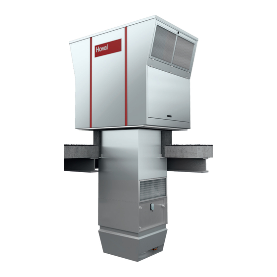
RH | RC | RHC | R RoofVent ® 1 Use 1.1 Intended use RoofVent units are supply and extract air handling units for use in tall, single-floor ® halls. They have the following functions: ■ Fresh air supply ■ Extract air removal ■... -
Page 4: Safety
RH | RC | RHC | R RoofVent ® Safety 2 Safety 2.1 Symbols Caution This symbol warns against risk of injury. Please heed all instructions desig- nated by this symbol to prevent injuries and/or death. Attention This symbol warns against property damage. Please heed the respective instructions to prevent risk of damage to the unit and its functions. -
Page 5: Construction And Operation
RH | RC | RHC | R RoofVent ® Construction and operation 3 Construction and operation 3.1 Construction RoofVent units consist of the following components: ® ■ Roof unit with energy recovery ■ Below-roof unit The components are bolted together and can be dismantled. The connections of the coil are located under the extract air grille as standard. - Page 6 RH | RC | RHC | R RoofVent ® Construction and operation Condensate separator (RoofVent RC, RHC only) ® Cooling coil (RoofVent RC, RHC only) ® Heating coil (RoofVent RH, RHC only) ® Access panel, coil Access panel, connection box Supply air fans Supply air access door Control block...
-
Page 7: Function Diagram
RH | RC | RHC | R RoofVent ® Construction and operation 3.3 Function diagram Fresh air Temperature sensor air outlet ER (optional) Fresh air filter with differential pressure switch Extract air filter with differential pressure switch Temperature sensor air inlet ER (optional) Supply air fans with flow rate monitoring Bypass damper with actuator Extract air... -
Page 8: Operating Modes
RH | RC | RHC | R RoofVent ® Construction and operation 3.4 Operating modes The units have the following operating modes: ■ Ventilation ■ Exhaust air ■ Ventilation (reduced) ■ Supply air ■ Air quality ■ Standby ■ Recirculation (depending on unit type) ■... - Page 9 RH | RC | RHC | R RoofVent ® Construction and operation Code Operating mode Description Recirculation Supply air fan ....0 / Speed 1 / Speed 2 Exhaust air fan ....off On/Off recirculation operation with TempTronic algorithm: During heat Energy recovery ....
-
Page 10: Unit Type Reference
RH | RC | RHC | R RoofVent ® Unit type reference 4 Unit type reference RHC - 9 B C - RX / ST . -- / V0 . D1 . LU / AF . SI / Y . KP . -- . SD / TC . EM . PH . RF / S--- Unit type RoofVent RH | RC | RHC | R... - Page 11 RH | RC | RHC | R RoofVent ® Unit type reference RHC - 9 B C - RX / ST . -- / V0 . D1 . LU / AF . SI / Y . KP . -- . SD / TC . EM . PH . RF / S--- Silencers outside without Fresh air silencer...
-
Page 12: Technical Data
RH | RC | RHC | R RoofVent ® Technical data 5 Technical data 5.1 Application limits Extract air temperature max. 50 °C Extract air relative humidity max. 60 % Moisture content of extract air max. 12.5 g/kg Fresh air temperature min. -
Page 13: Flow Rate, Product Parameters
RH | RC | RHC | R RoofVent ® Technical data 5.4 Flow rate, product parameters Unit size Nominal air flow rate m³/h 5500 8000 m³/s 1.53 2.22 Floor area reached m² Specific fan power SFP W/(m³/s) Face velocity 2.69 2.98 Static efficiency of the fans Internal pressure drop of ventilation... -
Page 14: Heat Output
RH | RC | RHC | R RoofVent ® Technical data 5.5 Heat output Unit ∆p Size Type °C 30.3 19.7 16.0 28.7 1300 50.0 39.5 11.6 39.3 2150 43.2 28.8 16.4 28.7 1856 73.8 59.5 11.7 40.1 3172 91.0 76.6 10.5 46.4... -
Page 15: Cooling Capacities
RH | RC | RHC | R RoofVent ® Technical data 5.6 Cooling capacities Unit ∆p Size Type °C kg/h 24.5 34.5 19.1 15.7 4943 14.7 36.0 49.6 28.2 15.5 7105 20.0 44.2 66.6 36.4 12.5 9542 33.0 Legend: Type = Type of coil = Sensible cooling capacity = Total cooling capacity = Output for coverage of transmission sensible gains (→... - Page 16 RH | RC | RHC | R RoofVent ® Technical data 5.7 Dimensions and weights of the RoofVent ® 2380 1950 Roof unit with energy recovery Heating section Connection module Air-Injector Access panel, coil Return Access panel, connection box Flow Fig.
- Page 17 RH | RC | RHC | R RoofVent ® Technical data Unit type RH-6 RH-9 1400 1750 1040 1240 1048 1100 Connection module 1190 1440 1940 1230 1480 1980 1030 1530 1030 1530 1700 1950 2200 2700 1850 2100 2350 2850 Table 7: Dimensions of the RoofVent ®...
- Page 18 RH | RC | RHC | R RoofVent ® Technical data 5.8 Dimensions and weights of the RoofVent ® 2380 1950 Roof unit with energy recovery Air-Injector Connection module Return Access panel, coil Flow Access panel, connection box Condensate connection G1" (external) Heating/cooling section Fig.
- Page 19 RH | RC | RHC | R RoofVent ® Technical data Unit type RC-6 RC-9 1400 1750 1040 1240 1048 1100 Connection module 1190 1440 1940 1230 1480 1980 1030 1530 1030 1530 2050 2300 2550 3050 2160 2410 2660 3160 Table 10: Dimensions of the RoofVent ®...
- Page 20 RH | RC | RHC | R RoofVent ® Technical data 5.9 Dimensions and weights of the RoofVent ® 2380 1950 Roof unit with energy recovery Air-Injector Connection module Heating circuit return Access panel, coil Heating circuit flow Access panel, connection box Cooling circuit return Heating section Cooling circuit flow...
- Page 21 RH | RC | RHC | R RoofVent ® Technical data Unit type RHC-6 RHC-9 1400 1750 1040 1240 1048 1100 Connection module 1190 1440 1940 1230 1480 1980 1030 1530 1030 1530 2320 2570 2820 3320 2460 2710 2960 3460 Table 13: Dimensions of the RoofVent ®...
-
Page 22: Dimensions And Weights Of The Roofvent ® R
RH | RC | RHC | R RoofVent ® Technical data 5.10 Dimensions and weights of the RoofVent ® 2380 1950 Roof unit with energy recovery Access panel, connection box Connection module Air-Injector Fig. 9: Dimensional drawing for RoofVent R (dimensions in mm) ®... - Page 23 RH | RC | RHC | R RoofVent ® Technical data Unit type 1400 1750 1040 1240 1048 1100 Connection module 1190 1440 1940 1230 1480 1980 1030 1530 1030 1530 1430 1680 1930 2430 1550 1800 2050 2550 Table 17: Dimensions of the RoofVent ®...
-
Page 24: Options
RH | RC | RHC | R RoofVent ® Options 6 Options 6.1 Oil-proof design RoofVent units in oil-proof design are suitable for use in applications with oil-satu- ® rated extract air. The maximum oil load in the extract air is 10 mg/m³ air. Attention Danger of damaging the units due to supply air containing oil. -
Page 25: Connection Module
RH | RC | RHC | R RoofVent ® Options 6.5 Connection module The connection module is available in 4 lengths for adapting the RoofVent unit to ® local conditions. 6.6 Design with 2 Air-Injectors A supply air duct can be connected to the RoofVent unit for distributing the supply ®... -
Page 26: Fresh Air Silencer
RH | RC | RHC | R RoofVent ® Options 6.9 Fresh air silencer The fresh air silencer reduces noise emissions from RoofVent units on the fresh ® air side. It consists of an aluminium casing with a bird screen and acoustic insula- tion lining and is configured as an add-on part for the roof unit which can be folded downwards. -
Page 27: Supply Air And Extract Air Silencers
RH | RC | RHC | R RoofVent ® Options 6.11 Supply air and extract air silencers Supply air and extract air silencers reduce the noise from RoofVent units within ® the room. The supply air silencer is designed as a separated component and is installed above the Air-Injector. -
Page 28: Socket
RH | RC | RHC | R RoofVent ® Options 6.15 Socket For maintenance work, a socket (1-phase, 230 V AC, 50 Hz) can be installed in the roof unit, next to the control block. 6.16 Energy monitoring Energy monitoring makes it possible to display the energy saved by heat and cool recovery. -
Page 29: Transport And Installation
RH | RC | RHC | R RoofVent ® Transport and installation 7 Transport and installation Caution Risk of injury from incorrect handling. Transport, assembly and installation work may only be performed by specialists. Observe safety and accident prevention regulations. 7.1 Delivery ■... - Page 30 RH | RC | RHC | R RoofVent ® Transport and installation ■ Electrical diagram and 2 keys for the access doors (behind the supply air access door) ■ Fresh air temperature sensor and room air temperature sensor (in the zone control panel) Options The following optional components are supplied separately:...
-
Page 31: Requirements For The Installation Site
RH | RC | RHC | R RoofVent ® Transport and installation 7.2 Requirements for the installation site ■ Make sure that the roof has sufficient load-bearing capacity and that the roof frames correspond to the specifications in the design handbook. ■... -
Page 32: Installation
RH | RC | RHC | R RoofVent ® Transport and installation 7.3 Installation Caution Risk of injury caused by falling load and improper handling. During installa- tion: – Wear protective equipment (fall protection, safety helmet, safety shoes). – Do not stand under suspended loads. – Use cranes or forklifts with sufficient load-bearing capacity. - Page 33 RH | RC | RHC | R RoofVent ® Transport and installation Assembling the below-roof unit The below-roof unit must only be assembled at the building site if it must be deliv- ered in multiple parts due to the unit version. Proceed as follows: ■...
- Page 34 RH | RC | RHC | R RoofVent ® Transport and installation Installing fresh air and exhaust air silencers Fresh air and exhaust air silencers (optional) are supplied separately and must be installed on the roof unit at the building site. The installation material is provided. Proceed as follows: ■...
- Page 35 RH | RC | RHC | R RoofVent ® Transport and installation Installing the below-roof unit ■ Apply sealing compound to the roof frame. ■ Release the cable fastening on the below-roof unit frame and carefully insert the cable into the unit. Caution Danger of damaging the unit: Dropping the cable may damage the heating or cooling coil.
- Page 36 RH | RC | RHC | R RoofVent ® Transport and installation Installing the roof unit ■ Remove the cover caps on the unit roof. ■ Screw in the transport eyes and attach the lifting gear. – Heed the minimum length of the lifting ropes (see Fig. 26). ■...
- Page 37 RH | RC | RHC | R RoofVent ® Transport and installation ■ Install the extract air filter and attach the elements using the filter brackets. Caution Danger of hazardous emissions from damaging the filters: – Only hold the compact filters on the black filter frame; never touch the white filter medium.
-
Page 38: Connecting Air Ducts And Air-Injectors
RH | RC | RHC | R RoofVent ® Transport and installation 7.4 Connecting air ducts and Air-Injectors Attention Danger of damaging the units. The unit must not be subjected to the weight of the ducts. Suspend the ducts from the ceiling or support them on the floor. -
Page 39: Hydraulic Installation
RH | RC | RHC | R RoofVent ® Transport and installation 7.5 Hydraulic installation ■ Connect the heating or cooling coil in accordance with the hydraulic diagram. ■ Depending on local conditions, check whether compensators for linear expan- sion are required for the supply and return lines and/or articulated connections are required for the units. -
Page 40: Condensate Connection
RH | RC | RHC | R RoofVent ® Transport and installation Pressure drop in kPa Pressure drop in kPa 1.6 1.8 1.2 1.4 1.8 2.0 1000 2000 3000 4000 5000 6000 7000 8000 9000 10000 11000 1.6 1.8 Water flow rate in l/h 1.2 1.4 1.8 2.0 Diagram 1: Default values for the balancing valves... - Page 41 RH | RC | RHC | R RoofVent ® Transport and installation Condensate pump (option) ■ Remove the transport locking device from the condensate pump. ■ Install the condensate pump directly under the condensate drain connection; the supplied container is prepared for installation on the Air-Injector. ■...
-
Page 42: Electrical Installation
RH | RC | RHC | R RoofVent ® Transport and installation 7.7 Electrical installation Caution Danger from electric current. The electrical installation is to be carried out only by a qualified electrician. Please note the following: ■ Observe all relevant regulations (e.g. EN 60204-1). ■... -
Page 43: Operation
RH | RC | RHC | R RoofVent ® Operation 8 Operation 8.1 Initial commissioning Caution Risk of damage to property as a result of performing initial commissioning on your own authority. Initial commissioning must be performed by the manufacturer’s customer service technicians . Preparing for initial commissioning: Checklist: ■... -
Page 44: Maintenance And Repair
RH | RC | RHC | R RoofVent ® Maintenance and repair 9 Maintenance and repair Caution Risk of injury from incorrect work. Maintenance work must be carried out by trained personnel. 9.1 Safety Before performing any work on the unit: ■... -
Page 45: Maintenance
Changing the fresh air and extract air When the filter alarm is displayed, at filter least annually Comprehensively checking function; Annually by Hoval customer service cleaning and possibly repairing the unit Filter table The following replacement filters are required: Design... - Page 46 RH | RC | RHC | R RoofVent ® Maintenance and repair Changing the filter Caution Danger of hazardous emissions from damaged filters: – Only hold the filters on the black filter frame; never touch the white filter medium. – Replace damaged filter elements immediately. Caution Crushing hazard from closing dampers.
-
Page 47: Repair
RH | RC | RHC | R RoofVent ® Dismantling 9.3 Repair If repairs are necessary, contact the manufacturer’s customer service department. 10 Dismantling Caution Risk of injury caused by falling load and improper handling. – Wear protective equipment (fall protection, safety helmet, safety shoes). –... - Page 48 RoofVent Operating Instructions ® Part. no. 4 214 745 International Hoval Aktiengesellschaft Austrasse 70 9490 Vaduz, Liechtenstein Tel. +423 399 24 00 info.klimatechnik@hoval.com www.hoval.com United Kingdom Hoval Ltd. Northgate, Newark Nottinghamshire NG24 1JN Tel. 01636 672711 heatrecovery@hoval.co.uk www.hoval.co.uk Art.No. 4 214 745-en-04 / Page 48...
Need help?
Do you have a question about the RoofVent RH Series and is the answer not in the manual?
Questions and answers