
Related Manuals for I-Panda I-P-SMART2-40A

Summary of Contents for I-Panda I-P-SMART2-40A
- Page 1 Shenzhen I-Panda New Energy Technology & Science Co., Ltd. I-P-SMART2-40A/50A/60A Manual...
-
Page 2: Table Of Contents
Contents 1 Notes on this Manual ................2 2 Safety Instructions................. 2 3 Unpacking....................5 4 Assembly....................6 5 MPPT controller Connection..............7 6 Meaning of LED/LCD and function key..........10 7 Parameter Setting................12 8 MPPT and PC Connection ............... 13 9 Technical Parameter................18 10 Maintenance and Cleaning............ -
Page 3: Notes On This Manual
Notes on this Manual This manual describes how to install and service MPPT solar charge controller. 1.1 Validity This manual applies to the whole MPPT solar charge controller models produce by our company: 1.2 Target Group This manual is intended for the installer and the operator. 1.3 All manuals for the device and installed components must be stored in the immediate vicinity of the charge controller and must be accessible at all times. -
Page 4: Safety Instructions
Safety Instructions 2.1 General Safety Instructions Warning! Due to high input working voltage, please be cautious, otherwise it is danger to life. • All work on the charge controller must only be carried out by an electrically skilled person. •The appliance is not to be used by children or persons with reduced physical sensory or mental capabilities, or lack of experience and knowledge, unless they have been given supervision or instruction. - Page 5 ● Please use components and parts recommended or sold by I-Panda New Energy. Otherwise may result in a risk of fire, electric shock, or injury to person.
-
Page 6: Unpacking
insulating tool to operate the device. ● Keep away from flammable, explosive materials to avoid fire disaster. ● The installation place should be away from humid or corrosive substance. ● To reduce the chance of short-circuits, authorized service personnel must use insulated tools when installing or working with this equipment. -
Page 7: Assembly
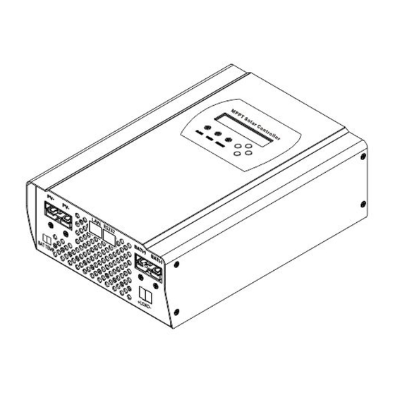
If there is any part missing, please contact your dealer. 3.2 Check for Transport Damage Check the charge controller for visible external damage, such as cracks in the enclosure. Contact your dealer if you find any damage. 3.3 Identifying the Charge Controller You can identify the charge controller by the type label. -
Page 8: Mppt Controller Connection
• The charge controller must be easy to remove from the mounting location at any time. • The ambient temperature should be between -20 °C and +60 °C to guarantee optimal operation. • Do not expose the charge controller to direct sunlight to avoid power losses due to overheating. - Page 9 5.2 Connections of the PV power system 5.2.1 PV String Solar charge controller device can be connected in series into 1-strings PV modules. Please select PV modules with excellent function and reliable quality. Open-circuit voltage of module arrays connected in series should be less than Max. DC input Voltage (150V);...
- Page 10 eagle . The details please check the illustrate . The charging voltage of battery type Bulk Voltage Floating Voltage Battery Type 14.2V 28.6V 57.2V 13.2V 26.4V 52.80V Vented 14.2V 28.6V 57.2V 13.4V 26.8V 53.60V Sealed 14.2V 28.6V 57.2V 13.7V 27.40V 54.80V NiCd 14.2V...
- Page 11 Model I-P-Smart2- I-P-Smart2- I-P-Smart2- Cable (Cu) ≥4mm ≥4mm ≥4mm Micro-Breaker 63 A 63 A Micro-breaker should be installed between DC output and battery. Kindly check the following picture ( we do not provide built-out breaker ): 5.2.5 MPPT controller work step Cation : Please follow the steps ,or the machine will be easy to broke .
-
Page 12: Meaning Of Led/Lcd And Function Key
5.2.6 The step of turn off machine Cation : Please follow the steps ,or the machine will be easy to broke . Step 1 : Turn off the PV input breaker ,make sure PV and controller disconnect . Step 2: Turn off the battery breaker , the machine will be complete off . Warning:... - Page 13 reduction ) ENTER ------------------ ENTER key ( For enter in ) ESC ------------------- ESC Key ( For exit and save data ) 6.2 Charge Mode This controller have 3 mode :Constant charging stage ( CC Mode ) , Constant voltage charging stage ( CV Mode ) , Floating charge Stage ( FC Mode ) : In CC Mode ,the blue light will flash for every second .
- Page 14 Bat Type Sel Nicd Setting Sealed User Def Special battery ,just need to set User Bat Set Main charging voltage and Bulk Volt Set float charging voltage .Please based on one battery . Float Could set any data under rated Max Chg Cur Set number Date Set...
-
Page 15: Parameter Setting
7、 Parameter Setting When controller connect with battery and it is in on state ,the controller will show the information of Work Status . 7.1 Could be set parameter of MPPT Please check the details under Setting Interface 7.2 The steps of setting Press ESC into main menu ---->... - Page 16 overview : Get into main interface as following Com Setting ( Com) :Get into set the connection of Solar Eagle and PC . Setting:Get into battery type set and load control set interface...
- Page 17 Data:MPPT working status Event Log :MPPT working status per day Login :Some parameters set need administrator’s pass word . 8.2 Then connection of MPPT and Solar Eagle . Could connect trough RS 232 ( COM ) or ( TCP/IP) 8.2.1 Connect through RS232 ( COM ) 1)Customer’s PC have RS232 connector , check the following picture Step 1 : Please install Solar Eagle ,details please kindly check install steps .
- Page 18 Step 2 : Installed and connected controller ,and make sure controller under on state (after controller connect battery ,the controller will automatic start ) Step 3:Connect PC and controller with RS232 ,make sure they had been connect ,PC will notice com ,at this time the PC will chose COM1 : Step 4:Open Solar Eagle ( WIN 7 ,...
- Page 19 Step 1 : Please install Solar Eagle ,details please kindly check install steps . Step 2 : Installed and connected controller ,and make sure controller under on state (after controller connect battery ,the controller will automatic start ) Step 3: Connect PC and controller through RJ45 . Step 4: First way :Based on PC GATED ADDRESS and IP ADDRESS to set the controller’s PC GATED ADDRESS and IP ADDRESS .
- Page 20 If have some special parameters need to be change , please purchase pass from our company : Step 1;Contact us to have password Step 2:Login Step 3:Change parameters 9、Parameters Model:I-P-SMART2-40A/50A/60A -series Charge Mode Maximum Power Point Tracking Method 3 stages: fast charge(MPPT),constant voltage, floating charge System Type...
- Page 21 PV Modules 12V/24V/48Vsyste ≥99% Utilization Rate Input Characteristics 12V system DC18V~DC150V MPPT Working 24V system DC34~DC150V Voltage and Range 48V system DC65~DC150V 12V system DC16V Low Voltage Input 24V system DC30V Protection Point 48V system DC60V 12V system DC22V Low Voltage Input 24V system DC34V Recovery Point...
- Page 22 Ripples(peak) system Output Voltage 12V/24V/48V ≤±1.5% Stability Precision system Charge voltage 12V/24V/48V 200mV Peak-Peak Ripple System Charger voltage 12V/24V/48V ≤±1.5% accuracy System Discharge characteristic Setting Control Controller or LAN Max discharge 12V/24V/48V current System Discharge 12V/24V/48V fuse 30A*2 protection System 12V/24V/48V Double-time control On in morning ,off in morning / On in night ,off in night...
-
Page 23: Maintenance And Cleaning
slowly or stop; when controller stop working, fan also stop ran. World brand raw materials. Compliance with EU Components standards. All rated temperature of electrolytic capacitors not less than 105℃ Smell No peculiar smell and toxic substances. Environment Protection Meet the 2002/95/EC,no cadmium hydride and fluoride Physical Measurement DxWxH (mm) 270*185*90... -
Page 24: Storage And Waste Disposal
Location of Thermal Fuses 10.2 Cleaning the Cooling Fin Clean the Fan air vents and internal cooling fin regularly by using the dry or small wet cloth to wipe. Attention: • Liquid detergent or corrosive solvent cleaning are forbidden. • Liquid is not allowed to down in the device. •... -
Page 25: 12. Recovery Processing And Warranty
12. Recovery Processing and Warranty Recovery Processing 12.1 When the controller abnormal, please check the following question and contact the customer service representative. 11.1.1 Controller failure mode: Please check the fault tips in the failure mode, and then proceed to the appropriate troubleshooting;...
Need help?
Do you have a question about the I-P-SMART2-40A and is the answer not in the manual?
Questions and answers