Table of Contents
Advertisement
Advertisement
Table of Contents

Subscribe to Our Youtube Channel
Summary of Contents for Frontier TD2427
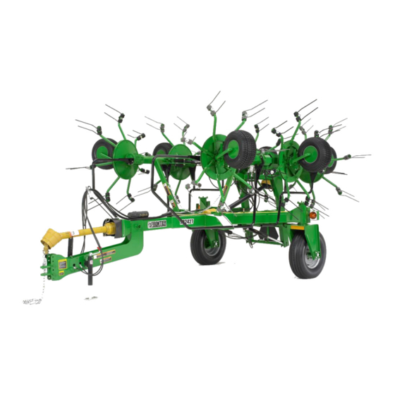
- Page 1 O P E R A T O R ' S M A N U A L TEDDER TD2427 5PQ990107 (07/20/12)
- Page 2 To the Owner; Thank-You for choosing a quality product from Frontier Equipment. We strive to give you the best equipment and the best level of service of any company. With a little care and maintenance this machine will do your work for you for many years.
-
Page 3: Table Of Contents
TABLE OF CONTENTS Introduction …………………………………………………………………….…… 2 Intended Use ……………….………………………………….…… 2 Serial Number ………………………………..………………….… 2 Specifications …………………………………………………….… 2 Safety …………………………………………………………………….………….. 3 Power Source Safety ……………………………………………… 3 Driveline Safety ……………..……………………………………… 4 Safety Decals and Reflectors ………….………………………… 5 Hitching ………………………………………………………………………………. 6 Attaching to the Tractor …………………………………………… 6 Transporting …………………………………………………………………………... -
Page 4: Introduction
INTRODUCTION Intended Use Frontier Tedders are designed for evenly distributing and drying hay crops only. Frontier will not cover under warranty a tedder that has been used outside of these crops. Serial Number The tedder’s serial number can be found on the right side tongue directly under the driveline. -
Page 5: Safety
Be constantly aware of the ends of the machine to avoid collision with other objects. When transporting the machine on public roads use the proper reflectors, lights, and slow moving vehicle signs required by local government agencies. Frontier will not be liable for any traffic violations. -
Page 6: Driveline Safety
SAFETY Stay Clear of Rotating Drivelines TS1644-UN-22AUG95 H96219-UN-29APR10 Entanglement in rotating driveline can cause serious injury or death. Keep tractor master shield and driveline shields in place at all times. Make sure rotating shields turn freely. Wear close fitting clothing. Stop the engine and be sure that PTO driveline is stopped before making adjustments, connections, or cleaning out PTO driven equipment. -
Page 7: Safety Decals And Reflectors
SAFETY Safety Decals and Reflectors Safety decals and reflectors are for the safety of yourself and others, and must be heeded at all times. If any decals are missing, faded, or damaged in any way, please contact your dealer for replacements immediately. -
Page 8: Hitching
PTO stand down against the tongue to avoid damage to the PTO shaft shielding. The TD2427 is equipped with hydraulic cylinders to fold the machine for transport. The hoses should be connected to a double acting valve at the rear of the tractor. The slotted holes on the side of the tongue (Figure 1) are storage holes for the hoses Connect the wiring plug from the tedder into the female plug end on the tractor. -
Page 9: Transporting
Adhere the suggestions for field transport listed above. ALWAYS FOLLOW LOCAL TRAFFIC LAWS IN REGARDS TO THE TRANSPORTING OF FARM EQUIPMENT. FRONTIER WILL NOT BE HELD LIABLE FOR FINES INCURRED DUE TO TRAFFIC VIOLATIONS. Do not exceed 20 MPH on any public road. Excessive speeds combined with common road ob- structions can cause failures. -
Page 10: Field Set-Up
FIELD SET UP To lower the tedder into tedding position engage the hydraulics for the tilt cylinder first to raise the wings off of the chassis then engage the main hydraulics to unfold the wings. Be sure that nobody is around the tedder or the tractor as the wings are lowering. The tines and arms can cause serious injury to anybody that it comes into contact with. -
Page 11: Adjustments
ADJUSTMENTS Tine Pitch Adjustments Figure 8 Figure 7 The tine pitch (the angle of the tine in relation to the tine arm) can be adjust- ed by reversing the eccentric spacer washer. The spacer position in Figure 7 will give the tine a less aggressive position as shown in Figure 8. The spacer position shown in Figure 9 will give the tine a more aggressive position as shown in Figure 10. -
Page 12: Axle Adjustments
ADJUSTMENTS Axle Adjustments The angle of the axles can be adjusted to raise or lower the whole machine. This will allow you to tilt the tedder forward more and get a more aggres- sive tedding action. The tedders are set at the fac- tory to run in the less aggressive position (shown at right). -
Page 13: General Operation
GENERAL OPERATION DO NOT BEGIN OPERATION UNTIL ALL OF THE SAFETY WARNINGS HAVE BEEN READ AND UNDERSTOOD! Once all of the adjustments and initial set up instructions have been followed and the proper adjustments made, the tedder is ready to operate in the field. Connect the tedder PTO shaft to the tractor by pulling the spring collar back and sliding the shaft yoke onto the 6 splined tractor PTO shaft. -
Page 14: Lubrication And Maintenance
LUBRICATION AND MAINTENANCE NEVER PERFORM ROUTINE MAINTENANCE, REPAIRS OR INSPECTIONS ON ANY PIECE OF EQUIPMENT UNLESS THE TRACTOR IS SHUT OFF AND DISCONNECTED FROM THE MACHINE. IT IS ALWAYS BETTER TO WORK WITH ANOTHER PERSON WHEN MAINTAINING OR SERVICING A PIECE OF EQUIPMENT. ACCIDENTS CAN BE PREVENTED AND HELP CAN BE ATTAINED EASIER WHEN ANOTHER PERSON IS AVAILABLE TO HELP. -
Page 15: General Lubrication
LUBRICATION AND MAINTENANCE FILL PLUGS The rotor gearboxes are packed at the factory with Cas- trol Number NLGI #2 EP Grease. This is a grease with a high resistance to water and will not dry out or be- come caked. Check the gearboxes periodically to make sure the gears are coated with grease and add more as needed. -
Page 16: Grease Fitting Lubrication
LUBRICATION AND MAINTENANCE The wheel bearings are sealed bear- ings and should be greased periodi- cally but can be overgreased. Once per season should be adequate. The transport lock slide should be greased regularly and should be kept visibly wet with grease. The sliding shaft should be cleaned periodically to prevent buildup that would prevent it from sliding smoothly. -
Page 17: Pto Lubrication
LUBRICATION AND MAINTENANCE PTO Shaft Lubrication The radial pin clutch and the center cross in the PTO yokes should be greased every 8 hours. The plastic PTO shielding should be lubricated at all times. If the shield feels tight when it is extended and re- tracted then lubricate as necessary. -
Page 18: Wheel Bearing Maintenance
LUBRICATION AND MAINTENANCE As is the case with any piece of new equipment, periodically check for loose bolts and nuts. Paint and parts settling after the initial vibrations are common and can cause bolts or nuts to loosen. Check the following parts frequently: •... -
Page 19: Electrical
Shown below is the wiring diagram for the 7-pin connector plug and the color code used for all Frontier equipment and trailers. The drawing is shown looking at the back side of the plug insert. NOTE: this is showing the full wiring schematic for this type of plug. -
Page 20: Technical
TECHNICAL Timing the Rotors The rotor gears are set at the factory and should not need to be serviced or retimed. If something does happen that causes the gears to come out of time you can follow the steps below to retime: •... -
Page 21: Replacing The Flotation Springs
TECHNICAL Replacing the Flotation Springs The flotation springs are located inside the mounting stem of the transport wheels. (The large wheels on the chassis). These wheels are also designed to carry the weight of the chassis when the tedder is in the working mode. -
Page 22: Torque Specifications
TORQUE SPECIFICATIONS The torque chart below lists the standard torque values for all attachment hardware on the rake unless otherwise specified in this manual. Standard Torque Chart GRADE 5 BOLTS GRADE 8 BOLTS TORQUE (DRY) LUBRICATED TORQUE (DRY) LUBRICATED BOLT SIZE FT.LBS. -
Page 23: Metric Torque Chart
TORQUE SPECIFICATIONS Metric Torque Chart NEWTON METERS (NM) FOOT POUNDS (FT. LBS.) BOLT SIZE & PITCH CLASS PLATED UNPLATED PLATED UNPLATED M4 x .70 3.10 2.20 2.30 1.65 M5 x .80 6.10 5.50 4.58 4.13 M6 x 1.00 10.40 9.50 7.80 7.13 M7 x 1.00... -
Page 24: Warranty
WARRANTY Warranty coverage is provided by John Deere according to the terms of the Agricultural/Commercial & Consumer Equipment Warranty Statement. Carefully read the warranty statement on the back of your original purchase order for details on coverage and limitations of this warranty. -
Page 25: Illustrated Parts Breakdown
Illustrated Parts Breakdowns... -
Page 26: Chassis Assembly
Chassis Assembly Ref# Description Part# Ref# Description Part# PTO Shield 5PQ702333 Hose Block Kit 5PQ507294 Bolt, 1/2 x 1-1/2 5PQ000435 Plastic PTO Shield 5PQ701205 Flange Bearing 5PQ500067 Plastic Guide 5PQ702436 Drive Line 5PQ700917 Jack Handle 5PQ500010 Flange Bearing 5PQ500067 Pin & Chain 5PQ102121 Bolt, 1/2 x 1-1/2 5PQ000435... -
Page 27: Transport Axle Assembly
Transport Axle Assembly Ref# Description Part# Spring Cap 5PQ702412 Bolt, 3/8 x 1-1/4 5PQ000275 Bolt, 1/4 x 3/4 5PQ000170 Oval Taillight, Red 5PQ100139 Oval Grommet 5PQ100140 Round Taillight, Amber 5PQ507164 Light Box 5PQ702506 Bronze Bushing 5PQ702339 3.500 Ext. Ring 5PQ702409 4”... -
Page 28: Transport Lock Assembly
Transport Lock Assembly Ref# Description Part# Bolt, 3/4 x 3 5PQ000715 Lock Push Arm Assembly 5PQ702402 Bolt, 3/4 x 6-1/2 5PQ000766 Lift Carriage Assembly 5PQ702323 Locknut, 3/4 5PQ000990 Ball Joint Swivel 5PQ300044 Bronze Bushing 5PQ400311 Machinery Bushing 5PQ500197 Bolt, 1/2 x 2 5PQ000452 Lock Linkage 5PQ702399... -
Page 29: Lift Frame Assembly
Lift Frame Assembly 22 23 Ref# Description Part# Ref# Description Part# Handle 5PQ502149 Roll Pin, 1/4 x 1-3/4 5PQ500187 Front Cylinder Handle 5PQ502269 Cylinder Pin 5PQ701021 Threaded Cylinder Mount 5PQ502218 Cylinder 5PQ702358 Roll Pin, 1/4 x 1-3/4 5PQ500187 Lift Carriage Assembly 5PQ702323 Tilt Cylinder 5PQ701070... -
Page 30: Guards
Guards Ref# Description Part# Roll Pin, 1/4 x 1-3/4 5PQ500187 Machinery Bushing, 1” 5PQ001008 Cylinder Pin 5PQ701016 2x28 Cylinder 5PQ701144 Bolt, 1/4 x 1/2 5PQ000170 Flatwasher, 1/4” 5PQ001020 Rubber Pivot Cover 5PQ701189 Rubber Pivot Cover, Outer 5PQ701032 Outer Guard, Left 5PQ701056 Inner Guard, Left 5PQ702510... -
Page 31: Rotor & Tine Arm
Rotor & Tine Arm Ref# Description Part# Ref# Description Part# Spacer Plate 5PQ701006 Radius Washer 5PQ701008 Bolt, M10 x 40 5PQ002415 Black Tine, Counter Clockwise Rotation 5PQ700901 Rake Flange 5PQ702002 Grey Tine, Clockwise Rotation 5PQ700929 Hay Guard (half circle) 5PQ701185 Tine Pitch Adjustment Washer 5PQ701005 Hay Guard Kit (2 halves plus hdwr.) -
Page 32: Axle Assembly
Axle Assembly Ref# Description Part# Ref# Description Part# Spindle Adjustment Pin 5PQ701026 Spindle Washer 5PQ500206 Spindle Adjustment Handle 5PQ701025 Spindle Nut 5PQ500207 Spindle Adjustment Spring 5PQ701027 Dust Cap 5PQ500209 Machinery Bushing, 5/8” 5PQ401442 Complete Hub 5PQ500199 Roll Pin, 12mm x 60mm 5PQ702019 4-Bolt Rim 5PQ500222... -
Page 33: Gearbox Assembly
Gearbox Assembly See page 32 for exploded breakdown of gearbox See page 33 for exploded breakdown of gearbox 12 13 12 13 See page 34 for exploded breakdown of gearbox Ref# Description Part# Input Gearbox Assembly 5PQ702090 Center Hex Shaft, 25MM x 63.313 5PQ701190 Pivot Rotor Gearbox Assembly, Inner 5PQ702093... -
Page 34: Input Gearbox Assembly
Input Gearbox Assembly Ref# Description Part# M8-1.25 x 30 Hex Head Bolt 5PQ002875 Lockwasher, M8 5PQ002860 Oil Seal, 35 x 72 x 8 5PQ702034 Cap, Cantilevered 5PQ702059 Shim, Cantilevered Cap 0.1MM 5PQ702033 Shim, Cantilevered Cap 0.2MM 5PQ702032 Shim, Cantilevered Cap 0.5MM 5PQ702031 Retaining Ring, 35MM Ext. -
Page 35: Pivot Gearbox Assembly
Pivot Gearbox Assembly Ref# Description Part# Hex Head Bolt, M10 x 40 5PQ002415 Split Lock Washer, M10 5PQ002862 Bronze Bushing, 35mm x 30mm 5PQ702041 Joint Spacer 5PQ701197 Double U-Joint 5PQ701107 Locknut, 3/8 5PQ003000 Bolt, 3/8 x 2-1/4 Grade 8 5PQ000345 Roll Pin, 12mm x 60mm 5PQ702019 Rectangular Key, 10 x 8 x 20... -
Page 36: Outer Gearbox Assembly
Outer Gearbox Assembly Ref# Description Part# Hex Head Bolt, M10 x 40 5PQ002415 M10 Nord-Lock Washer 5PQ700944 Breather Plug 5PQ702070 Hex Head Bolt, M10 x 40 5PQ002415 Split Lock Washer, M10 5PQ002862 Housing, HT75B Outboard 5PQ702060 Cap, Blank 5PQ702058 M10-1.50 x 25 Hex Head Bolt 5PQ002405 Shim, 0.1mm 5PQ702030... -
Page 37: Pto Shaft Assembly S/N -800350
PTO Shaft Assembly -800350 11 12 13 CLUTCH FRONT 38 SHAFT DANGER DANGER DANGER Ref# Description Part# Ref# Description Part# Radial Pin Clutch 5PQ702258 Roll Pin, M10 x 75 5PQ702254 Retainer Ring 5PQ500048 Inner Profile 5PQ702255 Flanged Collar 5PQ500047 Screw 5PQ500058 Lock Collar 5PQ500046... -
Page 38: Pto Shaft Assembly S/N 800350
PTO Shaft Assembly 800350+ 11 12 13 CLUTCH FRONT SHAFT DANGER DANGER DANGER Ref# Description Part# Ref# Description Part# Radial Pin Clutch 5PQ702290 Roll Pin, M10 x 75 5PQ702254 Retainer Ring 5PQ500048 Inner Profile 5PQ702286 Flanged Collar 5PQ500047 Screw 5PQ500058 Lock Collar 5PQ500046 CV Cone &... -
Page 39: Hydraulics S/N - 800099
Hydraulics S/N - 800099 Ref# Description Part# Front Tilt Cylinder 5PQ701070 234” Hose Assembly 5PQ702450 Straight Fitting, 4MP-4MJ 5PQ290012 54” Hose Assembly 5PQ700905 Elbow Fitting, 6MB-4MJ 5PQ700907 2x28 Cylinder 5PQ701144 27” Hose Assembly 5PQ700904 Straight Fitting, 6MB-4MJ 5PQ700908 Hydraulic Manifold 5PQ700925 77.5”... -
Page 40: Hydraulics S/N 800099
Hydraulics S/N 800099+ From Tractor Ref# Description Part# 2x28 Cylinder 5PQ701144 Elbow Fitting, 4MJ x 6MB 5PQ700907 1/4” Hose x 54” 5PQ700905 1/4” Hose x 27” 5PQ700904 Elbow Fitting, 4MJ x 4MP 5PQ702459 Tilt Cylinder 5PQ701070 Elbow Fitting, 6MJ x 6MB 5PQ507287 Straight Fitting, 4MJ x 6MB 5PQ700908... -
Page 41: Decals
Danger Decal 5PQ903102 Important, Tedder Speed 5PQ903117 Warning Decal 5PQ903123 Red Reflective Strip 5PQ903112 Warning Decal 5PQ903106 Amber Reflective Strip 5PQ903121 Warning Decal 5PQ903124 Complete Decal Kit, TD2427 5PQ903131 Important Decal 5PQ903126 French Conversion Kit (OM/Decals) 5PQ903183 Warning Decal 5PQ903137...
Need help?
Do you have a question about the TD2427 and is the answer not in the manual?
Questions and answers