Table of Contents
Advertisement
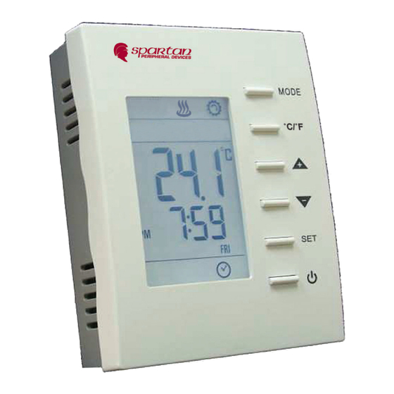
Programmable Digital Room Thermostats
Front view
Item
#
LCD
1
MODE button
2
℃/ ℉
3
button
UP & DOWN buttons
4
SET button
5
On/Off button
6
Set-point icons
7
AUTO icons
8
Flake icon
9
Hot spring icon
10
Flow icon
11
Gear icon
12
Clock
13
Sleep
14
Moon Sign
15
Outdoor icon
16
Cover screw
17
Back plate
18
Wiring terminal blocks
19
Mounting holes
20
Time
21
Schedule number
22
Day
23
Revised Date: 2017/08/24
Modulating or On/ Off Heating Control
Back view
Description
Display temperature and working status.
Access to user and engineer menu and for setting
confirmation
Toggle to change ℃/ ℉ scale unit
Increase & decrease setting or previous/next item
Setting for schedules and Time/ Date
Start/ Stop Using Heating Device
Displaying set-point temperature while it is flashing
Device is in Using
NA
Indicate working on Heating mode
NA
Indicate Heating Device currently is Open or ON
NA
NA
Indicating room is unoccupied via occupancy contact
NA
Screw to tighten back cover with front cover
Plate for mounting on electric box
Terminals for wiring
Holes for mounting on electric box
Display time
Current Schedule running or setting
Current day of Sunday ~ Saturday or Selected setting
day
TE221 Series
OPERATION MANUAL
1151-5-1-01
1
Advertisement
Table of Contents

Related Manuals for Spartan TE221 Series


Summary of Contents for Spartan TE221 Series
- Page 1 TE221 Series Programmable Digital Room Thermostats Modulating or On/ Off Heating Control OPERATION MANUAL Front view Back view Item Description Display temperature and working status. MODE button Access to user and engineer menu and for setting confirmation ℃/ ℉ Toggle to change ℃/ ℉ scale unit button UP &...
-
Page 2: Installation
Installation Mounting on electric box Separate back plate from the controller by loosing the cover screw; Align the mounting holes on the screw holes of the electric box(applicable to 65x65 or US standard box); Fix the back plate on the electric box by tightening the back plate screws. Suggest to use Philips wider “truss head” or “washer head”... -
Page 3: User Mode Operation
Operation User Mode Operation The first tier of operation includes the following settings as Figure 2. To operate: Power switch “ON” or “OFF” to start/ stop the System; After switching “ON”, press any button to start the User Mode operation. Press “MODE”... - Page 4 Fig. 2 User Mode operation sequence Revised Date: 2017/08/24...
- Page 5 Overview for the settings of Clock and Schedules � Press ℃/ ℉ or POWER button to escape any time during setting. Revised Date: 2017/08/24...
- Page 6 1. Detailed State Diagram for Clock Setting Revised Date: 2017/08/24...
- Page 7 2. Detailed State Diagram for Schedule Setting Press “Mode” button to select (day shows steadily)/ deselect (day flash). Press MODE button to Press MODE button to Press MODE button to toggle Cooling/ Heating toggle Cooling/ Heating toggle Cooling/ Heating Set points Set points Set points Revised Date: 2017/08/24...
- Page 8 Default Set Point Schedules COOL Sch. 1 6:00 6:00 6:00 6:00 6:00 6:00 6:00 26.0℃ 26.0℃ 26.0℃ 26.0℃ 26.0℃ 26.0℃ 26.0℃ 8:00 8:00 8:00 8:00 8:00 8:00 8:00 Sch. 2 29.5℃ 29.5℃ 29.5℃ 29.5℃ 29.5℃ 29.5℃ 29.5℃ Sch. 3 18:00 18:00 18:00 18:00...
- Page 9 Control Actions There are two types of heating control output: Modulating (0~10 VDC) and On/ Off (SPDT relay). Both will output simultaneously. 1. Modulating Type Heating Control: (1) Output Voltage: Valve output allow minimum adjustment (AO1 Low(E5)) from 0-2 Vdc and maximum adjustment (AO1 High(E6)) from 8 to 10 Vdc.
-
Page 10: Current Temperature
2. On/ Off Type Heating Control: (1) Control Output: SPDT relay 24Vac output allows connecting to N.O. or N.C. terminal depending on requirement. On Demand for Heat Terminal 3 will = 24Vac On/ Off differential can be set at (dIFF(E19)). Stage On/ Off Type Differential... - Page 11 c.) STOP mode means stop to use manual S.P until manually activate schedule again. And the icon ) will be NOT shown on the LCD. Revised Date: 2017/08/24...
-
Page 12: Engineer Mode Operation
Engineer Mode Operation This mode is highly suggested to be operated by trained engineers because it is related to system parameters that will affect the control results. To operate: 1. Press “Up” and “Down” buttons for over 5 seconds to enter into engineer mode; 2. - Page 13 Engineer mode menu item descriptions: °C Type °F Type Step Item Mnemonic Description Default Range Default Range Deadband 0~10.0 0~18.0 0.5 (°C/°F) Unoccupied(ESI) Cooling Set ESIC 28.0 25.0~35.0 82.0 77.0~95.0 1.0 (°C/°F) Point Unoccupied(ESI) Heating Set ESIH 15.0 10.0~22.0 59.0 50.0~72.0 1.0 (°C/°F) Point...
- Page 14 0: N.O. ESI Contact Definition 1: N.C. Present Temperature Is Getting 0: built-in from Built-In Temperature 1: remote Sensor, or Remote Temperature Sensor. Display Present Value of 0: display PV -SP- Temperature or Set-Point for 1: display SP Normal Displaying rE-C Not Used Modulating...
Need help?
Do you have a question about the TE221 Series and is the answer not in the manual?
Questions and answers