
Summary of Contents for Hawker 800 XP
- Page 1 FlightSafety international HAWKER 800 XP PILOT TRAINING MANUAL Volume 2—Aircraft Systems FlightSafety International, Inc. Marine Air Terminal, LaGuardia Airport Flushing, New York 11371 (718) 565-4100...
- Page 2 Courses for the Hawker 800 XP aircraft are taught at: FlightSafety International Greater Philadelphia/Wilmington Learning Center New Castle County Airport 155 N. DuPont Highway New Castle, DE 19720 (302) 328-7548 FlightSafety International Houston Learning Center William P . Hobby Airport...
- Page 3 F O R T R A I N I N G P U R P O S E S O N LY NOTICE The material contained in this training manual is based on information obtained from the aircraft manufacturer ’s Pilot Manuals and Maintenance Manuals.
- Page 5 CONTENTS Preface SYLLABUS Chapter 1 AIRCRAFT GENERAL Chapter 2 ELECTRICAL POWER SYSTEMS Chapter 3 LIGHTING Chapter 4 MASTER WARNING SYSTEM Chapter 5 FUEL SYSTEM Chapter 6 AUXILIARY POWER UNIT Chapter 7 POWERPLANT Chapter 8 FIRE PROTECTION Chapter 9 PNEUMATICS Chapter 10 ICE AND RAIN PROTECTION Chapter 11 AIR CONDITIONING...
-
Page 7: Table Of Contents
FlightSafety international HAWKER 800 XP PILOT TRAINING MANUAL SYLLABUS COURSE INFORMATION CONTENTS Page Course Information ......................SYL-1 Learning Center Information..................SYL-1 Description of Training Facility ...................SYL-1 Type of Aircraft ......................SYL-7 Category of Training.....................SYL-7 Duty Position ........................SYL-7 Curriculum Title ......................SYL-7 Curriculum Prerequisites ....................SYL-7 FlightSafety Training Policy..................SYL-9... - Page 8 FlightSafety international HAWKER 800 XP PILOT TRAINING MANUAL Record-Keeping Requirements ..................SYL-21 Testing for Prohibited Drugs ..................SYL-23 Aircraft Ground Training Curriculum ................SYL-24 SYSTEMS INTEGRATION....................SYL-52 CREW RESOURCE MANAGEMENT................SYL-53 FLIGHT TRAINING ......................SYL-53 FOR TRAINING PURPOSES ONLY SYL-ii...
- Page 9 FlightSafety international HAWKER 800 XP PILOT TRAINING MANUAL ILLUSTRATIONS Figure Title Page SYL-1 Houston Facility Floor Plan ................SYL-2 SYL-2 Greater Philadelphia/Wilmington Facility Floor Plan ........SYL-4 FOR TRAINING PURPOSES ONLY SYL-iii...
-
Page 11: Learning Center Information
50 different models of aircraft, using a fleet of over 150 simulators. FlightSafety operates over 38 Learning Centers, including Centers in Europe and Canada. Training for the HS 125/800 XP is conducted at two FlightSafety Learning Centers: Greater Philadelphia/Wilmington and Houston, Texas. - Page 12 FlightSafety international HAWKER 800 XP PILOT TRAINING MANUAL FlightSafety T E X A S 7525 FAUNA HOUSTON, TEXAS ATR-42 CLASSROOM COMPUTER ROOM LOUNGE BRIEFING BRIEFING ROOM ROOM PROGRAM MANAGERS STORAGE ROOM 143 ROOM 142 ROOM 141 ROOM 140 CUSTOMER SUPPORT...
- Page 13 FlightSafety international HAWKER 800 XP PILOT TRAINING MANUAL FlightSafety T E X A S 7526 WYNLEA (Back) HOUSTON, TEXAS DIRECTOR STANDARDS HAWKER OFFICE FALCON EMB-120 OFFICE WOMEN ATR 42/72 BRIEFING POWER ROOM ROOM CLOSET STORAGE CUSTOMER COMPUTER ROOM SUPPORT COFFEE...
- Page 14 INSTRUCTORS CUSTOMER MANAGER SUPPORT MANAGER ENTRANCE SIMULATORS 1. WESTWIND II 1124 2. HAWKER (SPERRY-EQUIPPED), LEVEL C ADMINISTRATION 3. HS-125/700 WITH TRs, LEVEL C SIMULATORS 4. FUTURE 5. WESTWIND 1124 VISUAL FIRST FLOOR 6. ASTRA 1125, LEVEL C 7. FOKKER 100 8.
- Page 15 FlightSafety international HAWKER 800 XP PILOT TRAINING MANUAL FlightSafety international Greater Philadelphia/ Wilmington Learning Center EXIT Wilmington, Delaware CLASSROOM CLASSROOM CLASSROOM CLASSROOM CLASSROOM CLASSROOM CLASSROOM CLASSROOM EXIT EXIT WOMEN CLASSROOM CLASSROOM GND/SIM/FLT INSTRUCTORS CLASSROOM CLASSROOM CLASSROOM CLASSROOM LOUNGE Figure SLY-2. Greater Philadelphia/Wilmington Facility Floor Plan (Second Floor)
- Page 16 FlightSafety international HAWKER 800 XP PILOT TRAINING MANUAL GREATER PHILADELPHIA HOUSTON LEARNING CENTER WILMINGTON LEARNING CENTER South Building Classroom Size in Student Classroom Size in Student Number Feet Capacity Number Feet Capacity 24 X 30 20 X 23 24 X 30...
-
Page 17: Type Of Aircraft
DUTY POSITION Pilot-in-Command (PIC) CURRICULUM TITLE HS 125/800 XP Pilot Training Course and Advanced Simulation Training Program. CURRICULUM PREREQUISITES A pilot may enroll in the initial course and complete all of the items of the practical test required for a HS-125 type rating that is authorized to be accomplished in the Level A through Level C simulator, then complete the items required in flight in a HS-125 airplane, if the pilot: 1. - Page 18 FlightSafety international HAWKER 800 XP PILOT TRAINING MANUAL Transition Training Prerequisites A pilot may enroll in the transition course and complete 100% of the practical test required for a HS-125 type rating in an approved Level C simulator, except for the preflight inspection which must be completed in either a static airplane or by using an approved pictorial means, if the pilot: 1.
-
Page 19: Flightsafety Training Policy
FlightSafety international HAWKER 800 XP PILOT TRAINING MANUAL A pilot qualifying under this subparagraph may not act as PIC of a HS-125 air- plane and will be issued a HS-125 type rating or an ATP certificate with a HS- 125 type rating as appropriate, with the limitation, “This certificate is subject to pilot-in-command limitations for the added rating,”... - Page 20 FlightSafety international HAWKER 800 XP PILOT TRAINING MANUAL DESCRIPTION OF INITIAL EQUIPMENT COURSE The HS-125 Initial Equipment Course is scheduled for fourteen days and consists of the fol- lowing programmed hours: Ground Training FlightSafety Administration Aircraft Systems 38.5 Systems Review...
-
Page 21: Description Of Transition Course
FlightSafety international HAWKER 800 XP PILOT TRAINING MANUAL DESCRIPTION OF TRANSITION COURSE The HS-125 Transition Course is scheduled for approximately fourteen days and consists of the following programmed hours: Ground Training Flight Safety Administration Aircraft Systems 38.5 Systems Review Examination System Integration §0.0... -
Page 22: Course Objectives
FAA-S-8081-5 Airline Transport Pilot and Type Rating Practical Test Standards. Successful completion of the HS-125/800 XP Pilot Training Coursewill satisfy the requirements for the following: •... - Page 23 FlightSafety international HAWKER 800 XP PILOT TRAINING MANUAL HOURS Day 3 Classroom Auxiliary Power Unit Powerplant Fire Protection Pneumatics Air Conditioning Day 4 Classroom Pressurization Hydraulic Power Systems Landing Gear and Brakes Day 5 Classroom Flight Controls Avionics Miscellaneous Ice and rain Protection Day 6 Simulator —...
- Page 24 FlightSafety international HAWKER 800 XP PILOT TRAINING MANUAL HOURS Day 9 Classroom Performance Simulator — Period No. 4 Day 10 Classroom Performance Weight and Balance Day 11 Simulator — Period No. 5 Classroom Review and Final Exam Day 12 Simulator — Period No. 6 Day 13 Simulator —...
-
Page 25: Simulator And Flight Training
FlightSafety international HAWKER 800 XP PILOT TRAINING MANUAL SIMULATOR AND FLIGHT TRAINING Pilot performance during simulator and flight training shall be graded as: Proficient (1), Normal Progress (2), Additional Training Required (3), Unsatisfactory (4), or Discussed (D). The criteria for grading shall be as follows: •... -
Page 26: Completion Standards
Pilot and Type Rating Practical Test Standards (FAA-S-8081-5). TRAINING MATERIALS, AIDS, DEVICES, AND METHODS Listed below are the training tools to implement the curriculum. Training materials: • FlightSafety’s HS-125/800 XP Pilot Training Manual • Manufacturer’s Approved Checklist • FAA-approved HS-125/800 XP Flight Manual •... - Page 27 HAWKER 800 XP PILOT TRAINING MANUAL SPZ-8000 Trainer: The SPZ-8000 Trainer permits HS-125/800 XP flight crews to become proficient in the use of the Honeywell Integrated SPZ-8000 Digital Automatic Flight Control System. Only the pilot’s side of the instrument panel is active.
-
Page 28: Supplemental Training Material
All Centers have a self-learning room that contains the following supplemental materials for the student to view. Computer-based training and interactive videodisc training: • Practical Cockpit Resource Management • Computer-based training for the HS-125/800 XP SPZ-8000 System Video Tape General Topics Areas • Flight • Windshear •... -
Page 29: Personnel Qualifications
FlightSafety international HAWKER 800 XP PILOT TRAINING MANUAL PERSONNEL QUALIFICATIONS QUALIFICATIONS—MANAGEMENT Manager The Manager is responsible for operation of the Learning Center, including planning, staffing, administration, and marketing. The manager should have a college degree or equivalent and have five years’ experience in management or sales at a decision-making level. -
Page 30: Qualifications-Pilot Ground School Instructors
FlightSafety international HAWKER 800 XP PILOT TRAINING MANUAL rectives. The Program Manager must possess an Airline Transport Pilot Certificate with a Multi-engine Rating and a type rating for the program aircraft, a Certified Flight Instructor Certificate with Instrument and Multi-engine Ratings, three years corporate pilot training ex-... -
Page 31: Miscellaneous
FlightSafety international HAWKER 800 XP PILOT TRAINING MANUAL Recurrent training for simulator instructors shall be conducted semiannually and consist of at least the following: • Director–Pilot Training or designee will observe and evaluate the instructor to determine that FlightSafety teaching standards are met. Evaluation will be documented in the Instructor Training Record and discussed with the instructor. - Page 32 FlightSafety international HAWKER 800 XP PILOT TRAINING MANUAL Instructor Training Records will consist of at least the following: • Resume of pilot at time of employment • Ground school training records • FlightSafety graduation certificate (diploma) • FlightSafety Record of Training •...
-
Page 33: Testing For Prohibited Drugs
FlightSafety international HAWKER 800 XP PILOT TRAINING MANUAL • Pilot’s current duties and the date of the pilot’s assignment to those duties • Effective dates and class of the medical certificates that the pilot holds • Date and results of each of the initial and recurrent competency tests and proficiency and route checks required by this part and the type of aircraft flown during that test or check •... -
Page 34: Aircraft Ground Training Curriculum
FlightSafety international HAWKER 800 XP PILOT TRAINING MANUAL AIRCRAFT GROUND TRAINING CURRICULUM CURRICULUM SEGMENT OUTLINE Aircraft Ground Training Curriculum Segment Objective: To provide pilots with the necessary knowledge for understanding the basic functions of aircraft systems, the use of the individual system controls, and the integration of aircraft systems with operational procedures to sufficiently pre- pare them to enter the flight training curriculum segment. -
Page 35: Systems Integration
FlightSafety international HAWKER 800 XP PILOT TRAINING MANUAL Systems Integration Modules Aircraft Preflight Walkaround SPZ-8000 Cockpit Procedures Mockup Crew Resource Management Systems Review Examination and Critique Completion Standards Systems—The pilot must demonstrate adequate knowledge of the aircraft systems by passing an open-book, written final exam with a score of 70% that is corrected to 100%. - Page 36 FlightSafety international HAWKER 800 XP PILOT TRAINING MANUAL TRAINING MODULE OUTLINES General Operational Subjects The subject of ground training, referred to as “General Operational Subjects,” includes instruction on certain operational requirements that are specific to the FAR 135 certificate holder and to the aircraft in which the training is being conducted.
- Page 37 FlightSafety international HAWKER 800 XP PILOT TRAINING MANUAL Overhead Panel Two flashlights 2. Limitation Elements Limitations Design Weights Types of Operations Maximum Altitude Maximum Crosswind Component Maneuver Limitations Maximum Occupancy Airspeed Limitations Bird Strike Protection B. Electrical Module 1. General Elements...
- Page 38 FlightSafety international HAWKER 800 XP PILOT TRAINING MANUAL START PWR Switch Circuit Breakers 1) White Background 2) Red Background AC Power Alternator Inverters Standby Inverter STBY INV Switch XE Bus Circuit Breakers 1) XE-supplied circuit breakers 2) STBY INV 3) XE Bus Supply...
- Page 39 FlightSafety international HAWKER 800 XP PILOT TRAINING MANUAL Servicing/Preflight Battery Isolate Switch Battery Switch External Battery Charge Switch 2. Operational Elements Battery Capacity Check Check Battery and Fuel Temperature Check Engine Instrument and Electrical System 3. Limitation Elements Minimum Battery Voltage...
- Page 40 FlightSafety international HAWKER 800 XP PILOT TRAINING MANUAL C. Lighting Module 1. General Elements System Description Interior Lighting Exterior Lighting Electrical Power Sources Controls and Components Aisle Lights Beacon/Pulse Cabin signs on Cabin Lights Cabin Emergency Lights Cockpit Emergency and Storm Lights...
- Page 41 FlightSafety international HAWKER 800 XP PILOT TRAINING MANUAL Controls and Components Center Annunciator Panel Roof Annunciator Panel Test Panel Indicators/Indications Master Warning Lights Engine Fire Detection Audible Warning Landing Gear Audible Warning Airbrakes Horn Warning Throttle Below 60%-70% rpm Speed Warning...
- Page 42 FlightSafety international HAWKER 800 XP PILOT TRAINING MANUAL Indicators/Indications Fuel Counter Fuel Flow Fuel Quantity Fuel Temperature REFUEL ON Light Annunciators ENG 1 LO PRESS/ENG 2 LO PRESS WING FUEL XFD/TFR AUX FUEL XFER Servicing/Preflight Fuel Quantity No. 1 and No. 2 Fuel Pumps Refuel Panel 2.
- Page 43 FlightSafety international HAWKER 800 XP PILOT TRAINING MANUAL Controls and Components APU Master Switch APU Fire Light APU Fire Extinguisher Switch APU Generator Switch Fire Warning Test Button Rear Equipment Bay Start/Run/Stop Switch Over Voltage Trip Switch Annunciators APU FAULT...
- Page 44 FlightSafety international HAWKER 800 XP PILOT TRAINING MANUAL G. Engine Module 1. General Elements System Description Major Sections Engine Systems Engine Instrumentation Engine Power Control Engine Starting Engine Synchronization Automatic Performance Reserve (APR) Airstarts Electric Power Sources (10) Power Plant Limitations...
- Page 45 FlightSafety international HAWKER 800 XP PILOT TRAINING MANUAL Indicators/Indications HP Cock Fire Light Engine Instruments APR lights Oil Press Lights Arm/Off Light Unlocked Light (10) Reverser Light Annunciators ENG 1 CMPTER ENG 2 CMPTER START PWR L-R OIL PRESS Green Operating lights 2.
- Page 46 FlightSafety international HAWKER 800 XP PILOT TRAINING MANUAL 4. Emergency/Abnormal Procedure Elements Abnormal Engine Indications Or Behavior Engine Compressor Stall Engine Computer Malfunction Engine Fire In Flight Engine Fuel Malfunction Engine Fire Warning On The Ground Engine Failure Fuel Management After One Engine Failure...
- Page 47 FlightSafety international HAWKER 800 XP PILOT TRAINING MANUAL Servicing/Preflight Preflight Extinguishers Check Discharge Discs 2. Operational Elements Discharge Extinguishers to Fight Fire 3. Emergency/Abnormal Procedure Elements APU Fire Annunciators from 1. H. 1. d. I. Pneumatics Module 1. General Elements...
- Page 48 FlightSafety international HAWKER 800 XP PILOT TRAINING MANUAL Controls and Components Cabin Fan Cabin Flood Flow Cabin Floor Cabin Temperature Control Switch Cockpit Fan Flight Deck Heat Valve Indicators/Indications Cabin Temperature Duct Temperature Annunciators REAR BAY O’HEAT 2. Emergency/Abnormal Procedure Elements...
- Page 49 FlightSafety international HAWKER 800 XP PILOT TRAINING MANUAL Annunciators CABIN ALTITUDE 2. Operational Elements Set Auto Press Controller Test CABIN ALTITUDE Annunciator Verify on the cabin triple indicator that the airplane has pressurized. 3. Limitation Elements Maximum Cabin Differential Pressure...
- Page 50 FlightSafety international HAWKER 800 XP PILOT TRAINING MANUAL Controls and Components Alternators Ammeter Reading Engine Anti-Ice Switches Ice Detect Switch Ice Protection Pitot/Vane Heat Switches Windshield Heat Switches Windscreen Alternators (10) Wing/Tail Anti-ice Time Switch Indicators/Indications TKS System Chime TKS Gage...
- Page 51 FlightSafety international HAWKER 800 XP PILOT TRAINING MANUAL 3. Emergency/Abnormal Procedure Elements Alternator Failure Double Alternator Failure Side Screen Overheat Windscreen Overheat Engine Anti-Ice Failure Annunciators from 1. L. 1. d. Pitot Heater Failure Vane Heater Failure Windscreen Damage M. Hydraulics Module 1.
- Page 52 FlightSafety international HAWKER 800 XP PILOT TRAINING MANUAL 2. Operational Elements Reset Auxiliary Hydraulic System Handle 3. Emergency/Abnormal Procedure Elements Hydraulic Low Pressure Hydraulic System Overheat Leak Scenarios Annunciators from 1. M. 1. d. Main Hydraulic Failure EMER Brake Low Pressure HYD AUX System Low N.
- Page 53 FlightSafety international HAWKER 800 XP PILOT TRAINING MANUAL 3. Limitation Elements Ground Ops Only Engine Starts Deployment on Unpaved Surfaces Full Reverse Minimum Speed 4. Emergency/Abnormal Procedure Elements Thrust Reverser Malfunctions In Flight Annunciators from 1. N. 1. c. O. Landing Gear and Brakes Module 1.
- Page 54 FlightSafety international HAWKER 800 XP PILOT TRAINING MANUAL Indicators/Indications Airbrake Indicator Gear Standby Indicators HYD LO PRESS lights Index should correspond to nosewheel position. Landing Gear Lights Normal Brake Indicator Nose Gear Mechanical Indicator Standby Gear Indicator Lights Zero Supply Gage Reading d.
- Page 55 FlightSafety international HAWKER 800 XP PILOT TRAINING MANUAL 4. Emergency/Abnormal Procedure Elements Emergency Brake Supply Failure Failure Of Landing Gear To Retract Nosewheel not Centered d. Landing Gear Three Greens Not Indicated d. Normal Brake Supply Failure Annunciators from 1. 0. 1. d.
- Page 56 FlightSafety international HAWKER 800 XP PILOT TRAINING MANUAL (18) VLV B Open lights (19) Stick Shaker (20) Stick Pusher (21) Trim Tabs (22) Wing stall vents. (23) Yaw Damper (24) Circuit Breakers Elevator Electric Trim Left and Right Stall Warning...
- Page 57 FlightSafety international HAWKER 800 XP PILOT TRAINING MANUAL 4. Emergency/Abnormal Procedure Elements Elevator Trim Runaway Stick Shaker and/or Pusher Operation Landing with Elevator Cable Failure d. Annunciators from I.P.1.d. Q. Avionics Module (See note below) 1. General Elements System Description...
- Page 58 FlightSafety international HAWKER 800 XP PILOT TRAINING MANUAL (22) Test Buttons (23) Radio Master Switches (24) Radio Emergency Switch (25) Pitot Isolation Valve (26) Remote HDG Selector (27) Rudder Bias (28) Standby Altimeter (29) Standby Horizon (30) Transfer Panels/Reversionary Mode Panels...
- Page 59 FlightSafety international HAWKER 800 XP PILOT TRAINING MANUAL d. Annunciators ALT ALERT AUX PWR L AFCS FAIL R AFCS FAIL AP OFF AP TRIM (ELV/AIL TRIM) Sync/TCS Servicing/Preflight Check Radios Transmit and Receive 2. Operational Elements Test Altitude Alert Tune and identify all nav systems and radios Apply aileron and note rudder movements in correct sense.
- Page 60 FlightSafety international HAWKER 800 XP PILOT TRAINING MANUAL R. Oxygen Module 1. General Elements System Description Oxygen Cylinder Assembly Crew Oxygen System Passenger Oxygen System Therapeutic Oxygen Outlets Portable Oxygen Smoke Set Limitations Controls and Components Check mask and regulator...
- Page 61 FlightSafety international HAWKER 800 XP PILOT TRAINING MANUAL S. Aircraft Performance Module 1. Elements Definitions Takeoff Weight to Meet Aircraft Certification Takeoff and Climb Criteria Takeoff Thrust Setting Maximum Continuous Thrust Setting Maximum Takeoff Weight Takeoff Speeds and Field Length...
- Page 62 FlightSafety international HAWKER 800 XP PILOT TRAINING MANUAL U. Flight Planning Module 1. Elements Rules of Thumb Reserve Fuel Section Charts d. Diversion Charts Other Tabulated Data SYSTEMS INTEGRATION TRAINING HOURS: HOURS Aircraft Preflight Walkaround High Altitude Training (if required)
- Page 63 FlightSafety international HAWKER 800 XP PILOT TRAINING MANUAL 3. Limitations Duration of Consciousness Without Supplemental Oxygen Effects of Prolonged Use of Supplemental Oxygen 4. Emergency Procedures Emergency Procedures for a Rapid Decompression Emergency Descent Procedures C. Cockpit Procedures Mockup 1. The CPM will be used during the simulator prebriefs to discuss the aircraft systems that will be involved during that simulator.
- Page 64 FlightSafety international HAWKER 800 XP PILOT TRAINING MANUAL FLIGHT HOURS INITIAL TRAINING Left Seat Right Seat Total Time As a Crew (Hours) (Hours) (Hours) Simulator Period No. 1 Simulator Period No. 2 Simulator Period No. 3 Simulator Period No. 4 Simulator Period No.
- Page 65 FlightSafety international HAWKER 800 XP PILOT TRAINING MANUAL INITIAL TRAINING Left Seat Right Seat Total Time Not as a Crew (Hours) (Hours) (Hours) Flight Simulator Period No. 1 Flight Simulator Period No.2 Flight Simulator Period No. 3 Flight Simulator Period No. 4 Flight Simulator Period No.
- Page 66 FlightSafety international HAWKER 800 XP PILOT TRAINING MANUAL FLIGHT TRAINING MODULE OUTLINES 1. Flight Training Curriculum Segment A. Objective: With the use of an approved flight simulator, cockpit checklist, and appropri- ate instrument approach and airport charts, the pilot will be able to accomplish the Normal and Emergency/Abnormal checklists, perform selected maneuvers and procedures, and im- plement Cockpit Resource Management techniques.
- Page 67 FlightSafety international HAWKER 800 XP PILOT TRAINING MANUAL (11) Descent and In Range (12) Before Landing (13) Close In (14) Missed Approach (15) After Landing (16) Shutdown (17) Postflight Functional Checks EFIS Ground Test—Collins Air Data Computer Check—Collins Individual Instrument Test—Collins...
- Page 68 FlightSafety international HAWKER 800 XP PILOT TRAINING MANUAL Avionics/EFIS * Display Processor Failure—Collins * Display Control Failure—Collins * EADI Failure—Collins * EHSI Failure—Collins * EFIS Fan Failure—Collins * EFIS Fan Failure—Sperry * EFIS Fan Fail Lts Illuminated Inflight—Sperry * Electronic Display Indicator Over-temperature—Sperry...
- Page 69 FlightSafety international HAWKER 800 XP PILOT TRAINING MANUAL g. Landings Normal Landing h. After Landing Parking System Procedures ~(Normal, Abnormal, Alternate) Autopilot Flight Management Guidance Systems and/or Automatic or other Approach and Landing Systems Communications Equipment Navigation Systems 4. Crew Resource Management...
- Page 70 FlightSafety international HAWKER 800 XP PILOT TRAINING MANUAL (13) Close In (14) Missed Approach (15) After Landing (16) Shutdown (17) Post Flight Functional Checks EFIS Ground Test—Collins Air Data Computer Check—Collins Individual Instrument Test—Collins Pre-Flight Check-Autopilot and Flight Guidance System (if applicable)
- Page 71 FlightSafety international HAWKER 800 XP PILOT TRAINING MANUAL (13) XS I Fail and XE Fail (14) Emergency Battery Supply (15) * Smoke Drill Engine/APU/Fuel Engine Failure Engine Relight Immediate Relight Relight Envelope Starter Assisted (Normal) Relight Windmill Relight * Engine Compressor Stall...
- Page 72 FlightSafety international HAWKER 800 XP PILOT TRAINING MANUAL d. Ice and Rain Protection Windscreen Overheat Sidescreen Overheat * Alternator Failure * Double Alternator Failure * Air Data Computer Failure 3. Flight Training Events Preparation Prestart Procedures Surface Operation Starting Taxi...
- Page 73 FlightSafety international HAWKER 800 XP PILOT TRAINING MANUAL g. Approaches Area Departure and Arrival Holding Precision ILS * Nonprecision—VOR * Nonprecision—NDB Missed Approach from a Precision Approach Missed Approach from a Nonprecision Approach h. Landings Normal Landing Landing from a Precision Instrument Approach...
- Page 74 FlightSafety international HAWKER 800 XP PILOT TRAINING MANUAL 4. Crew Resource Management *Situational Awareness and the Error Chain * Communication * Synergy and Crew Concept d. * Workload Assessment and Time Management * Briefing * Reliance on Automation g. * Decision Making and Judgement h.
- Page 75 FlightSafety international HAWKER 800 XP PILOT TRAINING MANUAL Functional Checks EFIS Ground Test—Collins Air Data Computer Check—Collins Individual Instrument Test—Collins Pre-Flight Check-Autopilot and Flight Guidance System (if applicable) Electric Pitch Trim Stall Systems Test EFIS Self Test-Sperry Air Data Computer Test—Honeywell Phase III...
- Page 76 FlightSafety international HAWKER 800 XP PILOT TRAINING MANUAL Hydraulics/Gear/Brakes Hydraulic Low Pressure Main Hydraulic Failure * Hydraulic System Overheat Normal Brake Supply Failure * Emergency Brake Supply Failure * Failure of Landing Gear to Retract * Failure of Landing Gear Position Indicator...
- Page 77 FlightSafety international HAWKER 800 XP PILOT TRAINING MANUAL Surface Operation Starting Taxi Pretakeoff Checks Takeoff Normal Takeoff Crosswind Takeoff Rejected (Aborted) Takeoff Instrument Takeoff Power Failure V (at or above V d. Climb Normal En Route Inflight Powerplant Shutdown * Inflight Powerplant Restart...
- Page 78 FlightSafety international HAWKER 800 XP PILOT TRAINING MANUAL h. Landings Normal Landing Landing from a Precision Instrument Approach Landing from a Precision Instrument Approach—One Engine Inop Landing with a Flap Malfunction Crosswind Landing Landing from a Circling Approach Rejected Landing to a Normal Missed Approach...
- Page 79 FlightSafety international HAWKER 800 XP PILOT TRAINING MANUAL 4. Crew Resource Management * Situational Awareness and the Error Chain * Communication * Synergy and Crew Concept d. * Workload Assessment and Time Management * Briefing * Reliance on Automation g. * Decision Making and Judgement h.
- Page 80 FlightSafety international HAWKER 800 XP PILOT TRAINING MANUAL Functional Checks (if needed for proficiency) EFIS Ground Test-Collins Air Data Computer Check—Collins Individual Instrument Test—Collins Pre-Flight Check-Autopilot and Flight Guidance System (if applicable) Electric Pitch Trim Stall System Test EFIS Self Test—Sperry Air Data Computer Test—Honeywell Phase III...
- Page 81 FlightSafety international HAWKER 800 XP PILOT TRAINING MANUAL Pressurization/Pneumatics Depressurization or Complete Loss of Air Supply Emergency Descent Failure to Pressurization Automatic Pressure Control Failure * Duct Overheat * Automatic Temperature Control Failure Rear Equipment Bay Overheat High Pressure Air Overheat...
- Page 82 FlightSafety international HAWKER 800 XP PILOT TRAINING MANUAL Surface Operation Starting Taxi Pretakeoff Checks Takeoff Normal Takeoff Normal Noise Abatement Takeoff Normal Takeoff (in ice, and use of Engine Anti-ice and TKS) Crosswind Takeoff Rejected (Aborted) Takeoff Instrument Takeoff Power Failure V (at or above V d.
- Page 83 FlightSafety international HAWKER 800 XP PILOT TRAINING MANUAL h. Landings * Normal Landing Landing from a Precision Instrument Approach Landing from a Precision Instrument Approach—One Engine Inop Landing with a Flap Malfunction * Crosswind Landing Maneuver to Landing with a Powerplant Failure...
- Page 84 FlightSafety international HAWKER 800 XP PILOT TRAINING MANUAL System Procedures (Emergency) * Aircraft Fires * Smoke Control Powerplant Malfunctions * Electrical Systems * Hydraulic Systems * Pneumatic Systems * Flight Control Systems Malfunction * Landing Gear and Flap System Malfunction 4.
- Page 85 FlightSafety international HAWKER 800 XP PILOT TRAINING MANUAL (14) Missed Approach (15) After Landing (16) * Shutdown (17) * Post Flight Functional Checks * EFIS Ground Test—Collins * Air Data Computer Check—Collins * Individual Instrument Test—Collins * Pre-Flight Check-Autopilot and Flight Guidance System (if applicable)
- Page 86 FlightSafety international HAWKER 800 XP PILOT TRAINING MANUAL Engine/APU/Fuel * Engine Fire Warning Light * Engine Fire Warning on the Ground * Engine Failure * Engine Relight * Immediate Relight * Relight Envelope * Starter Assisted (Normal) Relight * Windmill Relight...
- Page 87 FlightSafety international HAWKER 800 XP PILOT TRAINING MANUAL d. Hydraulics/Gear/Brakes * Hydraulic Low Pressure * Main Hydraulic Failure * Hydraulic System Overheat * Normal Brake Supply Failure * Emergency Brake Supply Failure * Failure of Landing Gear to Retract * Nosewheel not Centered...
- Page 88 FlightSafety international HAWKER 800 XP PILOT TRAINING MANUAL 3. Flight Training Events (events may be combined as necessary) Preparation * Prestart Procedures Surface Operation * Starting * Taxi * Pretakeoff Checks Takeoff Normal Takeoff Crosswind Takeoff Rejected (Aborted) Takeoff Instrument Takeoff...
- Page 89 FlightSafety international HAWKER 800 XP PILOT TRAINING MANUAL h. Landings * Normal Landing Landing from a Precision Instrument Approach * Crosswind Landing * Maneuver to Landing with a Powerplant Failure from a Visual Approach * Landing from a Circling Approach...
- Page 90 FlightSafety international HAWKER 800 XP PILOT TRAINING MANUAL System Procedures (Emergency) * Aircraft Fires * Smoke Control Powerplant Malfunctions * Electrical Systems * Hydraulic Systems * Pneumatic Systems * Flight Control Systems Malfunction * Landing Gear and Flap System Malfunction 4.
- Page 91 FlightSafety international HAWKER 800 XP PILOT TRAINING MANUAL (14) Missed Approach (15) After Landing (16) Shutdown (17) Post Flight Functional Checks EFIS Ground Test—Collins Air Data Computer Check—Collins Individual Instrument Test—Collins Pre-Flight Check—Autopilot and Flight Guidance System (if applicable) Electric Pitch Trim Stall System Test EFIS Self Test—Sperry...
- Page 92 FlightSafety international HAWKER 800 XP PILOT TRAINING MANUAL Engine/APU/Fuel * Engine Fire Warning Light * Engine Fire Warning on the Ground * Engine Failure * Engine Relight * Immediate Relight * Relight Envelope * Starter Assisted (Normal) Relight * Windmill Relight...
- Page 93 FlightSafety international HAWKER 800 XP PILOT TRAINING MANUAL d. Hydraulics/Gear/Brakes * Hydraulic Low Pressure * Main Hydraulic Failure * Hydraulic System Overheat * Normal Brake Supply Failure * Emergency Brake Supply Failure * Failure of Landing Gear to Retract * Nosewheel not Centered...
- Page 94 FlightSafety international HAWKER 800 XP PILOT TRAINING MANUAL h. Ice and Rain Protection * Windscreen Overheat * Sidescreen Overheat * Alternator Failure * Double Alternator Failure * Air Data Computer Failure 3. Flight Training Events Preparation * Prestart Procedures Surface Operation...
- Page 95 FlightSafety international HAWKER 800 XP PILOT TRAINING MANUAL g. Approaches Area Departure and Arrival Navigation Equipment and Assigned Radials * Holding * Visual Approach—One Engine Inoperative Precision ILS Precision ILS with an Engine Out Nonprecision—VOR Nonprecision—NDB * Nonprecision with an Engine Out...
- Page 96 FlightSafety international HAWKER 800 XP PILOT TRAINING MANUAL Hydraulic Flight Controls Anti-icing and Deicing Autopilot Flight Management Guidance Systems and/or Automatic or other Approach and Landing Systems (10) Stall Warning Devices (11) Airborne Weather Radar (12) Flight Instrument System Malfunction...
- Page 97 FlightSafety international HAWKER 800 XP PILOT TRAINING MANUAL Interior Cabin Before Start-External, APU, or Battery Starting Engines-External, APU, or Battery After Start Taxi Before Takeoff Line Up (10) Immediate Return/Traffic Pattern Checklist (11) After Takeoff and Climb (12) Cruise (13)
- Page 98 FlightSafety international HAWKER 800 XP PILOT TRAINING MANUAL 2. Abnormal/Emergency Procedures Engine/APU/Fuel Engine Failure 3. Flight Training Events Preparation Visual Inspection Takeoff Normal Takeoff Crosswind Takeoff Instrument Takeoff Power Failure V (at or above V Approaches Precision ILS * Nonprecision Approach—VOR * Nonprecision Approach—NDB...
- Page 99 FlightSafety international HAWKER 800 XP PILOT TRAINING MANUAL Note Each LOFT will include any two (2) of the eight (8) legs listed in a) through h) se- lected by the instructor. The first leg will include ONLY normal procedures. The sec- ond leg may include emergency procedures.
- Page 100 FlightSafety international HAWKER 800 XP PILOT TRAINING MANUAL 6. IFR Approaches (During Final Approach) Nonprecision Approach CDI ..............±1/2 Scale Deflection RMI ................±5° Deviation Bearing Pointer ..............±5° Deviation MDA ................+50, –0 Feet Airspeed ................+5, –0 KIAS Precision Approach Glide Slope ............±1/4 Scale Deflection Localizer ............±1/4 Scale Deflection...
- Page 101 FlightSafety international HAWKER 800 XP PILOT TRAINING MANUAL CHAPTER 1 AIRCRAFT GENERAL CONTENTS Page INTRODUCTION ........................1-1 GENERAL..........................1-1 Fuselage ........................... 1-5 Wing..........................1-15 Empennage........................1-16 AIRPLANE SYSTEMS ......................1-16 General........................... 1-16 Electrical Power Systems....................1-16 Lighting.......................... 1-16 Master Warning System....................1-17 Fuel System........................
- Page 102 FlightSafety international HAWKER 800 XP PILOT TRAINING MANUAL Pitot-Static System......................1-19 Avionics ......................... 1-19 Oxygen System ......................1-19 FOR TRAINING PURPOSES ONLY 1-ii...
- Page 103 FlightSafety international HAWKER 800 XP PILOT TRAINING MANUAL ILLUSTRATIONS Figure Title Page Airplane Dimensions....................1-3 Danger Zones ......................1-4 Minimum Turning Radius ..................1-4 Fuselage Sections ..................... 1-5 Nose Section......................1-5 Cockpit Layout (Typical) ..................1-6 Flight Compartment (Typical)..................1-8 Pilot’s Seat........................ 1-7 Vestibule Arrangement...................
-
Page 105: Introduction
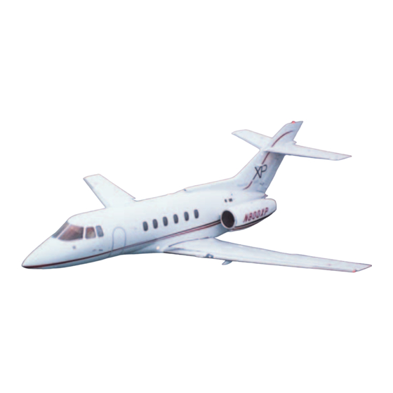
GENERAL First Officer. A third crew member may be car- ried to carry out in-flight attendants duties. The The Hawker 800 XP is a twin turbofan engined, standard layout is an eight-seat executive con- low wing monoplane aircraft, certificated for figuration. - Page 106 FlightSafety international HAWKER 800 XP PILOT TRAINING MANUAL Digital avionic systems are installed for com- A fluid anti-icing system is installed along munication, navigation, auto flight control the leading edge of the wings and horizontal and flight management systems. A five-tube stabilizer.
- Page 107 FlightSafety international HAWKER 800 XP PILOT TRAINING MANUAL 9 FT 2 IN. (2.79 M) TRACK 51 FT 4.5 IN. (15.66 M) WING SPAN 51 FT 1.64 IN. (15.59 M) OVERALL LENGTH 20 FT (6.10 M) TAIL SPAN 17 FT 5 IN.
- Page 108 FlightSafety international HAWKER 800 XP PILOT TRAINING MANUAL FULL THROTTLE: VELOCITY FALLS BELOW 15 MPH LEGEND AREA TO BE CLEARED PRIOR TO ENGINE START. FULL THROTTLE: AREA TO BE CLEARED IF TAKEOFF TEMPERATURE BELOW 30° C POWER IS TO BE USED.
-
Page 109: Fuselage
FlightSafety international HAWKER 800 XP PILOT TRAINING MANUAL FUSELAGE General The fuselage sections are the nose, center, and rear. These sections are further subdivided for dis- cussion into the nose equipment bay, the cockpit, vestibule, passenger compartment, and the rear equipment bay. - Page 110 FlightSafety international HAWKER 800 XP PILOT TRAINING MANUAL Figure 1-6. Cockpit Layout (Typical) FOR TRAINING PURPOSES ONLY...
- Page 111 FlightSafety international HAWKER 800 XP PILOT TRAINING MANUAL Cockpit thigh pad is relaxed, the pad returns to its pre- set condition. The general layout of the cockpit is shown in The recline control handle is pulled upward to Figure 1-6, and a typical flight compartment allow the seat backrest to be pushed to the rear;...
- Page 112 FlightSafety international HAWKER 800 XP PILOT TRAINING MANUAL STORM LAMP HEADSET SUB PANEL D STOWAGE HOOK STALL IDENT SUB PANEL A DIAGNOSTIC PANEL PASSENGER OXYGEN SUPPLY VALVE SILICA GEL SILICA GEL VIEWING WINDOWS VIEWING WINDOWS SPOTLAMP SWITCH HEADSET, CRASH AXE...
- Page 113 FlightSafety international HAWKER 800 XP PILOT TRAINING MANUAL The seat back cushion is adjustable for up- cabin left forward bulkhead. The main entry down and in-out lumbar support. In-out ad- door separates the forward and rear cabinets. justment is controlled by a handwheel. Rotating...
- Page 114 FlightSafety international HAWKER 800 XP PILOT TRAINING MANUAL Figure 1-9. Vestibule Arrangement FOR TRAINING PURPOSES ONLY 1-10...
-
Page 115: Main Entry Door
FlightSafety international HAWKER 800 XP PILOT TRAINING MANUAL Each forward- or aft-facing seat has an ad- The door is counterbalanced by a spring-loaded justable backrest controlled by a knob on the tensator motor and secured by external and in- outboard armrest and a retractable inboard ternal handles. -
Page 116: Escape Hatch
Following is a list of standard and optional mechanism, are connected to the master warn- ing system ENT DOOR UNLOCKED annun- emergency equipment available on the Hawker ciator. Either switch lights the annunciator 800 XP (Figure 1-13). when the door is not in a fully locked position. - Page 117 FlightSafety international HAWKER 800 XP PILOT TRAINING MANUAL Figure 1-13. Emergency Equipment Locations FOR TRAINING PURPOSES ONLY 1-13...
- Page 118 FlightSafety international HAWKER 800 XP PILOT TRAINING MANUAL Windows plies of the aft cockpit windows are connected to a silica gel container at the rear of each win- There are six windows in the cockpit, three dow (Figure 1-15). All cabin windows (see each on the pilot’s and copilot’s sides.
-
Page 119: Wing
WING On the trailing edge a double slotted flap ex- The Hawker 800 XP has a swept-back, can- tends from the wing to the fuselage. An upper tilevered, all-metal wing (Figure 1-17). The and lower air brake is positioned forward of the center wing section is contoured to fit the fuse- flap;... -
Page 120: Empennage
DC voltmeter, and an AC voltmeter are used to monitor the electrical system. LIGHTING The Hawker 800 XP has standard navigation, beacon, strobe, landing, and taxi lights. A left and right wing ice light is installed for wing ice inspection. -
Page 121: Master Warning System
APU. Overheat detection capability is also (Turbomach) manufacture power units in- provided for the rear equipment bay. Fire ex- stalled in the Hawker 800 XP. Its function is tinguishers are installed to extinguish engine to drive a DC generator to power the aircraft and APU fires. -
Page 122: Pneumatics
PNEUMATICS through the turbine. The more air that passes through the turbine, the cooler the temperature. The Hawker 800 XP uses engine bleed air to The more air that is allowed to bypass the supply pneumatically operated airplane sys- cooling turbine, the warmer the temperature. -
Page 123: Landing Gear And Brakes
HAWKER 800 XP PILOT TRAINING MANUAL LANDING GEAR AND BRAKES AVIONICS The Hawker 800 XP landing gear is hy- Standard avionics includes the EFIS 86 E or SPZ draulically actuated and fully enclosed by hy- 8000 Electronic Flight Instrument Systems. - Page 125 FlightSafety international HAWKER 800 XP PILOT TRAINING MANUAL CHAPTER 2 ELECTRICAL POWER SYSTEMS CONTENTS Page INTRODUCTION ........................2-1 GENERAL..........................2-1 DC POWER ..........................2-4 Batteries ........................... 2-4 Generators ........................2-7 APU ............................2-19 Ground Power ........................ 2-20 Distribution ........................2-21 Operation ........................
- Page 127 FlightSafety international HAWKER 800 XP PILOT TRAINING MANUAL ILLUSTRATIONS Figure Title Page Component Locations....................2-2 Circuit-Breaker Panel Locations ................2-3 Main Distribution Panel ................... 2-3 Battery Locations ..................... 2-4 DC Bus Bar Control ....................2-5 Battery Temperature Indicator.................. 2-7 Generator Cooling ....................2-8 Power Generation (Configuration No.
- Page 128 FlightSafety international HAWKER 800 XP PILOT TRAINING MANUAL 2-24 AC Power System ....................2-24 TABLES Table Title Page Electrical Component Listing................... 2-4 Inverter Controls and Locations ................2-22 FOR TRAINING PURPOSES ONLY 2-iv...
-
Page 129: Introduction
ELECTRICAL POWER SYSTEMS INTRODUCTION This chapter contains a description of the electrical power system used on the Hawker 800 XP, including information on the DC and AC systems. The DC system consists of storage, genera- tion, distribution, and monitoring DC power. The AC system consists of generation, distribu- tion, and monitoring of the constant-frequency (inverter) and the variable-frequency (alternator) AC systems. - Page 130 FlightSafety international HAWKER 800 XP PILOT TRAINING MANUAL Nos. 1 and 2 batteries, normally connected in Inverters, powered from the airplane DC system, parallel, can be manually selected to provide provide 115 volts AC for the operation of vari- DC supplies for essential services.
- Page 131 FlightSafety international HAWKER 800 XP PILOT TRAINING MANUAL DA-D PANEL (TOP) ROWS A-H DA-D PANEL (BOTTOM) ROWS J-S Figure 2-2. Circuit-Breaker Panel Locations STORM LAMP AC DISTRIBUTION GENERAL PURPOSE CBs SUBPANEL DA-D STALL INDENT TEST SOCKET AVIONICS CBs SUBPANEL DA-D...
-
Page 132: Dc Power
FlightSafety international HAWKER 800 XP PILOT TRAINING MANUAL DC POWER BATTERIES Two types of batteries may be used: • 24 VDC, 23 ampere-hour nickel-cadium • 24 VDC, 25 ampere-hour lead-acid. Located in the rear equipment bay(Figure 2-4). There are separate emergency power packs (batteries) for avionics and standby instru- ments. - Page 133 FlightSafety international HAWKER 800 XP PILOT TRAINING MANUAL Switch To ON With both generators off line and external power selected to OFF, setting the BATT switch to ON uses No. 1 battery to (refer to Fig- ure 2-9) close emergency contactors Nos. 1 and 2.
- Page 134 FlightSafety international HAWKER 800 XP PILOT TRAINING MANUAL Switch To EMERGency an internal start contactor to connect No. 1 and No. 2 batteries to a start bus bar. Bus bar Setting the switch to EMERG closes both PE remains energized, with the BATT switch...
-
Page 135: Generators
FlightSafety international HAWKER 800 XP PILOT TRAINING MANUAL No. 2 batteries to PS1 and PS2 bus bars. When the indicated rates of charge reduce to less than 5 amps, EXT BATT CHG switch should be positioned to OFF. With PE bus bar energized, the relevant BATT 1 or 2 CNTCTR annunciator illuminates when- ever the associated No. - Page 136 FlightSafety international HAWKER 800 XP PILOT TRAINING MANUAL Figure 2-7. Generator Cooling Engine Starting For either type of start the starting sequence may be terminated at any time by a second applica- The function of the engine starting circuits tion of the START PWR switch (now annunci- during the full starting sequence is described, ating “PWR ON/PUSH FOR ABORT”).
- Page 137 FlightSafety international HAWKER 800 XP PILOT TRAINING MANUAL NO. 1 NO. 2 STARTER STARTER STARTER ENG 2 ENG 1 OPERATING OPERATING START START START CONTACTOR CONTACTOR CONTACTOR GARRETT GROUND STARTER BUS POWER GEN ON CONNECTION DC BUS GEN LINE GEN LINE...
- Page 138 FlightSafety international HAWKER 800 XP PILOT TRAINING MANUAL NO. 1 NO. 2 STARTER STARTER STARTER GARRETT GEN ON DC BUS GEN LINE GEN LINE GEN 2 APU GEN GEN 1 CONTACTOR CONTACTOR FAIL SOLAR CONTACTOR FAIL NO.2 NO.1 BUS TIE...
- Page 139 FlightSafety international HAWKER 800 XP PILOT TRAINING MANUAL NO. 1 NO. 2 STARTER STARTER STARTER ENG 2 ENG 1 OPERATING OPERATING START START START CONTACTOR CONTACTOR CONTACTOR GARRETT STARTER BUS GEN ON DC BUS GEN LINE GEN LINE GEN 2...
- Page 140 FlightSafety international HAWKER 800 XP PILOT TRAINING MANUAL NO. 1 NO. 2 STARTER STARTER STARTER ENG 2 ENG 1 OPERATING OPERATING START START START CONTACTOR CONTACTOR CONTACTOR GARRETT STARTER BUS GEN ON DC BUS GEN LINE GEN LINE GEN 2...
- Page 141 FlightSafety international HAWKER 800 XP PILOT TRAINING MANUAL NO. 1 NO. 2 STARTER STARTER STARTER ENG 2 ENG 1 OPERATING OPERATING START START START CONTACTOR CONTACTOR CONTACTOR GARRETT STARTER BUS GEN ON DC BUS GEN LINE GEN LINE GEN 2...
- Page 142 FlightSafety international HAWKER 800 XP PILOT TRAINING MANUAL NO. 1 NO. 2 STARTER STARTER STARTER ENG 2 ENG 1 OPERATING OPERATING START START START CONTACTOR CONTACTOR CONTACTOR GARRETT STARTER BUS GEN ON DC BUS GEN LINE GEN LINE GEN 2...
- Page 143 FlightSafety international HAWKER 800 XP PILOT TRAINING MANUAL NO. 1 NO. 2 STARTER STARTER STARTER ENG 2 ENG 1 OPERATING OPERATING START START START CONTACTOR CONTACTOR CONTACTOR GARRETT GROUND STARTER BUS POWER GEN ON CONNECTION DC BUS GEN LINE GEN LINE...
- Page 144 FlightSafety international HAWKER 800 XP PILOT TRAINING MANUAL NO. 1 NO. 2 STARTER STARTER STARTER ENG 2 ENG 1 OPERATING OPERATING START START START CONTACTOR CONTACTOR CONTACTOR GARRETT STARTER BUS GEN ON DC BUS GEN LINE GEN LINE GEN 2...
- Page 145 FlightSafety international HAWKER 800 XP PILOT TRAINING MANUAL NO. 1 NO. 2 STARTER STARTER STARTER ENG 2 ENG 1 OPERATING OPERATING START START START CONTACTOR CONTACTOR CONTACTOR GARRETT STARTER BUS GEN ON DC BUS GEN LINE GEN LINE GEN 2...
- Page 146 FlightSafety international HAWKER 800 XP PILOT TRAINING MANUAL Any fault detection and opening of the GLC prevent the bus-tie contactor from being oper- takes the generator off line and lights the GEN ated by transients. FAIL and MWS ELECT annunciators. An at-...
-
Page 147: Apu
FlightSafety international HAWKER 800 XP PILOT TRAINING MANUAL used either to reinstate an off-line generator or If the battery charge rate cannot be read eas- to take a malfunctioning generator off line. ily on the full instrument scale, the 0-40 switch should also be pressed. -
Page 148: Ground Power
FlightSafety international HAWKER 800 XP PILOT TRAINING MANUAL varies slightly, their general operation is quite Ground power supplies are connected to the similar. airplane bus-bar system and to the starter sup- ply lines through a ground supply contactor. Contactor operation is controlled by an EXT... -
Page 149: Distribution
FlightSafety international HAWKER 800 XP PILOT TRAINING MANUAL A start inhibit facility prevents engine start- ing while the EXT BATT CHG switch located on the pilot’s roof panel is set to ON. DA-D PANEL (TOP) ROWS A-H NOTE With the BATT switch on and ground... -
Page 150: Ac Power
FlightSafety international HAWKER 800 XP PILOT TRAINING MANUAL the EXT BATT CHG switch off, and set the In the event of failure of both main inverters, AC EXT PWR switch to ON. Press one MWS supply is automatically provided by a standby red lamp to cancel both. -
Page 151: Control And Operation
FlightSafety international HAWKER 800 XP PILOT TRAINING MANUAL The STBY INV switch is set to ARM for flight. CONTROL AND OPERATION With ARM set, the standby inverter immediately The AC system is shown schematically in Fig- comes into operation in the event of failure of ure 2-24. - Page 152 FlightSafety international HAWKER 800 XP PILOT TRAINING MANUAL PS1 BUS PE BUS PS2 BUS INV 1 STBY INV INV 2 START START STOP STOP INV 1 STBY INV INV 2 FAIL FAIL NO. 1 STANDBY NO. 2 INVERTER INVERTER INVERTER...
-
Page 153: Electrical Power Sources
FlightSafety international HAWKER 800 XP PILOT TRAINING MANUAL Both the No. 1 inverter and the No. 2 inverter and the No. 1 N indicator will be powered by must be started (INV 1 FAIL and INV 2 FAIL the No. 4 battery. - Page 154 FlightSafety international HAWKER 800 XP PILOT TRAINING MANUAL Generators For external starts, a ground power unit ca- pable of supplying 28 VDC with a minimum The generators are limited to 300 amperes output of 42 kW (short term capability of 28 continuous.
-
Page 155: Questions
FlightSafety international HAWKER 800 XP PILOT TRAINING MANUAL QUESTIONS The electrical rating for each main bat- The ground power receptacle is located: tery is: A. On the left forward fuselage A 23 volts, 34 ampere-hours B. On the left engine nacelle B. - Page 157 FlightSafety international HAWKER 800 XP PILOT TRAINING MANUAL CHAPTER 3 LIGHTING CONTENTS Page INTRODUCTION ........................3-1 GENERAL..........................3-1 INTERIOR LIGHTING......................3-2 Cockpit Lighting ......................3-2 Passenger Compartment Lighting ..................3-4 Emergency Lighting......................3-5 Rear Equipment Bay Lighting ..................3-6 EXTERIOR LIGHTING ......................3-7 Navigation Lights......................
- Page 159 FlightSafety international HAWKER 800 XP PILOT TRAINING MANUAL ILLUSTRATIONS Figure Title Page Dimmer Switches ..................... 3-2 CHART LIGHT/WANDER LIGHT Switch ............3-2 Pad Lights Control....................3-3 EMERG–OFF–STORM Switch................3-3 Passenger Warning Sign Switches................3-4 Vestibule Lighting Switch ..................3-4 Emergency Lighting Controls—Cockpit..............3-5 Emergency Light Switch ..................
-
Page 161: Introduction
;;;;; INTRODUCTION A standard lighting package is used on the Hawker 800 XP. In the cockpit, lighting is used for general area illumination and for all flight instruments. The majority of the instruments are internally lighted. For direct illumination, floodlights or pillar-mounted lights are provided. -
Page 162: Interior Lighting
FlightSafety international HAWKER 800 XP PILOT TRAINING MANUAL An entry light on-off switch located on the for- lights is via dimmer switches mounted on the ward bulkhead adjacent to the entry door con- same panel. An alternate supply is also pro-... - Page 163 FlightSafety international HAWKER 800 XP PILOT TRAINING MANUAL This switch, when positioned to the CHART the flight compartment right bulkhead and LIGHT position, connects a power supply via one above each side console, are controlled by diodes to both chart lights and bypasses the two EMERG–OFF–STORM switches on the...
-
Page 164: Passenger Compartment Lighting
FlightSafety international HAWKER 800 XP PILOT TRAINING MANUAL PASSENGER COMPARTMENT the notice is extinguishing. With the NO SMKG switch positioned to AUTO, the NO LIGHTING SMOKING notice automatically illuminates, and the chime operates as the nose landing Passenger Safety Notices gear locks down during extension. -
Page 165: Emergency Lighting
FlightSafety international HAWKER 800 XP PILOT TRAINING MANUAL EMERGENCY LIGHTING main exit (entry door) and the red EXIT signs (Figure 3-9). The switch has positions labeled Cockpit “ARM,” “MANUAL,” and “OFF.” Electrical power for emergency lighting is supplied from bus bar PE and is controlled by two EMERG–OFF–STORM switches on the... -
Page 166: Rear Equipment Bay Lighting
FlightSafety international HAWKER 800 XP PILOT TRAINING MANUAL With the aircraft BATTery switch ON and the Electrical DC power for light and socket is MANUAL–OFF–ARM switch set to OFF, taken from battery No. 1 via an ON–OFF the EMRG LTS OFF annunciator is illumi- switch on the structure adjacent to the bay nated. -
Page 167: Exterior Lighting
FlightSafety international HAWKER 800 XP PILOT TRAINING MANUAL is wired in series with the main on–off switch NAVIGATION LIGHTS and controls power to both the light and socket. A navigation light is incorporated into each leading-edge wingtip, and one is installed in the aft tip of the fuselage. -
Page 168: Wing Ice Inspection Spotlight
FlightSafety international HAWKER 800 XP PILOT TRAINING MANUAL WING ICE INSPECTION • Left landing SPOTLIGHT • Left taxi A light is installed on the left and right side of the fuselage and directed to illuminate the wing PS1 bus bar leading edge. -
Page 169: Questions
FlightSafety international HAWKER 800 XP PILOT TRAINING MANUAL QUESTIONS Power for the EMERG–OFF–STORM If the NO SMKG switch is positioned to switch (EMERG position) is controlled AUTO, the NO SMOKING light will il- by the: luminate when: A. PS2 A. A downward force of 1.5 g is felt. - Page 171 FlightSafety international HAWKER 800 XP PILOT TRAINING MANUAL CHAPTER 4 MASTER WARNING SYSTEMS CONTENTS Page INTRODUCTION ........................4-1 GENERAL..........................4-1 MASTER WARNING LIGHTS ....................4-2 CENTER ANNUNCIATOR PANEL ..................4-2 ROOF ANNUNCIATOR PANELS ..................4-3 TEST FUNCTION........................4-5 DIM FUNCTION ........................4-5 SYSTEM OPERATION ......................
- Page 173 FlightSafety international HAWKER 800 XP PILOT TRAINING MANUAL ILLUSTRATIONS Figure Title Page TEST Switch and DIM Controls ................4-5 Fire Bell Isolate Switch .................... 4-6 Landing Gear Horn Cancel Button................4-6 TABLES Figure Title Page Center Annunciator Panel ..................4-2 Ice Protection......................
-
Page 175: Introduction
FlightSafety international HAWKER 800 XP PILOT TRAINING MANUAL CHAPTER 4 MASTER WARNING SYSTEMS TEST INTRODUCTION The master warning system consists of two master warning lights on the glareshield panel, a center annunciator panel, five roof annunciator panels, and a system of audible warnings. The capability to dim and test all annunciators is provided. -
Page 176: Master Warning Lights
FlightSafety international HAWKER 800 XP PILOT TRAINING MANUAL nunciator panel labeled “FUEL XFD TFR,” MASTER WARNING “ICE PROT,” “ELECT,” “FUEL,” “DUCT LIGHTS OVHT,” “ENG 1 FIRE,” and “ENG 2 FIRE” are repeaters. Each is engraved with a verti- cal pointing arrow and, when illuminated, di- Two red lights, one in front of each pilot, are rects the pilot’s attention to the appropriate... -
Page 177: Roof Annunciator Panels
FlightSafety international HAWKER 800 XP PILOT TRAINING MANUAL Table 4-1. CENTER ANNUNCIATOR PANEL (Cont) Annunciator Cause for Illumination Annunciator Cause for Illumination Pressure from the indicated hy- HYD 1 An annunciator on the ICE PRO- LO PRESS draulic pump is 1,500 psi or less. - Page 178 FlightSafety international HAWKER 800 XP PILOT TRAINING MANUAL Table 4-2. ICE PROTECTION (Cont) Table 4-4. DC POWER Annunciator Cause for Illumination Annunciator Cause for Illumination BATT 1 L VANE Indicated vane heater has failed. Either battery temperature is out- OVHT HTR FAIL of-limits high.
-
Page 179: Test Function
FlightSafety international HAWKER 800 XP PILOT TRAINING MANUAL Table 4-6. ENGINE FIRE LIGHTS annunciator. With the DIM switch set to NORM, lighting intensity of all MWS an- Annunciator Cause for Illumination nunciators (except ENG FIRE 1 and 2) can be varied by rotating the rheostat. -
Page 180: Engine Fire Detection
FlightSafety international HAWKER 800 XP PILOT TRAINING MANUAL ENGINE FIRE DETECTION AIRBRAKES HORN WARNING Each engine fire overheat detector system is The horn gives a continuous steady note if the connected to an associated ENG FIRE warn- gear is down and locked, both throttles are... -
Page 181: Speed Warning
FlightSafety international HAWKER 800 XP PILOT TRAINING MANUAL SPEED WARNING AIRFRAME DEICING An intermittent horn warning will occur if the Anytime the airframe deicing timer switch re- airplane is flown above the prescribed speed turns to zero, an audio tone sounds, indicat- limits, i.e., 280 knots (with fuel in the ventral... -
Page 182: Questions
FlightSafety international HAWKER 800 XP PILOT TRAINING MANUAL QUESTIONS The MWS annunciators can be dimmed: To illuminate all MWS annunciator lights: A. With the DIM OVRD switch A. Press the MWS TEST switch. B. By turning the MWS dimmer clock- B. - Page 183 FlightSafety international HAWKER 800 XP PILOT TRAINING MANUAL CHAPTER 5 FUEL SYSTEM CONTENTS Page INTRODUCTION ........................5-1 GENERAL..........................5-1 FUEL TANKS ......................... 5-2 General ..........................5-2 Wing Tanks ........................5-2 Ventral Tank ........................5-2 Vent System........................5-2 Capacities ......................... 5-2 FUEL DISTRIBUTION ......................
- Page 185 FlightSafety international HAWKER 800 XP PILOT TRAINING MANUAL ILLUSTRATIONS Figure Title Page Fuel Tanks ....................... 5-2 Fuel System ......................5-3 Fuel Controls ......................5-5 Fuel Indicators ......................5-6 Ventral Tank Filler Cap ................... 5-7 Refueling Control Panel ..................5-7 Pressure Refuel/Defuel Coupling ................5-8 Refueling System and Vent Lines ................
-
Page 187: Introduction
LBS X 100 INTRODUCTION The Hawker 800 XP fuel system includes left and right integral wing tanks, and an auxiliary ventral tank located in the rear fuselage. This chapter covers the operation of the fuel system up to the engine-driven fuel pump. At that point, fuel system operation becomes a function of the engine. -
Page 188: Fuel Tanks
FlightSafety international HAWKER 800 XP PILOT TRAINING MANUAL FUEL TANKS Each surge tank incorporates a NACA anti- icing flush-mounted ram-air vent assembly on the wing undersurface. The ram-air intake GENERAL of the vent provides a slight positive pressure throughout the vent system during flight. A Fuel is stored in the left and right integral water drain is provided for each surge tank. - Page 189 FlightSafety international HAWKER 800 XP PILOT TRAINING MANUAL Table 5-1. FUEL CAPACITY TANK IMP. GAL U.S. GAL LITERS Wing left 2,391 Wing right 2,391 Ventral Totals 1,239 1,486 5,632 NOTE: When gravity refueling is used the tank capacities will increase by 2 Imperial gallons (3 U.S.
-
Page 190: Controls And Indicators
FlightSafety international HAWKER 800 XP PILOT TRAINING MANUAL either from the opposite wing tank or from CONTROLS AND the ventral tank, depending on the selection of INDICATORS the appropriate transfer valves. It cannot draw any fuel if both transfer valves are closed. - Page 191 FlightSafety international HAWKER 800 XP PILOT TRAINING MANUAL CENTER CONSOLE ROOF PANEL Figure 5-3. Fuel Controls Moving the lever to the TRANSFER (bottom) falls below 7 psi. The illumination of either position opens the transfer valve, and the cross- light is repeated by an amber annunciator on feed valve remains open.
-
Page 192: Refueling
FlightSafety international HAWKER 800 XP PILOT TRAINING MANUAL Two fuel quantity indicators, one for each REFUELING wing, are located on the center instrument panel (Figure 5-4). They indicate fuel quan- The airplane can be gravity refueled through tity in pounds times one thousand. Seven trans-... - Page 193 FlightSafety international HAWKER 800 XP PILOT TRAINING MANUAL Figure 5-5. Ventral Tank Filler Cap COVER OPEN Figure 5-6. Refueling Control Panel FOR TRAINING PURPOSES ONLY...
- Page 194 FlightSafety international HAWKER 800 XP PILOT TRAINING MANUAL Thermal-relief valves are installed in the re- fueling lines to provide protection against thermal expansion of the fuel (Figure 5-8). A pressure switch in the line to the master re- fuel valve closes the master refuel valve and any open tank refuel valves if an overpres- sure situation is detected.
-
Page 195: Electrical Power Sources
FlightSafety international HAWKER 800 XP PILOT TRAINING MANUAL ELECTRICAL POWER PS1 bus bar • Left fuel booster pump-on SOURCES • Left fuel flow/fuel used indicator PE bus bar PS2 bus bar • Left fuel booster pump-emer-during en- gine start • Right fuel booster pump-on •... -
Page 196: Limitations
FlightSafety international HAWKER 800 XP PILOT TRAINING MANUAL LIMITATIONS FUEL MANAGEMENT During flight, including takeoff and landing, FUEL LOADING the maximum difference in fuel quantity be- tween the wing tanks is 500 pounds. Fuel loaded into the wing tanks shall be equally distributed between the two wing tanks. -
Page 197: Questions
FlightSafety international HAWKER 800 XP PILOT TRAINING MANUAL QUESTIONS All fuel annunciators and contents indi- The maximum lateral imbalance permit- cators are supplied from bus bar(s): ted is: A. PE and/or BATT 1 A. 250 pounds B. PS1 and PS2 B. - Page 199 FlightSafety international HAWKER 800 XP PILOT TRAINING MANUAL CHAPTER 6 AUXILIARY POWER UNIT CONTENTS Page INTRODUCTION ........................6-1 GENERAL..........................6-1 GARRETT APU (GTPU 36-150W)..................6-2 Normal Procedures......................6-2 Major Sections ......................... 6-2 Control and Indications....................6-3 TURBOMACH APU (T62T-40) ..................... 6-8 General ..........................
- Page 201 FlightSafety international HAWKER 800 XP PILOT TRAINING MANUAL ILLUSTRATIONS Figure Title Page Garrett APU......................6-3 APU Control Panel ....................6-4 Turbomach APU (Typical) ..................6-8 Major Sections (Turbomach APU)................6-9 APU Control Panel (Turbomach APU) ..............6-11 FOR TRAINING PURPOSES ONLY...
-
Page 203: Introduction
Both APUs can be used in flight in an emergency. Since there are operating variations, a particular APU The Hawker 800 XP airplane may have an may not be fully covered within this chap- APU manufactured by the Garrett Turbine ter. -
Page 204: Garrett Apu (Gtpu 36-150W)
FlightSafety international HAWKER 800 XP PILOT TRAINING MANUAL GARRETT APU Maximum Permissible Electrical Load: The maximum permissible electrical load on (GTPU 36-150W) the Lear Siegler 23080-015 starter/generator is 300 amp (maximum). NORMAL PROCEDURES Shut Down This APU is equipped with a starter/genera-... -
Page 205: Control And Indications
FlightSafety international HAWKER 800 XP PILOT TRAINING MANUAL CONTROL AND INDICATIONS Normal Procedures The APU provides a source of air for air con- ditioning and 28.0 volt DC power for ener- gizing the airplane’s DC electrical system. A description of the electrical system follows. - Page 206 FlightSafety international HAWKER 800 XP PILOT TRAINING MANUAL • STOP Button—Initiates action to the ECU to shutdown APU. • APU FIRE/PUSH TO TEST Switch— Illuminates red when fire detectors sense a n o v e r t e m p e r a t u r e c o n d i t i o n .
- Page 207 FlightSafety international HAWKER 800 XP PILOT TRAINING MANUAL 4. Battery switch ........ON b) APU EGT gauge shows rise within 10 seconds after rotation. 5. External power ....ON (if desired) 11. EGT gauge ....Monitor start cycle 6. Main Test OVV switch ....NORM 12.
- Page 208 FlightSafety international HAWKER 800 XP PILOT TRAINING MANUAL Simultaneous Bleed Air and 3. READY TO LOAD....Illuminated Electrical System Operation 4. GEN switch ......CLOSE 1. APU ....Start (check operating within limits) 5. APU GEN ......Extinguished 2. BLEED AIR Switch ......ON Shutdown...
- Page 209 FlightSafety international HAWKER 800 XP PILOT TRAINING MANUAL In case of automatic shutdown (for fire see Emergency Procedures Emergency Procedures): APU Fire 1. MASTER switch ......OFF In the event of a fire in the APU enclosure the APU FIRE button will indicate red and an au- WARNING dible warning bell will sound.
-
Page 210: Turbomach Apu (T62T-40)
GENERAL The compressor is a single-stage centrifugal impeller which draws air through the inlet, The Hawker 800 XP series may be equipped compresses the air, and directs the airflow for with an APU (Figure 6-3) manufactured by cooling combustion and bleed-air extraction. - Page 211 FlightSafety international HAWKER 800 XP PILOT TRAINING MANUAL COMBUSTOR AIR INLET EXHAUST ACCESSORY DRIVE TURBINE COMPRESSOR Figure 6-4. Major Sections (Turbomach APU) Turbine Exhaust T h e s i n g l e - s t a g e , r a d i a l - f l ow t u r b i n e i s The exhaust consists of an exhaust duct and mounted piggyback on the compressor.
-
Page 212: Oil System
FlightSafety international HAWKER 800 XP PILOT TRAINING MANUAL Reduction Drive Assembly Electronic Sequence Unit (ESU) The reduction drive assembly is a small plan- The ESU controls startup and monitors the APU etary gear assembly driven by the turbine shaft. while it is operating. Any malfunction of the The planetary system reduces the high turbine APU will result in the ESU shutting it down. - Page 213 FlightSafety international HAWKER 800 XP PILOT TRAINING MANUAL APU MSTR SW ON DETAIL B MWS CENTER PANEL DETAIL A APU CONTROL PANEL CIRCUIT RELAYS APU FIRE CIRCUIT RESET FUSES SWITCH DETAIL D START COUNTER HOURMETER PART OF PANEL ZK DETAIL C HOURMETER Figure 6-5.
-
Page 214: Protection
FlightSafety international HAWKER 800 XP PILOT TRAINING MANUAL GENERATOR Switch and/or overheat will automatically close the bleed-air valve. The GENERATOR switch is a three-position, ON–OFF–TRIP switch that provides for con- An amber FAULT light will come on for the trol of the APU starter-generator. For more in-... -
Page 215: Apu Starting
FlightSafety international HAWKER 800 XP PILOT TRAINING MANUAL APU STARTING power generator is supplying the bus system. General Before turning the APU BLEED AIR The APU should not be started until the prestart switch on, the APU rpm will indicate checklist is completed and all discrepancies approximately 102%. -
Page 216: Questions
FlightSafety international HAWKER 800 XP PILOT TRAINING MANUAL QUESTIONS When the APU generator is turned on: Do not operate APU bleed air and main engine bleed air simultaneously for longer A. RPM and EGT will decrease. than: B. RPM and EGT will increase. - Page 217 FlightSafety international HAWKER 800 XP PILOT TRAINING MANUAL CHAPTER 7 POWERPLANT CONTENTS Page INTRODUCTION ........................7-1 GENERAL..........................7-1 ENGINES ..........................7-2 MAJOR COMPONENTS......................7-2 DESCRIPTION ........................7-3 Fan............................ 7-3 Operation........................7-5A ENGINE SYSTEMS ....................... 7-6 Engine Oil ........................7-6 Ignition ..........................7-9 FUEL CONTROL .........................
- Page 218 FlightSafety international HAWKER 800 XP PILOT TRAINING MANUAL Controls.......................... 7-20 Operation ........................7-21 ELECTRICAL POWER SOURCES..................7-24 THRUST REVERSER SYSTEM ..................7-24 General........................... 7-24 Thrust Reverser Assembly ..................... 7-24 Controls and Indicators....................7-26 System Operation......................7-28 Automatic Throttle Retard ..................... 7-32 Electrical Power ......................
- Page 219 FlightSafety international HAWKER 800 XP PILOT TRAINING MANUAL ILLUSTRATIONS Figure Title Page View of Aft-Fuselage-Mounted Engine ..............7-2 Typical 731 Series Engine ..................7-2 Engine Cutaway......................7-3 7-3A Engine Exhaust......................7-5 7-3B ITT Gage ....................... 7-4A Gas Flow........................ 7-5A Oil System ........................ 7-6 Center Instrument Panel ...................
- Page 220 FlightSafety international HAWKER 800 XP PILOT TRAINING MANUAL 7-22 Thrust Reverser Control Panel and MWS Panel ............ 7-26 7-23 Thrust Reverser Throttle Controls................7-27 7-24 Thrust Reverser System—Deenergized ..............7-29 7-25 Thrust Reverser System—Armed ................7-29 7-26 Thrust Reverser System—Overstow and Unlatch..........7-30 7-27 Thrust Reverser System—Deploy................
- Page 221 FlightSafety international HAWKER 800 XP PILOT TRAINING MANUAL TABLES Table Title Page Engine Operating Conditions................. 7-35 FOR TRAINING PURPOSES ONLY...
-
Page 223: Introduction
;;;;;;;;;;;;;;;;;;; INTRODUCTION This chapter describes the powerplants installed on the Hawker-800 XP series airplanes. In addition to the engine, the chapter also describes such related systems as oil, fuel, ig- nition, thrust reverser, engine instrumentation, engine control, engine starting, engine synchronization, and automatic performance reserve. -
Page 224: Engines
FlightSafety international HAWKER 800 XP PILOT TRAINING MANUAL ENGINES The engines (Figure 7-1) are enclosed in close- cowled streamlined nacelles. The cowls (two per engine) can be completely removed to ex- pose the engine and all of its components. Figure 7-2 illustrates a typical 731 series engine. -
Page 225: Description
FlightSafety international HAWKER 800 XP PILOT TRAINING MANUAL DESCRIPTION inlets. The bypass section consists of the fan spinner support, fan rotor assembly, fan bypass stator, fan duct assembly and the by- The engine is a two-spool-transonic-stage- pass fan support and shaft section. The fan compressor, front fan jet engine. - Page 226 FlightSafety international HAWKER 800 XP PILOT TRAINING MANUAL Low Pressure Spool (N manifold. As in axial flow compressors, air is picked up and accelerated outwards towards The LP (N ) spool consists of a four stage, low the diffuser. When the accelerating air reaches...
- Page 227 FlightSafety international HAWKER 800 XP PILOT TRAINING MANUAL The hot gases pass through both the high and through the convergent-divergent nozzle. low pressure turbines, driving both rotating Mixing the hot and cold flows results in compressor assemblies and then exiting through more efficient use of the thermal energy in the exhaust nozzles with the bypassed air.
- Page 228 FlightSafety international HAWKER 800 XP PILOT TRAINING MANUAL Turbine Temperature Ten thermocouples (two pairs of five thermo- couples connected in parallel to create an av- eraging circuit) are located in the gas path between the high pressure turbine and the first stage of the low pressure turbine.
-
Page 229: Operation
FlightSafety international HAWKER 800 XP PILOT TRAINING MANUAL Accessory Drive OPERATION An accessory drive gearbox and transfer gear- When the engine is operating (Figure 7-4), box are driven from the high pressure (N the single-stage fan draws air in through the spool. -
Page 230: Engine Systems
FlightSafety international HAWKER 800 XP PILOT TRAINING MANUAL The remaining gas energy is accelerated aft ENGINE OIL through the exhaust pipe and joins the fan air- Oil under pressure lubricates the engine bearings flow from the bypass duct to provide the total direct thrust. - Page 231 FlightSafety international HAWKER 800 XP PILOT TRAINING MANUAL Rotation of the engine-driven oil pump draws Oil Tank oil from the reservoir. Oil under pressure A 1.65 U.S. gallon capacity oil reservoir is flows through a pressure regulator, filter and temperature control components to the...
- Page 232 FlightSafety international HAWKER 800 XP PILOT TRAINING MANUAL If the heat exchangers become obstructed, the point of each sump. The scavenge pumps then temperature control valve bypasses the oil draw the oil back to the engine oil reservoir. around them.
-
Page 233: Ignition
FlightSafety international HAWKER 800 XP PILOT TRAINING MANUAL Oil Warning Annunciators Igniter Plugs Pressure switches in each engine’s oil supply The igniter plugs, on the annular combus- line operate the red OIL 1 LO PRESS and OIL tion chamber at the six and seven o’clock po- 2 LO PRESS annunciators on the MWS (see sition, operate independently of each other. -
Page 234: Fuel Control
FlightSafety international HAWKER 800 XP PILOT TRAINING MANUAL FUEL CONTROL Filter Bypass The filter bypass valve allows fuel to bypass INTRODUCTION the filter if an excessive pressure drop across the filter occurs. The engine fuel control system consists of: An electrical pressure switch will cause the •... - Page 235 FlightSafety international HAWKER 800 XP PILOT TRAINING MANUAL PUMP DISCHARGE ENG 1 WING FUEL FUEL HYDROMECHANICAL FUEL TANK METERING UNIT 88°C 6.5 PSID BYPASS RETURN PUMP RELIEF VALVE ANTI-ICE FILTER VALVE HIGH-PRESSURE PUMP ELEMENT ENGINE-DRIVEN BOOST PUMP COLD FUEL PUMP ASSEMBLY...
- Page 236 FlightSafety international HAWKER 800 XP PILOT TRAINING MANUAL An operating fuel computer electrically con- • Engine Inlet Pressure (Pt trols fuel flow scheduling by setting the FCU metering section pressure drop according to • Engine Inlet Temperature (Tt throttle and engine inputs.
- Page 237 FlightSafety international HAWKER 800 XP PILOT TRAINING MANUAL SURGE BLEED CONTROL INLET PRESSURE INLET TEMPERATURE MAX 120° FUEL CONTROL 20° POWER LEVER DIGITAL ELECTRONIC POWER LEVER INPUT ENGINE CONTROL 20° 0° ZL PANEL LEGEND AMBIENT AIR LOW-PRESSURE SPOOL SPEED BYPASS/CORE INLET AIR...
- Page 238 FlightSafety international HAWKER 800 XP PILOT TRAINING MANUAL If the electronic engine control malfunctions, Fuel Atomizers the FCU on the engine automatically switches Each engine uses twelve duplex (primary and to the manual mode and the respective ENG CMPTR annunciator will become lit.
-
Page 239: Power Control
FlightSafety international HAWKER 800 XP PILOT TRAINING MANUAL Fuel Flow Indicating Throttles The fuel flow indicating system for each en- Each throttle lever on the center pedestal me- gine consists of: chanically connects through cables and a tele- flex control to a fuel control unit. - Page 240 FlightSafety international HAWKER 800 XP PILOT TRAINING MANUAL HP COCK LEVER HP FUEL COCK CABLE CONTROL LINKAGE IN FUSELAGE HYDRAULIC SHUTOFF COCK LINKAGE IN PYLON TELEFLEX THROTTLE CABLE CONTROL HP FUEL COCK LEVER THROTTLE LEVER STOP BOLT FULL STOP BOLT IDLE...
- Page 241 FlightSafety international HAWKER 800 XP PILOT TRAINING MANUAL HP Fuel Cocks Each high pressure (HP) fuel cock control lever connects mechanically through cables and teleflex controls to the fuel control unit. The levers control the opening and closing of the fuel control units from off (no fuel flow) to the idle throttle setting.
-
Page 242: Engine Bleed Air And Ventilation
FlightSafety international HAWKER 800 XP PILOT TRAINING MANUAL ENGINE BLEED AIR AND both switches selected to ON, an ICE PROT SE- LECTED annunciator on the MWS panel is lit. VENTILATION Each switch controls a servo-operated anti- icing on-off valve. When ON is selected, the... - Page 243 FlightSafety international HAWKER 800 XP PILOT TRAINING MANUAL ENG 1 ENG 2 A-ICE A-ICE ENG ANTICE Figure 7-15. Engine Anti-ice Switch A pressure switch, which operates at 6 psi, is tapped into the air bleed pipe from the en- gine. When the air pressure is low, the switch operates to cause an ENG 1 (or 2) A/ICE an- nunciator to be lit on the MWS panel.
-
Page 244: Automatic Performance Reserve (Apr)
FlightSafety international HAWKER 800 XP PILOT TRAINING MANUAL Electrical Power Supplies There will be no increase in thrust if the am- bient conditions are such that the engines are DC supplies for the engine anti-icing system N1 rpm limited (at normal rating). -
Page 245: Operation
FlightSafety international HAWKER 800 XP PILOT TRAINING MANUAL The O/RIDE switch has an APR green an- rotor speed increasing approximately 0.75% nunciator which will become lit when the sys- (max) and the interstage turbine temperature t e m i s a r m e d a n d t r i g g e r e d , e i t h e r (ITT) rising approximately 18°... - Page 246 FlightSafety international HAWKER 800 XP PILOT TRAINING MANUAL 5% DETECTOR SPEED TRIM LEFT ENG POWER SUPPLY COMPUTER NO. 1 TEMP TRIM APR CONTROL SPEED TRIM APR O/RIDE POWER SUPPLY RIGHT ENG NO. 2 COMPUTER TEMP TRIM 5% DETECTOR APR ARM...
- Page 247 FlightSafety international HAWKER 800 XP PILOT TRAINING MANUAL 5% DETECTOR SPEED TRIM LEFT ENG POWER SUPPLY COMPUTER NO. 1 TEMP TRIM APR CONTROL SPEED TRIM APR O/RIDE POWER SUPPLY RIGHT ENG NO. 2 COMPUTER TEMP TRIM 5% DETECTOR APR ARM...
-
Page 248: Electrical Power Sources
GENERAL • APR control unit The Hawker-800 XP airplanes are equipped w i t h a D e e H ow a r d T R 5 0 0 0 BA T h r u s t • Computer-AUTO, 1 and 2 Reverser System. - Page 249 FlightSafety international HAWKER 800 XP PILOT TRAINING MANUAL REAR EQUIPMENT BAY THRUST REVERSER HYDRAULIC FAIRING BRACKET ACCUMULATOR FRAME 21 FRAME 22 LINK BOLT ATTACHMENT BOLT LINK BOLT CONTROL SELECTOR VALVE FAN FLAP ACTUATOR ACTUATING ARM FAN FLAP LATCH BOX DOOR...
-
Page 250: Controls And Indicators
FlightSafety international HAWKER 800 XP PILOT TRAINING MANUAL CONTROLS AND INDICATORS engine. Each throttle has a solenoid-operated throttle balk (lockout) which mechanically An electrical control panel, located on the prevents selection of reverse thrust until the lower section of the center instrument panel reversers are fully deployed. - Page 251 FlightSafety international HAWKER 800 XP PILOT TRAINING MANUAL THROTTLES REVERSE THRUST SELECTOR LEVERS LEFT RIGHT BALK LINK INTEGRAL SPIGOT BALK MANUAL RIGHT BALK PAWL OVERRIDE LIFT RIGHT OPERATING LINKAGE SOLENOID PLUNGER RIGHT SOLENOID UNIT LEFT SOLENOID UNIT BALK LEVER SOLENOID UNIT ATTACHMENT NUTS...
-
Page 252: System Operation
FlightSafety international HAWKER 800 XP PILOT TRAINING MANUAL SYSTEM OPERATION When the unlatch switches operate, the stow s o l e n o i d i s d e e n e rg i z e d a n d t h e d e p l o y General solenoid is energized. - Page 253 FlightSafety international HAWKER 800 XP PILOT TRAINING MANUAL PRESSURE ISOLATION FROM SWITCH AIRPLANE HYDRAULIC LATCH SYSTEM CHECK VALVE TO OPPOSITE ACCUMULATOR TR SYSTEM STOW PRESSURE GAGE DEPLOY PRIMARY TO OPPOSITE ACTUATOR TR SYSTEM CONTROL (SELECTOR) VALVE FAN FLAP FAN FLAP...
- Page 254 FlightSafety international HAWKER 800 XP PILOT TRAINING MANUAL PRESSURE ISOLATION FROM SWITCH AIRPLANE HYDRAULIC LATCH SYSTEM CHECK VALVE TO OPPOSITE ACCUMULATOR TR SYSTEM STOW PRESSURE GAGE DEPLOY PRIMARY TO OPPOSITE ACTUATOR TR SYSTEM CONTROL (SELECTOR) VALVE FAN FLAP FAN FLAP...
- Page 255 FlightSafety international HAWKER 800 XP PILOT TRAINING MANUAL PRESSURE ISOLATION FROM SWITCH AIRPLANE HYDRAULIC LATCH SYSTEM CHECK VALVE TO OPPOSITE ACCUMULATOR TR SYSTEM STOW PRESSURE GAGE DEPLOY PRIMARY TO OPPOSITE ACTUATOR TR SYSTEM CONTROL (SELECTOR) VALVE FAN FLAP FAN FLAP...
-
Page 256: Automatic Throttle Retard
FlightSafety international HAWKER 800 XP PILOT TRAINING MANUAL AUTOMATIC THROTTLE CAUTION RETARD The throttle retard installation uses hydraulic Reverser doors can be deployed with- pressure from the reverser system to force the out the engines operating. If the re- engine fuel control mechanism toward idle verser doors are deployed, they must when a stow signal is generated. -
Page 257: Abnormal Condition Management
FlightSafety international HAWKER 800 XP PILOT TRAINING MANUAL 5. Ensure that the right throttle lever is at ABNORMAL CONDITION IDLE and that the R/H ARM annuncia- MANAGEMENT tor is illuminated. Repeat the above steps using the right thrust reverser lever.. -
Page 258: Limitations
FlightSafety international HAWKER 800 XP PILOT TRAINING MANUAL LIMITATIONS HP Rotor Speed (N2) • Deployment of either thrust reverser is Takeoff (normal) ......... 100% restricted to ground operations only. Takeoff • Engine starts with reversers deployed are prohibited. (APR operating 5 minutes) ....100.8% •... - Page 259 FlightSafety international HAWKER 800 XP PILOT TRAINING MANUAL Table 7-1. ENGINE OPERATING CONDITIONS % RPM CONDITION ITT °C TIME LIMIT Starting and relighting — — 978° C Unlimited time. — — 996° C 10 seconds Over 996° C 5 seconds 1,037°...
-
Page 260: Powerplant Ground Servicing
FlightSafety international HAWKER 800 XP PILOT TRAINING MANUAL POWERPLANT GROUND Approved Engine Oils SERVICING Mobil Jet II Engine Oil Esso 2380 Capacities Castrol 5000 Total oil capacity of system: Aero Shell 500 U.S. pints—25 Mobil Jet 254 Imp. pints—22 Aero Shell 560 Liters—12.5... - Page 261 FlightSafety international HAWKER 800 XP PILOT TRAINING MANUAL OIL TANK CONTENTS VIEWING PORT FASTENERS (3 OFF) PANEL HINGES SHOOT BOLTS (2 OFF) INLET COWL UPPER PANEL BELT AFTERBODY THRUST REVERSER ASSEMBLY AC GENERATOR COOLING AIR EXHAUST STARTER/GENERATOR AIR INTAKE OIL FILTER BY-PASS...
- Page 262 FlightSafety international HAWKER 800 XP PILOT TRAINING MANUAL FASTENERS (3 OFF) PANEL HINGES INLET COWL SHOOT BOLTS (2 OFF) UPPER PANEL AFTERBODY BELT THRUST REVERSER ASSEMBLY STARTER/GENERATOR AIR INTAKE ZONE 1 STARTER/GENERATOR VENTILATION EXIT COOLING AIR EXIT LOWER ACCESS DOOR...
-
Page 263: Questions
HAWKER 800 XP PILOT TRAINING MANUAL QUESTIONS The powerplant classification on Hawker- The maximum transient oil pressure per- 800 XP series airplane is: missible is: A. Free-spool turbofan A. 55 psi for 3 minutes B. Reverse-flow turbofan B. 38 psi for takeoff, climb, and maxi- mum continuous C. - Page 265 FlightSafety international HAWKER 800 XP PILOT TRAINING MANUAL CHAPTER 8 FIRE PROTECTION CONTENTS Page INTRODUCTION ........................8-1 GENERAL..........................8-1 FIRE DETECTION ......................... 8-3 Engine Fire/Overheat ....................... 8-3 Rear Equipment Bay Overheat ..................8-3 FIRE EXTINGUISHING ......................8-3 Engine Fire Extinguishing ....................8-3 APU Fire Extinguishing....................
- Page 267 FlightSafety international HAWKER 800 XP PILOT TRAINING MANUAL ILLUSTRATIONS Figure Title Page Fire Detection and Warning System................. 8-2 Rear Equipment Bay Detection................8-3 Engine Fire-Extinguishing System................8-4 Pressure Relief Discharge Indicators................ 8-4 APU Extinguisher System..................8-5 APU Fire Detection ....................8-5 Portable Fire Extinguisher..................
-
Page 269: Introduction
;;;;;;;;;;;;;;;; INTRODUCTION The Hawker 800 XP fire protection system includes the detection and warning of fire and overheat conditions in each engine and within the auxiliary power unit (APU). Overheat detection capability for the rear equipment bay is also provided. Fire extin- guishers are installed to extinguish engine and APU fires. - Page 270 FlightSafety international HAWKER 800 XP PILOT TRAINING MANUAL ROOF PANEL PANEL BELL PRESSURE HP COCK DOME ARNING LAMPS FIRE/OVERHEAT DETECTOR ELEMENT (ZONE 1) RESPONDER FIRE/OVERHEAT (ZONE 1) DETECTOR ELEMENT (ZONE 1) RESPONDER (ZONE 2) RESPONDER (ZONE 1) RESPONDER (ZONE 2)
-
Page 271: Fire Detection
FlightSafety international HAWKER 800 XP PILOT TRAINING MANUAL FIRE DETECTION REAR EQUIPMENT BAY OVERHEAT ENGINE FIRE/OVERHEAT Six thermal switches are located in the rear equipment bay. If one or more sense an over- Fire or overheat in each engine is detected by... - Page 272 FlightSafety international HAWKER 800 XP PILOT TRAINING MANUAL ENGINE EXTINGUISHER THERMAL DISCARGE ELECTRICAL CHECK TWIN TWIN CHECK VALVES NOZZLE NOZZLE VALVES EXTINGUISHER EXTINGUISHER BOTTLE NO. 1 BOTTLE NO. 2 PRESSURE RELIEF DISCHARGE INDICATORS Figure 8-3. Engine Fire-Extinguishing System Each bottle discharge is achieved by the acti- EXTINGUISHER vation of electrically operated units.
-
Page 273: Apu Fire Extinguishing
FlightSafety international HAWKER 800 XP PILOT TRAINING MANUAL APU FIRE EXTINGUISHING to discharging the bottle, the switch also iso- lates the DC power to the APU fuel solenoid The APU has its own fire extinguisher (Figure valve, ensuring APU shutdown. -
Page 274: Portable (Fuselage) Fire Extinguishing
FlightSafety international HAWKER 800 XP PILOT TRAINING MANUAL PORTABLE (FUSELAGE) FIRE EXTINGUISHING A portable fire extinguisher is stowed on the left bulkhead within the cockpit (Figure 8-7). It is provided for fighting fires within the cockpit and cabin. The contents of the extin- guisher can be discharged intermittently or continuously by depressing the operating lever. -
Page 275: Questions
FlightSafety international HAWKER 800 XP PILOT TRAINING MANUAL QUESTIONS Engine fire extinguisher bottles are lo- For a fire in the APU: cated in the: A. A switch on the APU control panel A. Nacelles controls the firing of a separate fire ex- tinguisher. - Page 277 FlightSafety international HAWKER 800 XP PILOT TRAINING MANUAL CHAPTER 9 PNEUMATICS CONTENTS Page INTRODUCTION ........................9-1 DESCRIPTION AND OPERATION ..................9-1 General ..........................9-1 Controls and Indicators ....................9-2 ELECTRICAL POWER SOURCES ..................9-7 DC Power ......................... 9-7 LIMITATIONS ........................9-7 QUESTIONS ...........................
- Page 279 FlightSafety international HAWKER 800 XP PILOT TRAINING MANUAL ILLUSTRATION Figure Title Page Pneumatic System Control Switches................ 9-2 Pheumatic System Control Diagram ................ 9-3 Main Air Valve Switch LP On - Selected— HP Valve and Mixing Valve Closed ................. 9-4 Main Air Valve Switch Open - Selected—...
-
Page 281: Introduction
PNEUMATICS BLEED AIR INTRODUCTION The Hawker 800 XP airplane incorporates a pneumatic system used for supplying engine bleed air to the air-conditioning system, rudder bias system, hydraulic reservoir pres- surization, and the pressurization system. The pneumatic system includes several valves, a pressure regulator and shutoff valve, and operating controls. -
Page 282: Controls And Indicators
FlightSafety international HAWKER 800 XP PILOT TRAINING MANUAL during the airplane’s descent or at any other High pressure (HP) air, when both main air time that the LP bleed-air pressure drops below valves (MAVs) are selected open, is ducted 27 psi. The supplemental HP bleed air keeps... - Page 283 FlightSafety international HAWKER 800 XP PILOT TRAINING MANUAL F/DK MAIN AIR OPEN 1 OPEN 2 CLOSE CLOSE NO.2 PRESS SWITCH VALVE MIXING VALVE MAIN AIR VALVE PRESSURE SWITCH MWS HP AIR 2 OVHT HYD TANK PRESS PRESSURE REGULATOR AND SHUTOFF VALVE...
- Page 284 FlightSafety international HAWKER 800 XP PILOT TRAINING MANUAL NO. 1 ENGINE BLEED BLEED HP VLAVE (CLOSED) 27 PSI PRESSURE SWITCH LEGEND OVERHEAT HIGH-PRESSURE BLEED AIR SENSOR LOW-PRESSURE BLEED AIR 200° C ELECTRICAL MIXING VALVE HYDRAULIC RESERVOIR (CLOSED) AIR JET PUMP...
- Page 285 FlightSafety international HAWKER 800 XP PILOT TRAINING MANUAL NO. 1 ENGINE BLEED BLEED HP VALVE (OPEN) 27 PSI PRESSURE SWITCH LEGEND OVERHEAT HIGH-PRESSURE BLEED AIR SENSOR LOW-PRESSURE BLEED AIR 200° C MIXED BLEED AIR ELECTRICAL MIXING VALVE HYDRAULIC RESERVOIR (MODULATING)
- Page 286 FlightSafety international HAWKER 800 XP PILOT TRAINING MANUAL Flood Air Control With FLOOD CLOSE selected, the air supply to the cabin flood flow outlet is cut-off and Temperature controlled air enters the pressure temperature controlled air is supplied to the...
-
Page 287: Electrical Power Sources
FlightSafety international HAWKER 800 XP PILOT TRAINING MANUAL ELECTRICAL POWER SOURCES DC POWER PE bus bar • HP AIR OVHT annunciators • MAIN AIR VALVE 1 and 2 annunciators • HP bleed on-off valve LIMITATIONS Main air valves and flight deck heat valve must be closed prior to takeoff and landing. -
Page 288: Questions
FlightSafety international HAWKER 800 XP PILOT TRAINING MANUAL QUESTIONS The HP bleed air supplements the LP A pressure switch controls the position- bleed air at the mixing valve when the ing of an HP bleed-air valve. The position MAIN AIR VLV switch is selected to... - Page 289 FlightSafety international HAWKER 800 XP PILOT TRAINING MANUAL CHAPTER 10 ICE AND RAIN PROTECTION CONTENTS Page INTRODUCTION ......................... 10-1 GENERAL ..........................10-1 ICE DETECTION SYSTEM ....................10-2 AIRFRAME ANTI-ICING SYSTEM................... 10-5 Description........................10-5 Operation ........................10-5 Warning Annunciators ....................10-6 WINDSHIELD ANTI-ICING SYSTEM ................
- Page 291 FlightSafety international HAWKER 800 XP PILOT TRAINING MANUAL ILLUSTRATIONS Figure Title Page 10-1 Weather-protected Airplane Surfaces..............10-2 10-2 Ice Detection Components ..................10-2 10-3 Ice Protection Controls................... 10-3 10-4 Airframe Anti-icing....................10-4 10-5 Airframe Anti-icing Fluid Tank ................10-5 10-6 Windshield Heat Schematic ...................
-
Page 293: Introduction
ICE AND RAIN PROTECTION INTRODUCTION The Hawker 800 XP is approved for flight in known icing conditions. The systems are designed to allow safe flight through continuous maximum icing and intermittent max- imum icing as defined in FAR Part 25 with one engine inoperative. Although intended primarily for in-flight operation, some of the systems may be used for ground operation. -
Page 294: Ice Detection System
FlightSafety international HAWKER 800 XP PILOT TRAINING MANUAL ICE DETECTION SYSTEM The ice detector is controlled by the ICE DET switch on the roof panel and the left main gear squat switch. Selecting the ICE DET switch to The ice detection system consists of a rotary-... - Page 295 FlightSafety international HAWKER 800 XP PILOT TRAINING MANUAL Figure 10-3. Ice Protection Controls and the amber ICE PROT ↑ annunciator light The ice detector is powered from the XS2 bus bar. An AC-powered motor drives a serrated on the MWS panel. When icing ceases, the mi-...
- Page 296 FlightSafety international HAWKER 800 XP PILOT TRAINING MANUAL DISTRIBUTOR PANEL PROPORTIONING UNIT FRAME 15 VENT COVER SECONDARY VENT PIPE TO TANK FILLER CHECK VALVE PANEL CG COMPENSATING VALVE AND PRESSURE SWITCH CONTENTS GAGE FRAME 14 FILTER DISTRIBUTOR PANELS MANUEL VENT VALVE...
-
Page 297: Airframe Anti-Icing System
FlightSafety international HAWKER 800 XP PILOT TRAINING MANUAL The ice lights illuminate the leading edge of The TKS fluid is stored in a tank which holds both wings for visual inspection at night. These 10.0 U.S. gallons. This quantity provides fluid... -
Page 298: Warning Annunciators
FlightSafety international HAWKER 800 XP PILOT TRAINING MANUAL 2 minutes. The distributor panels must then of the WING/TAIL ANTICE time be checked for fluid flow. If it does not, re- switch should be limited to the select the time switch for brief periods until priming procedures, and additional flow occurs. -
Page 299: Windshield Anti-Icing System
FlightSafety international HAWKER 800 XP PILOT TRAINING MANUAL fluid remaining. This will show just above If warning persists, the relevant windscreen the 1/4 mark on the quantity gage. will be controlled at a higher temperature than normal. All ice warning annunciators are powered from the PS2 bus bar. - Page 300 FlightSafety international HAWKER 800 XP PILOT TRAINING MANUAL FOR TRAINING PURPOSES ONLY 10-8 Revision 1.02...
-
Page 301: Pitot/Vane Heat System
FlightSafety international HAWKER 800 XP PILOT TRAINING MANUAL Figure 10-6 illustrates the electrical opera- ammeter is used for identification of the tion of the windshield anti-icing system. failed heater (current below 1 amp). Associated instruments must be monitored for discrepancies. -
Page 302: Engine Anti-Icing System
FlightSafety international HAWKER 800 XP PILOT TRAINING MANUAL Power distribution is as follows. • One windscreen alternator off line and either No. 1 or No. 2 inverter off line: COMPONENTS BUSBAR • Elements of both sensors disconnected Left pitot head... - Page 303 FlightSafety international HAWKER 800 XP PILOT TRAINING MANUAL ENG ANTICE No. 2 ENG ANTI-ICE FROM No. 1 ENG ANTI-ICE ICE PROT AUTO SELECTED ENG 2 A/ICE SQUAT OVSPD PROT SWITCH 2 SEC BOTH ENGINE CONTROLS BOTH WINDSHIELD P2T2 HEAT CONTROLS...
-
Page 304: Operating Procedures
FlightSafety international HAWKER 800 XP PILOT TRAINING MANUAL OPERATING If the OAT or SAT is +5° C or below and is as- sociated with conditions of high humidity (mist PROCEDURES or fog reducing visibility to approximately 3,000 feet), or with a wet-surface runway, the... - Page 305 FlightSafety international HAWKER 800 XP PILOT TRAINING MANUAL To ensure that the distributors are ready for the airframe ice protection selection use, the airframe anti-icing system must be will be given by an audio chime. primed before takeoff. This is accomplished by setting the WING/TAIL ANTICE switch •...
- Page 306 FlightSafety international HAWKER 800 XP PILOT TRAINING MANUAL Climb Descent Climb at 230 KIAS or as required in accor- When descending into icing conditions, select dance with Figure 10-9, normal climb power. the airframe ice protection system on for 2 minutes before entering icing (approximately 5,000 feet above the cloud).
- Page 307 FlightSafety international HAWKER 800 XP PILOT TRAINING MANUAL Figure 10-9. Speed for Use in Icing Conditions FOR TRAINING PURPOSES ONLY Revision 1.01 10-15...
-
Page 308: Questions
FlightSafety international HAWKER 800 XP PILOT TRAINING MANUAL QUESTIONS The following component(s) is deiced by The following statement(s) is true: use of hot bleed air: A. The engine inlet cowling is heated by A. Engine inlet cowlings hot bleed air. - Page 309 FlightSafety international HAWKER 800 XP PILOT TRAINING MANUAL The PITOT AMPS ammeter checks am- 12. The TKS fluid supply lasts for approxi- perage of: mately: A. The left or right pitot heating ele- A. 30 minutes ments (as selected) B. 45 minutes B.
- Page 311 FlightSafety international HAWKER 800 XP PILOT TRAINING MANUAL CHAPTER 11 AIR CONDITIONING CONTENTS Page INTRODUCTION ......................... 11-1 GENERAL..........................11-1 Pressure Regulator and Shutoff Valve (PRSOV) ............11-2 Air Cycle Machine (ACM) .................... 11-2 Overspeed Protection ..................... 11-2 Cold Air Unit (CAU)...................... 11-2 Low-Limit Temperature Control System (LLTCV)............
- Page 313 FlightSafety international HAWKER 800 XP PILOT TRAINING MANUAL ILLUSTRATIONS Figure Title Page 11-1 Air Cycle Machine (ACM)..................11-3 11-2 Duct Temperature Indication and Overheat Circuits..........11-4 11-3 Cabin Temperature Controls .................. 11-6 11-4 Air Distribution Block Diagram................11-7 FOR TRAINING PURPOSES ONLY...
-
Page 315: Introduction
AIR CONDITIONING INTRODUCTION The Hawker 800 XP airplane incorporates an air-conditioning system which includes a cooling system, an air distribution system, controls, and indicators. The air-condition- ing system provides a comfortable environment for the crew and passengers. On the ground, the system’s air source is either the auxiliary power unit (APU) or the engines;... -
Page 316: Pressure Regulator And Shutoff Valve (Prsov)
FlightSafety international HAWKER 800 XP PILOT TRAINING MANUAL PRESSURE REGULATOR AND This annunciation is not unique to the over- speed condition. However, the overpressure SHUTOFF VALVE (PRSOV) condition also triggers a second indication— a magnetically latched doll’s eye indicator in From each main air valve (MAV), the air is the rear equipment bay. - Page 317 FlightSafety international HAWKER 800 XP PILOT TRAINING MANUAL CABIN DUCT TEMP F/DK MAIN AIR TEMP FLOOD PRESS OPEN 1 OPEN 2 OPEN OVRD AUTO TEMP TEMP MANUAL AUTO CLOSE CLOSE CLOSE NO.2 RAM AIR INLET PRESS SPRING- SWITCH VALVE LOADED...
- Page 318 FlightSafety international HAWKER 800 XP PILOT TRAINING MANUAL DUCT OVHT FROM CABIN TEMPERATURE CONTROL VALVE TO CABIN LLTCV TEMPERATURE CONTROLLER PRESSURE DUCT DUCT BULKHEAD OVERHEAT TEMPERATURE SWITCH 115°C BULB WATER SILENCER SEPARATOR Figure 11-2. Duct Temperature Indication and Overheat Circuits...
-
Page 319: Low-Limit Temperature Control System (Lltcv)
FlightSafety international HAWKER 800 XP PILOT TRAINING MANUAL At the exit from the turbine, the air temper- the temperature in the duct falls, normal au- ature is below dewpoint and water is con- tomatic control is restored and the DUCT densed out in the form of fog. -
Page 320: Air Distribution System
FlightSafety international HAWKER 800 XP PILOT TRAINING MANUAL the cabin temperature control valve. Releasing Normally, the only air source for the air dis- the CABIN TEMP selector to the center-off po- tribution system is temperature-controlled air sition stops the cabin temperature control from the air-conditioning system. - Page 321 FlightSafety international HAWKER 800 XP PILOT TRAINING MANUAL FOR TRAINING PURPOSES ONLY Revision 1.01 11-7...
-
Page 322: Cabin Fan Switch
FlightSafety international HAWKER 800 XP PILOT TRAINING MANUAL With the CABIN FLOOD selected OPEN, all GENERAL SYSTEM CONTROL the conditioned air is supplied to a cabin flood In cold weather operation, the floor ducts outlet, at roof level at the right rear of the pas- senger cabin. -
Page 323: Ram Air
FlightSafety international HAWKER 800 XP PILOT TRAINING MANUAL RAM AIR ELECTRICAL POWER SOURCES Ram air from the dorsal air intake is used pri- marily as a cooling medium for the heat ex- changer, but it can also be introduced into an PE bus bar unpressurized cabin for ventilation purposes. -
Page 324: Questions
FlightSafety international HAWKER 800 XP PILOT TRAINING MANUAL QUESTIONS The main air valves and flight deck heat The switch that controls the auxiliary valve must be ________ prior to takeoff heating valve to provide additional heat- or landing. ing to the cockpit is the: A. - Page 325 FlightSafety international HAWKER 800 XP PILOT TRAINING MANUAL CHAPTER 12 PRESSURIZATION CONTENTS Page INTRODUCTION ......................... 12-1 GENERAL ..........................12-2 DESCRIPTION ........................12-2 Cabin Controller ......................12-2 Outflow/Safety Valves ....................12-2 Pneumatic Relays......................12-2 Venturi..........................12-4 Air Jet Pump ........................12-4 Pressure Regulators......................
- Page 326 FlightSafety international HAWKER 800 XP PILOT TRAINING MANUAL AC Power ........................12-8 LIMITATIONS ........................12-8 QUESTIONS ......................... 12-9 FOR TRAINING PURPOSES ONLY 12-ii...
- Page 327 FlightSafety international HAWKER 800 XP PILOT TRAINING MANUAL ILLUSTRATIONS Figure Title Page 12-1 Pressurization System Diagram ................12-3 12-2 PRESSN Switch ..................... 12-4 12-3 HORN ISOLATE Pushbutton ................12-5 12-4 CABIN Triple Indicator ..................12-5 12-5 Manual Pressurization Controls ................12-5 12-6 DUMP VALVE Lever ....................
-
Page 329: Introduction
CHAPTER 12 PRESSURIZATION INTRODUCTION The Hawker 800 XP airplane incorporates a pressurization system that includes a con- troller, two outflow/safety valves, and a venturi. Cabin pressure is automatically con- trolled by the two outflow/safety valves which are pneumatically operated to maintain the 8.55 psi differential between cabin and ambient pressure. -
Page 330: General
FlightSafety international HAWKER 800 XP PILOT TRAINING MANUAL GENERAL CABIN CONTROLLER The CABIN CONTROLLER (pressure con- When pressurization and air conditioning are troller) (Figure 12-1), located on the copilot’s in use, a supply of air is fed into the pressure i n s t r u m e n t p a n e l , e n s u r e s t h a t t h e cabin. -
Page 331: Air Jet Pump
FlightSafety international HAWKER 800 XP PILOT TRAINING MANUAL COPILOT'S SIDE CONSOLE TEST CABIN ALT ROOF PANEL LEFT MAIN PRESSN FAN CONTROL LANDING GEAR OVRD RELAY MICROSWITCH AIRFLOW FAN-OPERATED VENTURI AUTO (GROUND OPERATED) CABIN CHECK CABIN AIR CABIN AIR VALVE ALTITUDE... -
Page 332: Controls And Indicators
FlightSafety international HAWKER 800 XP PILOT TRAINING MANUAL VENTURI With the PRESSN switch in the AUTO position and the airplane on the ground, the venturi op- A venturi located in the forward luggage bay erates (fan running) if an engine or APU air... - Page 333 FlightSafety international HAWKER 800 XP PILOT TRAINING MANUAL Figure 12-3. HORN ISOLATE Pushbutton The warning annunciator is located on the master warning panel. NOTE With flaps selected beyond 15°, the warning horn is electrically isolated for this condition. • At 13,500 ±1,500 feet (cabin altitude), the pressure regulators cause the outflow/safety Figure 12-4.
-
Page 334: Operation
FlightSafety international HAWKER 800 XP PILOT TRAINING MANUAL To ensure a smoother changeover from nor- mal (automatic) operation, the copilot should slowly turn the MANUAL CABIN ALTI- TUDE CONTROL knob until cabin altitude increases slightly, then slowly select the GROUND TEST position on the PRESSUR- IZATION CONTROL lever. -
Page 335: Takeoff
FlightSafety international HAWKER 800 XP PILOT TRAINING MANUAL TAKEOFF lever should then be turned to the GROUND TEST position after which the MANUAL CABIN ALTITUDE CONTROL can be used to Before beginning the takeoff, the MAIN AIR attain the required cabin altitude. -
Page 336: Electrical Power Sources
Ensure cabin differential pressure is at zero be- • Fan-operated venturi fore touchdown. LIMITATIONS ELECTRICAL POWER The following limitations pertain to the SOURCES Hawker 800 XP airplanes’ pressurization system: DC POWER • Maximum cabin differential pressure PE bus bar is 8.55 psi. • Cabin altitude warning •... - Page 337 FlightSafety international HAWKER 800 XP PILOT TRAINING MANUAL QUESTIONS The pressurization system is capable of With the airplane on the ground and the maintaining a cabin altitude of 8,000 feet air-conditioning system on, the PRESSN at a maximum cabin differential pressure switch prevents cabin pressurization when when the airplane’s actual altitude is:...
- Page 339 FlightSafety international HAWKER 800 XP PILOT TRAINING MANUAL CHAPTER 13 HYDRAULIC POWER SYSTEMS CONTENTS Page INTRODUCTION ......................... 13-1 GENERAL ..........................13-1 MAIN HYDRAULIC SYSTEM ................... 13-1 General........................... 13-1 Operation ........................13-4 AUXILIARY HYDRAULIC SYSTEM ................13-6 General........................... 13-6 Operation ........................13-6 HYDRAULIC SUBSYSTEMS .....................
- Page 341 FlightSafety international HAWKER 800 XP PILOT TRAINING MANUAL ILLUSTRATIONS Figure Title Page 13-1 Hydraulic Systems Controls and Indicators............13-2 13-2 Hydraulic System ....................13-3 13-3 Reservoir Pressurization and Fluid Level Indication ..........13-4 13-4 Main Hydraulic System Components ..............13-5 13-5 Reservoir Pressure Gage ..................
-
Page 343: Introduction
HYDRAULIC POWER SYSTEMS INTRODUCTION The Hawker-800 XP airplane has both main and auxiliary hydraulic systems. The main system is pressurized by two engine-driven pumps, one on each engine. The system pro- vides pressure for actuation of the landing gear, flaps, airbrakes, nosewheel steering, brakes, stick pusher, and thrust reversers. - Page 344 FlightSafety international HAWKER 800 XP PILOT TRAINING MANUAL (HYD 1 LO PRESS or HYD 2 LO PRESS) (Table 13-1). Fluid temperatures in excess of 90° C are indicated by illumination of the HYD OVHT an- nunciator. All colored annunciators are shown in Appendix B of this manual.
- Page 345 FlightSafety international HAWKER 800 XP PILOT TRAINING MANUAL FOR TRAINING PURPOSES ONLY Revision 1 13-3...
-
Page 346: Operation
FlightSafety international HAWKER 800 XP PILOT TRAINING MANUAL With the airbrakes shut, proper reservoir fluid maintaining valve, and pressure is indicated level can be determined by sighting the fluid on the supply scale of the pressure indicator. level sight gage against the marks on the ad- Normal system pressure will stabilize at 3,000 jacent indicating plate (Figure 13-3). - Page 347 FlightSafety international HAWKER 800 XP PILOT TRAINING MANUAL PRESSURE RELEASE VALVE FRAME 22 OPEN TO DEPRESSURIZE THRUST REVERSER ACCUMULATOR (NORMAL) CLOSED OPEN TEE ADAPTOR FRAME 21 NON RETURN VALVE PRESSURE FILTER INWARD RELIEF VALVE PRESSURE REGULATING VALVE AIR PRESSURE GAGE...
-
Page 348: Auxiliary Hydraulic System
FlightSafety international HAWKER 800 XP PILOT TRAINING MANUAL AUXILIARY HYDRAULIC When using the auxiliary system, lowering the landing gear always occurs before opera- SYSTEM tion of the flaps. The system cannot be used to raise the landing gear. GENERAL A full reservoir provides sufficient fluid for... - Page 349 FlightSafety international HAWKER 800 XP PILOT TRAINING MANUAL RADIO CONSOLE SELECTOR HANDLE PULLED BALK ARM SPRING DISENGAGED UNIT SELECTOR HANDLE NORMAL POSITION HAND PUMP OPERATING HANDLE SOCKET ON-OFF LEGEND VALVE SELECTOR AND MAIN SYSTEM PRESSURE DUMP VALVE SUCTION AUXILIARY SYSTEM...
-
Page 350: Operation
FlightSafety international HAWKER 800 XP PILOT TRAINING MANUAL OPERATION HYDRAULIC SUBSYSTEMS Operation of the auxiliary hand pump in nor- mally blocked by a balk arm. To prepare the system for operation, pull the AUX HYD SYS- Landing gear, flaps, airbrakes, nosewheel TEM lever (Figure 13-7). -
Page 351: Questions
FlightSafety international HAWKER 800 XP PILOT TRAINING MANUAL QUESTIONS If one engine-driven pump fails: The purpose of the pressure-maintaining valve in the main hydraulic system is: A. The hydraulic pressure indicator will show 3,000 psi, and the applicable A. To maintain 2,300 psi in the main ac-... - Page 353 FlightSafety international HAWKER 800 XP PILOT TRAINING MANUAL CHAPTER 14 LANDING GEAR AND BRAKES CONTENTS Page INTRODUCTION ......................... 14-1 GENERAL ..........................14-1 LANDING GEAR ......................... 14-2 Main Gear ........................14-2 Nose Gear ........................14-2 Downlock Provisions ..................... 14-6 Controls and Indicators....................14-6 Operation ........................
- Page 355 FlightSafety international HAWKER 800 XP PILOT TRAINING MANUAL ILLUSTRATIONS Figure Title Page 14-1 Main Landing Gear ....................14-2 14-2 Main Gear Components ..................14-3 14-3 Nose Landing Gear ....................14-4 14-4 Nose Gear Components..................14-5 14-5 Landing Gear Controls and Position Indicators ............. 14-6 14-6 LANDING GEAR Selector Lever Locking Device..........
-
Page 357: Introduction
CHAPTER 14 LANDING GEAR AND BRAKES INTRODUCTION The hydraulically actuated landing gear on the Hawker-800 XP airplane is enclosed by hydraulically and mechanically actuated doors. Gear position and warning are provided by indicator lights and a warning horn. Nosewheel steering is also hydraulically powered. It provides directional control on the ground. -
Page 358: Landing Gear
FlightSafety international HAWKER 800 XP PILOT TRAINING MANUAL mechanically operated shutoff valve provides outboard door is mechanically actuated by hydraulic pressure to the system only when gear movement; the inboard door is hydrauli- the nose gear is down and locked. - Page 359 FlightSafety international HAWKER 800 XP PILOT TRAINING MANUAL HYDRAULIC RETRACTION REVERSING DOOR UPLOCK ACTUATOR VALVE MICROSWITCH REAR HINGE SEQUENCE VALVE FRONT HINGE LOCKING SPRING DOOR HOOK SIDE STAY LEVER STRUT EXTENSION DOOR LEVER ACTUATOR DOOR STOP PLATE DOOR UPLOCK ROLLER...
- Page 360 FlightSafety international HAWKER 800 XP PILOT TRAINING MANUAL STEERING AFT DOOR DISCONNECT PLUG BREAK HOOK TO OPEN DOORS UPPER END MICROSWITCH OF STRUT NOTE: WHEN MANUALLY CLOSING NOSE GEAR DOORS, ENSURE THAT HOOKS HAVE ENGAGED PINS AND DOOR STRUT LEVER IS LATCHED.
- Page 361 FlightSafety international HAWKER 800 XP PILOT TRAINING MANUAL CHANGEOVER MECHANICAL INDICATOR CABLE MICROSWITCH HYDRAULIC RETRACTION JACK LEG-LOCK MICROSWITCH DOOR OPERATING STEERING INPUT LEVER MECHANISM (LEFT SHOWN, RIGHT SIMILAR) STEERING ON-OFF VALVE SPRING STRUT SPRING STRUT MANUAL DOOR RELEASE STRUT LOCK ROLLER...
-
Page 362: Downlock Provisions
FlightSafety international HAWKER 800 XP PILOT TRAINING MANUAL opened on the ground with a door release CONTROLS AND INDICATORS lever (Figure 14-3). The doors must be man- The landing gear is controlled by the LAND- ually closed and the release lever latched prior to flight. - Page 363 FlightSafety international HAWKER 800 XP PILOT TRAINING MANUAL When the airplane is on the ground, a solenoid- Indicators operated pawl engages to lock the LANDING Landing gear position is indicated by three GEAR selector lever in the down position. At...
-
Page 364: Operation
FlightSafety international HAWKER 800 XP PILOT TRAINING MANUAL PE BUSBAR GEAR WARN LEFT THRUST LEVER < 70% N , > 60% N RIGHT THRUST LEVER > 70% N , < 60% N IAS < 150 KTS FLAPS 25 (SELECTED) GEAR POSITION SWITCH... - Page 365 FlightSafety international HAWKER 800 XP PILOT TRAINING MANUAL gear inboard doors and disengage the down- NOTE locks. The gear retracts, the final movement of Shortly after emergency extension the actuators engaging the uplocks. The main begins, handpump resistance de- gear inboard doors hydraulically close and lock;...
-
Page 366: Nosewheel Steering
FlightSafety international HAWKER 800 XP PILOT TRAINING MANUAL NOSEWHEEL STEERING GENERAL The manually controlled, hydraulically actuated nosewheel steering system provides deflection 45° right and left of center. A hydraulic actua- tor (steering jack) provides movement through mechanical linkage to steer the nosewheels. - Page 367 FlightSafety international HAWKER 800 XP PILOT TRAINING MANUAL HANDWHEEL HYDRAULIC RETURN CABLE DRUM SPRING STRUT CHAINS AND SPROCKETS RIGGING PIN HOLE HYDRAULIC PRESSURE CABLE LINE TENSIONER STEERING ON-OFF VALVE TORQUE TUBE FIXED BLOCK STEERING SLEEVE FILTER STEERING DISCONNECT SELECTOR VALVE...
-
Page 368: Brakes
FlightSafety international HAWKER 800 XP PILOT TRAINING MANUAL Wheel-driven antiskid (Maxaret) units provide CAUTION constant antiskid protection by detecting ex- cessive wheel deceleration and releasing brak- The steering disconnect and quick- ing pressure as required with wheel rotation. release pins must be installed prior to taxiing. - Page 369 FlightSafety international HAWKER 800 XP PILOT TRAINING MANUAL PILOT’S PILOT’S MASTER MASTER CYLINDER CYLINDER (LH) (RH) BRAKE CONTROL VALVE FROM FROM COPILOT’S COPILOT’S MASTER MASTER CYLINDER CYLINDER LEFT GEAR RIGHT GEAR BRAKE BRAKE SUPPLY SUPPLY PRESSURE PRESSURE BRAKES MAIN P.S.I. X1000...
-
Page 370: Electrical Power Sources
FlightSafety international HAWKER 800 XP PILOT TRAINING MANUAL Operation ELECTRICAL POWER SOURCES Emergency brake operation is selected by mov- ing the WHEEL BRAKE lever (Figure 14-11) aft to the EMERGY position (first notch marked PE bus bar in red), mechanically opening the emergency brake reducing valve (Figure 14-12). - Page 371 FlightSafety international HAWKER 800 XP PILOT TRAINING MANUAL WHEEL BRAKE LEVER PILOT’S PILOT’S MASTER MASTER CYLINDER CYLINDER (LH) (RH) EMRG BRK LOW PRESS BRAKE CONTROL VALVE FROM FROM COPILOT’S COPILOT’S MASTER MASTER CYLINDER CYLINDER EMERGENCY REDUCING VALVE EMERG WHEEL BRAKE...
- Page 372 FlightSafety international HAWKER 800 XP PILOT TRAINING MANUAL WHEEL BRAKE LEVER PILOT’S PILOT’S MASTER MASTER CYLINDER CYLINDER (LH) (RH) EMRG BRK LOW PRESS BRAKE CONTROL VALVE EMERGENCY FROM REDUCING MAIN SYSTEM MAIN VALVE ACCUMULATOR REDUCING VALVE LEFT GEAR RIGHT GEAR...
-
Page 373: Limitations
FlightSafety international HAWKER 800 XP PILOT TRAINING MANUAL LIMITATIONS If any of the wheels’ fusible plugs blow, the brakes must be inspected and certified ser- viceable before the next takeoff. LANDING GEAR The brakes are of adequate capacity to bring... - Page 374 FlightSafety international HAWKER 800 XP PILOT TRAINING MANUAL given in the table below. When the weight ex- CREW TRAINING ceeds these values, a period of 30 minutes The waiting times obtained by the table on must be allowed. the previous page relate to normal operations...
-
Page 375: Questions
FlightSafety international HAWKER 800 XP PILOT TRAINING MANUAL QUESTIONS Inadvertent landing gear retraction on An indication of landing gear down and the ground is prevented by: locked (3 green lights) accompanied by 3 red lights indicates: A. A solenoid-operated device engaging the selector lever A. - Page 376 FlightSafety international HAWKER 800 XP PILOT TRAINING MANUAL The EMRG BRK LO PRESS annunciator comes on: A. When emergency brake accumulator pressure drops to 0 psi B. When emergency brake accumulator pressure drops to 2,250 psi C. When the emergency brake system is put into operation D.
- Page 377 FlightSafety international HAWKER 800 XP PILOT TRAINING MANUAL CHAPTER 15 FLIGHT CONTROLS CONTENTS Page INTRODUCTION ......................... 15-1 GENERAL ..........................15-1 PRIMARY CONTROLS ....................... 15-3 Aileron Control System ....................15-3 Rudder Control System....................15-5 Gust Lock System......................15-8 Elevator Control System ....................15-11 SECONDARY CONTROLS....................
- Page 379 FlightSafety international HAWKER 800 XP PILOT TRAINING MANUAL ILLUSTRATIONS Figure Title Page 15-1 Aileron System....................... 15-2 15-2 Aileron Geared Tab Servo-Action................15-3 15-3 Rudder System ....................... 15-4 15-3A Rudder ........................15-5 15-4 Rudder Trim System ....................15-6 15-5 Rudder Bias System Design................... 15-7 15-6 Rudder Bias Switches ....................
- Page 380 FlightSafety international HAWKER 800 XP PILOT TRAINING MANUAL 15-23 Variation of Stall Identification Angle With Increased Vane Angle.................. 15-26 15-24 Stall System Annunciators................... 15-27 15-25 Stall Identification and Diagnostic Panel............. 15-27 TABLES Table Title Page 15-1 Electrical Sources—PITOT/VANE HEAT............. 15-9 15-2 Electrical Sources—Stall/Identification System..........
-
Page 381: Introduction
;;;;;;;;;;; INTRODUCTION ;;;;;;;;;;; The primary flight controls of the Hawker 800 XP airplane are manually actuated. Trim is mechanical, with electrical elevator trim also provided. Secondary flight controls consist of flaps and airbrakes. A stall warning and identifi- cation system warns of impending stalls by shaking or pushing the control columns... - Page 382 FlightSafety international HAWKER 800 XP PILOT TRAINING MANUAL GEARED TRIM TAB TRIM DRUM TRIM JACK AILERON TRIM CONTROL SYSTEM AUTOPILOT SWIVEL JOINT GEARED GEARED TRIM TAB FUNCTIONAL DIAGRAM FORWARD CABLE DRUM Figure 15-1. Aileron System TECH CHECK FOR TRAINING PURPOSES ONLY...
-
Page 383: Primary Controls
FlightSafety international HAWKER 800 XP PILOT TRAINING MANUAL position indicator is provided in the center in- The tab is connected to the aileron by twin strument panel. connecting rods, and moves in the opposite sense to the aileron lightening the aerody- A rudder bias system is powered by engine namic loads on the pilot’s handwheel. - Page 384 FlightSafety international HAWKER 800 XP PILOT TRAINING MANUAL SPRING STRUT RH RUDDER BIAS STRUT LH RUDDER BIAS STRUT QUADRANT AIR SUPPLY PROVISION FROM LH AND RH FOR AUTOPILOT BLEED-AIR DUCTS LH AND RH AIR SUPPLY FROM ENGINE TAPPINGS PULLEY DRUM...
-
Page 385: Rudder Control System
FlightSafety international HAWKER 800 XP PILOT TRAINING MANUAL RUDDER CONTROL SYSTEM Rudder Geared and Trim Tabs The rudder is hinged from the rear of the ver- Two separate tabs are hinged at the trailing tical stabilizer and extends from the rear cone edge of the rudder. - Page 386 FlightSafety international HAWKER 800 XP PILOT TRAINING MANUAL TRIM JACK RUDDER TRIM HANDWHEEL TRIM TAB RUDDER TRIM HANDWHEEL ;;;;; POINTER GRADUATED ;;;;; SCALE TUMBLER SCROLL STOP FACE PLATE STOP BRACKET SHAFT CABLE DRUM Figure 15-4. Rudder Trim System FOR TRAINING PURPOSES ONLY...
- Page 387 FlightSafety international HAWKER 800 XP PILOT TRAINING MANUAL PITOT/VANE HEAT LEGEND A RUDDER BIAS B RUDDER RH ENGINE BLEED AIR BIAS LH ENGINE BLEED AIR ELECTRICAL PART OF LH PEDESTAL COVER HEATER MUFF SOLENOID VALVE ENGINE DUCT BLEED BLEED ENGINE...
-
Page 388: Gust Lock System
FlightSafety international HAWKER 800 XP PILOT TRAINING MANUAL The engine bleed-air system is interconnected Selecting the RUDDER BIAS switch on the af- to the struts in such a manner that each en- fected side to OFF equalizes the pressures on gine supplies air to opposing sides of the both sides of the strut. - Page 389 FlightSafety international HAWKER 800 XP PILOT TRAINING MANUAL Table 15-1. ELECTRICAL SOURCES—PITOT/VANE HEAT PITOT VANE SWITCH BUSBAR CIRCUIT BREAKER RUD BIAS HEAT LT LEFT DA-D E/8 RUD BIAS HEAT RH RIGHT DA-D F/8 A tubular rudder gust lock, when inserted...
- Page 390 FlightSafety international HAWKER 800 XP PILOT TRAINING MANUAL ELEVATOR OPERATING LEVER QUADRANT AUTOPILOT SERVOMOTOR ELLIPTICAL PULLEY CIRCULAR PULLEY G-WEIGHT SPRING BELLCRANK PULLEY DRUM Figure 15-9. Elevator System FOR TRAINING PURPOSES ONLY 15-10...
-
Page 391: Elevator Control System
FlightSafety international HAWKER 800 XP PILOT TRAINING MANUAL ELEVATOR CONTROL SYSTEM The autopilot servomotor is used to provide pitch trim, Mach trim and electric trim functions. The elevator control surfaces are hinged from the rear of the horizontal stabilizer. Each is fit-... - Page 392 FlightSafety international HAWKER 800 XP PILOT TRAINING MANUAL TRIM MICROSWITCH TRIM MICROSWITCH TRIM JACK AUTOPITCH TRIM SERVO MOTOR AND DUAL SYNCHRO TRANSDUCER TRIM TABS ELEV/AIL TRIM MWS ANNUNCIATOR Figure 15-10. Elevator Trim System The Mach trim computer is mounted under- •...
- Page 393 FlightSafety international HAWKER 800 XP PILOT TRAINING MANUAL passive manner and will result in a warning given by the MACH TRIM FAIL annunciator illuminating at the top right of the MWS panel (Figure 15-11). MACH TRIM The MACH TRIM FAIL annunciator and the...
- Page 394 FlightSafety international HAWKER 800 XP PILOT TRAINING MANUAL MECHANICAL INDICATOR AIRBRAKE LEVER FLAPS LEVER ˚ ˚ BAULK UNIT SPRING STRUT SPRING DRUM SYNCHRONIZER UNIT AIRBRAKE UNIT INPUT LEVER POSITION INDICATING TRANSMITTER FLAP CONTROL UNIT JACK HEAD GEARBOX SYNCHRONIZER TRANSMITTER SYNCHRONIZER LINK Figure 15-13.
-
Page 395: Secondary Controls
FlightSafety international HAWKER 800 XP PILOT TRAINING MANUAL SECONDARY CONTROLS FLAP SYSTEM General Interconnected slotted flaps are hydraulically powered from a single flap control unit and FLAP transmission shafting (Figure 15-13).The flap control unit is normally supplied from the main... -
Page 396: Airbrake Control System
FlightSafety international HAWKER 800 XP PILOT TRAINING MANUAL Flap Control System Lift Dump The flap selector lever is connected by a cable Lift dump is to be used only when the aircraft to an input lever on the flap control unit. A is on the ground. - Page 397 FlightSafety international HAWKER 800 XP PILOT TRAINING MANUAL BAULK RELEASE BAULK LEVER CABLE BAULK LATCH ADJUSTABLE BOBBIN FLAP CONTROL UNIT INPUT LEVER HINGE BRACKET FLAP CONTROL UNIT BAULK MECHANISM LINK BELLCRANK SELECTOR VALVE LEVER SHUT CABLE GUIDE OPEN LINK JACK LINK Figure 15-15.
- Page 398 FlightSafety international HAWKER 800 XP PILOT TRAINING MANUAL The airbrakes are controlled by an AIRBRAKE A white AIR BRAKES annunciator is illumi- selector lever located on the center control nated on the MWS when the airbrakes are ex- pedestal (Figure 15-16). The lever moves ina tended from the SHUT position (Figure 15-16).
-
Page 399: Stall Warning And Identification System
FlightSafety international HAWKER 800 XP PILOT TRAINING MANUAL STALL WARNING AND Warning and identification is provided by two stick shaker motors, an hydraulically oper- IDENTIFICATION ated actuator with two integral electrohy- draulic valves respectively, and associated SYSTEM logic, annunciators and test switches. - Page 400 FlightSafety international HAWKER 800 XP PILOT TRAINING MANUAL STALL STALL VLV A VLV A OPEN OPEN STALL IDENT STALL STALL VLV B VLV B OPEN OPEN PUSH TO INHIB STALL IDNT FAULT IDNT 1 IDNT 2 IDNT 3 INHIB INHIB...
-
Page 401: System Description
FlightSafety international HAWKER 800 XP PILOT TRAINING MANUAL Controls and Annunciations Figure 15-17 shows the controls and an- nunciations on the main instrument panels associated with the stall warning and iden- tification system. System faults are indicated on two groups of amber annunciators, one per pilot. - Page 402 FlightSafety international HAWKER 800 XP PILOT TRAINING MANUAL HYDRAULIC PRESSURE VANE ANGLE WARN SENSOR STALL INDENT VALVE RD CHANNEL STALL VENT FLAP LEFT AND ANGLE RIGHT CHANNEL STICK- SHAKER MOTORS RD CHANNEL STALL VENT STALL INDENT VALVE VANE ANGLE WARN...
- Page 403 FlightSafety international HAWKER 800 XP PILOT TRAINING MANUAL START ANGLE-OF-ATTACK MONITORED BY AIRFLOW ANGLE SENSOR STALL WARNING TRIGGER POINT & STALL IDENTIFICATION TRIGGER POINT MODIFIED BY FLAP ANGLE ANGLE- OF-ATTACK INCREASING? CHANNEL 1 CHANNEL 2 CALCULATES APPROACHING CALCULATES APPROACHING STALL AND INITIATES A WARNING...
- Page 404 FlightSafety international HAWKER 800 XP PILOT TRAINING MANUAL ANGLE-OF-ATTACK STILL INCREASING CHANNEL 3 STALL IDENTIFICATION TRIGGER POINT MODIFIED BY RATE OF INCREASE OF APPROACHING STALL SENSED AT ANGLE-OF-ATTACK. SSU AND/OR UNDERWING PRESSURE VENTS. INITIATE IDENTIFICATION SIGNAL WHEN AIRCRAFT IS AT POINT OF STALL.
- Page 405 FlightSafety international HAWKER 800 XP PILOT TRAINING MANUAL STALL VLV A OPEN STALL Figure 15-21. Airflow Angle Sensor VLV B The output from one SSU energizes one stall OPEN valve. An associated red STALL VLV A or B OPEN annunciator is illuminated to indi- Figure 15-22.
- Page 406 FlightSafety international HAWKER 800 XP PILOT TRAINING MANUAL FLAPS 0° IDENT FLAPS >0° IDENT FLAPS 0° WARN FLAPS 15/25° WARN NOTE: HFD IS THE HORIZONTAL FUSELAGE DATUM. FLAPS 45° WARN VANE RATE—DEGREES/SECOND Figure 15-23. Variation of Stall Identification Angle With Increased Vane Angle...
- Page 407 FlightSafety international HAWKER 800 XP PILOT TRAINING MANUAL STALL IDENT IDNT # Figure 15-25. Stall Identification and FLAP INHIB Diagnostic Panel SSU Self-Test Figure 15-24. Stall System Annunciators A built-in test within the SSU detects the fol- The pilots may attempt to reset the failed chan-...
- Page 408 FlightSafety international HAWKER 800 XP PILOT TRAINING MANUAL Electrical Supplies Where circuit breakers are used to protect the circuits, these are located on panel DA. The stall warning and identification system Table 15-3 provides a summary of the an- uses both DC and AC power (Table 15-2).
- Page 409 FlightSafety international HAWKER 800 XP PILOT TRAINING MANUAL Table 15-3. STALL SYSTEM ANNUNCIATOR FUNCTIONS FUNCTION ANNUNCIATOR MWS PANEL L (R) AIRFLOW ANGLE SENSOR LEFT # VANE VANE HTR OR RIGHT VANE HEATING HTR FAIL PROT FAIL MALFUNCTION FLAP FLAP POSITION ASYMMETRY...
-
Page 410: Questions
FlightSafety international HAWKER 800 XP PILOT TRAINING MANUAL QUESTIONS 1. The servo tab on the left aileron: The guard is removed from a pitch trim switch: A. Aids the aileron in moving to a desired A. When trim cannot be accomplished... - Page 411 FlightSafety international HAWKER 800 XP PILOT TRAINING MANUAL Stall warning is provided by: 12. Inadvertent stick pusher operation can be prevented by inhibiting: A. The stick pusher A. Channel 1 B. The stick pusher and stick shaker B. Channel 2 C.
-
Page 413: Avionics
FlightSafety international HAWKER 800 XP PILOT TRAINING MANUAL CHAPTER 16 AVIONICS CONTENTS Page INTRODUCTION ......................... 16-1 GENERAL ..........................16-1 PITOT-STATIC SYSTEM ..................... 16-2 General........................... 16-2 Pitot Heads........................16-2 Static Vent Plates ......................16-2 Equipment Isolation....................... 16-4 Stall Vents ........................16-4... - Page 415 FlightSafety international HAWKER 800 XP PILOT TRAINING MANUAL ILLUSTRATIONS Figure Title Page 16-1 Pitot-Static and Stall Vent Systems ................ 16-3 16-2 Pitot Head....................... 16-2 16-3 Static Vent Plate ..................... 16-2 16-4 Pitot Isolation Valve ....................16-4 16-5 Wing Stall Vent ...................... 16-5...
-
Page 417: Introduction
AVIONICS INTRODUCTION The Hawker 800 XP avionics covered in this chapter includes the pitot-static system and the integrated flight control system. Chapter 16 describes the standard avionics pack- age available for installation. The user should consult applicable AFM supplements and vendor manuals for additional information and information on specific systems not in- cluded in this chapter. -
Page 418: Pitot-Static System
FlightSafety international HAWKER 800 XP PILOT TRAINING MANUAL PITOT-STATIC SYSTEM Both pitot heads are electrically heated. Pitot heat is controlled by two PITOT/VANE HEAT L and R switches on the roof panel in the ICE GENERAL PROTECTION group (see Chapter 10, “Ice and Rain Protection,”... - Page 419 FlightSafety international HAWKER 800 XP PILOT TRAINING MANUAL LEFT FRONT STATIC VENT PLATE RIGHT FRONT STATIC VENT PLATE DRAIN STBY EADI EADI STBY CABIN DIFF PRESS AUX DATA (VIA SWITCHING) AUX DATA (VIA SWITCHING) AIR DATA TO NO. 2 INSTRUMENTS TO NO.
-
Page 420: Equipment Isolation
FlightSafety international HAWKER 800 XP PILOT TRAINING MANUAL EQUIPMENT ISOLATION NOTE If a discrepancy occurs between left A pitot isolation valve is located in the copi- and right airspeed indications, se- lot’s side console under a hinged cover (Figure lect PITOT ISOLATION valve to 16-4). - Page 421 FlightSafety international HAWKER 800 XP PILOT TRAINING MANUAL CHAPTER 16A AVIONICS CONTENTS Page INTRODUCTION ......................16A-1 GENERAL.......................... 16A-1 HONEYWELL DFZ-800 DIGITAL AUTOMATIC FLIGHT GUIDANCE SYSTEMS ..........16A-2 Description and Operation ..................16A-2 System Controls ......................16A-4 Modes and Annunciation .................... 16A-6 Monitors........................
- Page 422 FlightSafety international HAWKER 800 XP PILOT TRAINING MANUAL Multifunction Display (MFD) Systems ..............16A-26 MC-800 MFD Controller..................16A-27 Electronic Attitude Director Indicator (EADI)............16A-32 Electronic Horizontal Situation Indicator..............16A-32 Color Coding ......................16A-36 Initialization At Power-Up..................16A-36 EFIS Self Test ......................16A-38 EFIS Failure Modes and Reversions.................
- Page 423 FlightSafety international HAWKER 800 XP PILOT TRAINING MANUAL ILLUSTRATIONS Figure Title Page 16A-1 SPZ-800 System Flow Diagram................16A-3 16A-2 GC-810 Controller....................16A-5 16A-3 AHRS Controller....................16A-15 16A-4 ADI with “ATT” Comparator................16A-15 16A-5 HSI with “HDG” Flag..................16A-15 16A-6 Reversionary Swith Panel ................. 16A-18 16A-7 HDG Comparator....................
- Page 424 FlightSafety international HAWKER 800 XP PILOT TRAINING MANUAL 16A-24 EHSI MAP Mode With WX Radar..............16A-37 16A-25 FMS Block Diagram ..................16A-39 16A-26 FMS CDU ......................16A-39 16A-27 Radar Controller....................16A-40 16A-28 Angle-Of-Attack ....................16A-46 16A-29 Standby Attitude Indicator (Typical) ..............16A-47 16A-30 Standby Altimeter .....................
-
Page 425: Introduction
FlightSafety international HAWKER 800 XP PILOT TRAINING MANUAL CHAPTER 16A AVIONICS INTRODUCTION This Chapter gives a general description of the Honeywell SPZ-8000 Digital Automatic Flight Control System (DAFCS) and its related subsystems, including the Honeywell FMZ series Flight Management System (FMS). The Honeywell pilots operating hand- books or AFM supplements have much more detailed descriptions. -
Page 426: Honeywell Dfz-800
(ASCB). In addition to ASCB The DFZ-800 Automatic Flight Control Sys- communication between subsystems there are tem used in the Hawker-800 XP airplane is a also private line paths provided for specific, digital, computer based system, providing sensitive data for which fault isolation is re- flight director, yaw damper, and autopilot quired. - Page 427 FlightSafety international HAWKER 800 XP PILOT TRAINING MANUAL FOR TRAINING PURPOSES ONLY Revision 1 16A-3...
-
Page 428: System Controls
FlightSafety international HAWKER 800 XP PILOT TRAINING MANUAL The DFZ-800 receives information from the a. Pressing the AP or YD pushbutton on the dual Attitude and Heading Reference Systems AFCS Controller. (AHRS), the dual Digital Air Data Computers (DADC), as well as the navigation radios b. - Page 429 FlightSafety international HAWKER 800 XP PILOT TRAINING MANUAL pushbutton selects the primary VOR/LOC nav- Pitch Wheel igation receiver for that side of the cockpit. The The pitch wheel is used to command pitch second push of the V/L pushbutton selects the VOR/LOC navigation receiver from the op- changes.
-
Page 430: Modes And Annunciation
FlightSafety international HAWKER 800 XP PILOT TRAINING MANUAL MODES AND ANNUNCIATION When the autopilot is engaged, this basic mode is annunciated by a green flashing “PIT” for Each of the autopilot/flight director modes is 5 seconds. described in brief below along with the an- nunciation which accompanies the mode. - Page 431 FlightSafety international HAWKER 800 XP PILOT TRAINING MANUAL submode, the “VOR” message is flashed for 5 sec- rate of closure onto beam center. The faster the onds. When the system comes out of the over sta- closure rate, the farther out the capture point.
- Page 432 FlightSafety international HAWKER 800 XP PILOT TRAINING MANUAL Go Around lected, the AFCS will command a smooth tran- sition to acquire the new reference which is Selection of Go Around mode is made via the also displayed by a solid blue bug on the air- switch located on the control wheels.
- Page 433 FlightSafety international HAWKER 800 XP PILOT TRAINING MANUAL Selection of VS will cancel ALT, FLC, GA, Note VNAV and GS. The VS mode can be cancelled Changing the selected altitude while by depressing the VS pushbutton or by se- in the capture phase will cause the lecting another vertical mode.
-
Page 434: Monitors
FlightSafety international HAWKER 800 XP PILOT TRAINING MANUAL When the mode captures, “VASL” in green AFCS” annunciator turns on. If a failure is de- will be displayed on the EADI vertical capture tected in either flight guidance computer the location. The mode annunciation will flash appropriate “L (R) FAIL”... - Page 435 FlightSafety international HAWKER 800 XP PILOT TRAINING MANUAL Should a failure occur that affects both com- detected the “ELEV TRIM UP (DN)” annun- puters, e.g. an open winding in the servo motor, ciator will turn on. This message may appear...
-
Page 436: Mode Annunciation
FlightSafety international HAWKER 800 XP PILOT TRAINING MANUAL APP (LOC & GS), BC DADC and VOR APP modes The data from the two DADC's are compared Loss of the navigation receiver valid for more in the same manner as the AHRS data. Un- than 4 seconds will cause the mode to disengage. -
Page 437: Operating Limits
FlightSafety international HAWKER 800 XP PILOT TRAINING MANUAL OPERATING LIMITS MODE ROLL ANGLE LIMIT ROLL RATE LIMIT HDG SEL +/- 27 degrees 4 degrees/sec +/- 17 deg. (low bank) VOR Capture +/- 24 degrees 4 degrees/sec VOR Track +/- 24 degrees... -
Page 438: Emergency Procedures
FlightSafety international HAWKER 800 XP PILOT TRAINING MANUAL EMERGENCY PROCEDURES ATTITUDE & HEADING REFERENCE SYSTEM Emergency (AHZ-600) In the event of Autopilot malfunction: DESCRIPTION AND The SPZ-8000 system is a fully monitored au- topilot and will disengage without a signifi-... - Page 439 FlightSafety international HAWKER 800 XP PILOT TRAINING MANUAL FAST AUX PR TEST SLOW SLOW ERECT FAST FAST DG SLEW SLAVE BASIC Figure 16A-3. AHRS Controller Figure 16A-5. HSI with “HDG” Flag In the “Slaved” mode, a loss of valid flux...
-
Page 440: Normal Operation
FlightSafety international HAWKER 800 XP PILOT TRAINING MANUAL This activity is normal and indicative of good NOTE magnetic heading data. In turns, the display When EFIS is powered up simulta- may show a steady dot or cross. Following re- neously with AHRS, the self test on... -
Page 441: Abnormal Operation
FlightSafety international HAWKER 800 XP PILOT TRAINING MANUAL operation, and “BASIC” lamp operation shall Flight Operations In Basic be observed. These tests are performed au- Mode tomatically upon power application. If a malfunction causes the AHRS to revert to Normal pre-flight taxi checks of pitch, roll, the “Basic”... - Page 442 FlightSafety international HAWKER 800 XP PILOT TRAINING MANUAL Failure Modes and Reversion Failure of attitude or heading information is an- nunciated by a respective red “ATT” or “HDG” On side AHRS attitude and heading informa- light in the EADI or EHSI (Figure 16A-5).
-
Page 443: Air Data Systems
FlightSafety international HAWKER 800 XP PILOT TRAINING MANUAL ADZ-810 AIR DATA alert light and aural warning outputs. The Al- titude Alert digital word is also provided to the SYSTEMS Flight Control System via the ASCB to be used in Altitude Preselect operation. - Page 444 FlightSafety international HAWKER 800 XP PILOT TRAINING MANUAL 4. While holding #1 ADC test switch, press NOTE and hold #1 V test switch. During engine start, ADC power is transferred to the #4 battery. It is a. A pulsing overspeed warning horn will normal for a momentary flag to occur be heard.
- Page 445 FlightSafety international HAWKER 800 XP PILOT TRAINING MANUAL c) in the case of the altimeter, a red off fail- get valid info back, depending on whether it is ure flag covers the digital portion of the al- an individual instrument problem or a partial timeter face.
-
Page 446: Edz-817/818 Efis
FlightSafety international HAWKER 800 XP PILOT TRAINING MANUAL EDZ-817/818 EFIS tains two controllers. The MFD controller, provides for the selection and control of the MFD formats, modes, waypoint designator, DESCRIPTION AND and checklist. The weather radar controller OPERATION selects the radar modes and adjustable quan-... - Page 447 FlightSafety international HAWKER 800 XP PILOT TRAINING MANUAL FOR TRAINING PURPOSES ONLY 16A-23...
- Page 448 FlightSafety international HAWKER 800 XP PILOT TRAINING MANUAL MAP Button Flight Guidance Computer. This button tog- gles between NAV 1 and NAV 2. The power- By pressing the MAP button, the full com- up condition is the on-side NAV source.
- Page 449 FlightSafety international HAWKER 800 XP PILOT TRAINING MANUAL ADI DIM Control RI-815 Instrument Remote Controls The ADI DIM control dims the raster and stroke writing on the EADI. Turning the con- The following paragraphs describe each con- trol to the OFF position causes the EADI tube...
-
Page 450: Multifunction Display (Mfd) Systems
FlightSafety international HAWKER 800 XP PILOT TRAINING MANUAL When FMS is selected, the system provides the MULTIFUNCTION DISPLAY capability for the pilot to preselect an on-side (MFD) SYSTEMS preselected course arrow to be set as desired. When turning the knob, the DTK digital read-... -
Page 451: Mc-800 Mfd Controller
FlightSafety international HAWKER 800 XP PILOT TRAINING MANUAL MC-800 MFD Controller Source (SRC) Button The MC-800 MFD Controller provides the The SRC button alternately selects the FMS means by which the pilot can control the MFD 1 and FMS 2 source of long range navigation display modes and format. - Page 452 FlightSafety international HAWKER 800 XP PILOT TRAINING MANUAL complete and unskipped checklist with the checklist had previously been com- active selection at that checklist. The SKP, pleted, the system forces all items in RCL, PAG, and ENT buttons and the joystick the checklist to be incomplete and pre- provide control of this function.
- Page 453 FlightSafety international HAWKER 800 XP PILOT TRAINING MANUAL • In the plan mode display, the SKP func- Data (DAT) Button tion allows the pilot to sequence through The DAT button is used to add long range all the waypoints of his active flight plan.
- Page 454 FlightSafety international HAWKER 800 XP PILOT TRAINING MANUAL can be changed by using the pilot's DC- 810 EFIS Display Controller. • SG (counterclockwise), Pilot SG-817 /818Backup—In this position, the MFD display will go blank and the MFD sym- bol generator is driving the pilot's EADI and EHSI displays.
- Page 455 FlightSafety international HAWKER 800 XP PILOT TRAINING MANUAL Figure 16A-17. MFD With Radar Only Figure 16A-16. MFD With TCAS II Display Display Figure 16A-18. MFD In Various Checklist Displays A magenta TX is displayed where WX is an- For additional weather radar details, refer to nunciated when the P-870 is ON, and weather the Honeywell Pilot’s Operationg Handbook.
-
Page 456: Electronic Attitude Director Indicator (Eadi)
FlightSafety international HAWKER 800 XP PILOT TRAINING MANUAL ELECTRONIC ATTITUDE • Digital Mach DIRECTOR INDICATOR (EADI) • Cat 2 Window Depending on whether the aircraft is TCAS II • Cat 2 Excessive Deviation equipped (818 symbol generators) or not (817 symbol generators) there are some minor dif- •... - Page 457 FlightSafety international HAWKER 800 XP PILOT TRAINING MANUAL Figure 16A-19. ED-800 EADI Displays and Annunciators (Non TCAS II Aircraft) FOR TRAINING PURPOSES ONLY 16A-33...
- Page 458 FlightSafety international HAWKER 800 XP PILOT TRAINING MANUAL Figure 16A-20. ED-800 Displays and Annunciators (TCAS II Aircraft) • Selected Course/Desired Track Pointer or MAP/WX Modes) • Selected Course/Desired Track Digital • Preselected Course Pointer Preselected Display Course Annunciator • Course Deviation •...
- Page 459 FlightSafety international HAWKER 800 XP PILOT TRAINING MANUAL • NAV Data (TTG/GS/ET) WX, and MAP/WX Modes Only • WX Range • Wind Vector Display • WX Mode Annunciator • BC Annunciation • WX Return Display • WX Target Annunciator •...
-
Page 460: Color Coding
FlightSafety international HAWKER 800 XP PILOT TRAINING MANUAL COLOR CODING INITIALIZATION AT POWER-UP The symbology is defined with the following At power-up, the following initializations are logic of colors: provided: Amber NAV Source Reversionary information requiring special On-side VOR selected attention;... - Page 461 FlightSafety international HAWKER 800 XP PILOT TRAINING MANUAL Figure 16A-22. EHSI Compass Display Figure 16A-24. EHSI MAP Mode With WX With VOR RMI Needle Radar Overlay Selected Figure 16A-23. EHSI Arc Mode Display With VOR RMI Needle Overlay Selected FOR TRAINING PURPOSES ONLY...
-
Page 462: Efis Self Test
FlightSafety international HAWKER 800 XP PILOT TRAINING MANUAL EFIS SELF-TEST EFIS FAILURE MODES & REVERSIONS TEST Symbology on EADI There are several failure modes and rever- • The TEST display is invoked by the acti- sions possible with the EFIS system. -
Page 463: Flight Management System
FlightSafety international HAWKER 800 XP PILOT TRAINING MANUAL FMZ-800 FLIGHT VOR/DME and, lastly, AHRS/IRS. This po- sition is then used to develop area navigation MANAGEMENT SYSTEM flight plans to any geographical point in the world. Routes are defined by the pilot from air-... -
Page 464: Primus 870 Weather Radar System
FlightSafety international HAWKER 800 XP PILOT TRAINING MANUAL PRIMUS 870 WEATHER RADAR TBY (Standby) SYSTEM The radar system is placed in standby, a ready state, with the antenna scan stopped, the trans- Description and Operation mitter inhibited and the display memory erased. -
Page 465: Forced Standby
FlightSafety international HAWKER 800 XP PILOT TRAINING MANUAL preset gain. When REACT is selected, the blue TST (Test) RCT legend is displayed in the mode field. The Selects the radar test mode. A special test pat- REACT circuitry compensates for attenuation tern is displayed to allow verification of sys- of the radar signal as it passes through rainfall. - Page 466 FlightSafety international HAWKER 800 XP PILOT TRAINING MANUAL Tilt Small antenna mounting misalignments or roll stabilization input offsets can be compensated A rotary coNtrol used to select tilt angle of an- for electrically. See radar pilot's manual. tenna beam with relation to earth plane. Clock- wise rotation tilts beam upward to +15 degrees;...
- Page 467 FlightSafety international HAWKER 800 XP PILOT TRAINING MANUAL TABLE 16A-3. TARGET ALERT TARGET DEPTH AND RANGE CHARACTERISTICS Minimum Selected Target Target Range (NM) Depth (NM) Range (NM) 10-50 25-75 50-100 100-150 200-250 Inactive Flight Plan 5-55 (FPLN) WARNING A button switch used to select the ground clut- ter reduction (GCR) mode of operation.
- Page 468 FlightSafety international HAWKER 800 XP PILOT TRAINING MANUAL Selecting the 100-, 200- or 300-mile range or Gain turbulence (TRB) detection mode turns off A single-turn rotary control and push/pull ground clutter reduction. The GCR legend is deleted from the mode annunciation and vari- switch that is used to control the receiver gain.
-
Page 469: Angle-Of-Attack System
Preset gain is not annunciated. General A Safeflight angle-of-attack (AOA) system (Figure 16-28) is installed in the Hawker 800 XP. Refer to Chapter 15, “Flight Controls,” A dead front annunciator that is only used in Stall Warning and Identification, for addi- dual controller installations. - Page 470 FlightSafety international HAWKER 800 XP PILOT TRAINING MANUAL Figure 16A-28. Angle-of-Attack FOR TRAINING PURPOSES ONLY 16A-46 Revision 1...
-
Page 471: Standby Instruments
FlightSafety international HAWKER 800 XP PILOT TRAINING MANUAL STANDBY INSTRUMENTS is powered from the aircraft’s normal power sys- tem (28 VDC PS1 radio bus). The OFF flag will Standby Attitude Indicator go out of view and the horizon will erect, pro- vided that it is not caged. -
Page 472: Power Sources
FlightSafety international HAWKER 800 XP PILOT TRAINING MANUAL Figure 16A-31. Standby Airspeed Indicator Figure 16A-30. Standby Altimeter digital counter. The barascale counter readout POWER SOURCES may be in millibars or inches of mercury. In the event of power failure, the No. 3 battery... -
Page 473: Flight Control System
FlightSafety international HAWKER 800 XP PILOT TRAINING MANUAL NOTE 2. Do not use autopilot under 100 feet above the terrain. DH must not be less than 200 feet #2 compass card also requires XS-1 with special authorization. bus power 3. Do not use autopilot or yaw damper dur- ing takeoff or landing. -
Page 475: Miscellaneous Systems
FlightSafety international HAWKER 800 XP PILOT TRAINING MANUAL CHAPTER 17 MISCELLANEOUS SYSTEMS CONTENTS Page INTRODUCTION ......................... 17-1 OXYGEN SYSTEM......................17-1 General........................... 17-1 Oxygen Cylinder Assembly................... 17-3 Oxygen System Controls ....................17-3 Crew Oxygen System ....................17-4 Passenger Oxygen System ..................... 17-5 Therapeutic Oxygen Outlets .................. - Page 477 FlightSafety international HAWKER 800 XP PILOT TRAINING MANUAL ILLUSTRATIONS Figure Title Page 17-1 Oxygen System ...................... 17-2 17-2 Oxygen Cylinders....................17-3 17-3 Oxygen Servicing Panel ..................17-3 17-4 Oxygen System Controls..................17-3 17-5 Passenger Supply Valve ..................17-4 17-6 EROS Oxygen Mask ....................17-4 17-7 Therapeutic Oxygen Outlet and Mask ..............
-
Page 479: Introduction
;;;; INTRODUCTION The Hawker 800 XP oxygen system provides oxygen for crew and passenger use from two high-pressure steel cylinders. In flight, oxygen is available to the crew at all times. The passengers’ oxygen is available automatically at high cabin altitudes or manually anytime at the pilot’s discretion. - Page 480 FlightSafety international HAWKER 800 XP PILOT TRAINING MANUAL Table 17-1. AVERAGE TIME OF USEFUL CONSCIOUSNESS 15,000 to 18,000 feet ..30 minutes or more 22,000 feet ......5 to 10 minutes 25,000 feet ......3 to 5 minutes 28,000 feet ......2 1/2 to 3 minutes 30,000 feet ......1 to 2 minutes...
-
Page 481: Oxygen Cylinder Assembly
FlightSafety international HAWKER 800 XP PILOT TRAINING MANUAL Table 17-1 depicts the average time of useful consciousness (time from onset of hypoxia until loss of effective performance) at various altitudes. OXYGEN CYLINDER ASSEMBLY Two 750-liter oxygen cylinders store oxygen at 1,800 psi at 70° F. They are located in the rear equipment bay (Figure 17-2). -
Page 482: Crew Oxygen System
FlightSafety international HAWKER 800 XP PILOT TRAINING MANUAL 100% PUSH EMERGENCY PRESS TEST Figure 17-5. Passenger Supply Valve Figure 17-6. EROS Oxygen Mask With the master SUPPLY valve open, oxygen is available to the crew’s pressure regulator and selector switch and a PRESS TO TEST/(turn to the therapeutic outlets. -
Page 483: Passenger Oxygen System
FlightSafety international HAWKER 800 XP PILOT TRAINING MANUAL With the selector switch positioned to N (nor- (PULL TO OPERATE) position. The oxygen mal), a mixture of air and oxygen is available supply may be terminated by pushing the knob up to a cabin altitude of 30,000 feet. Above this... -
Page 484: Portable Oxygen Smoke Set
FlightSafety international HAWKER 800 XP PILOT TRAINING MANUAL with the therapeutic oxygen outlets are nor- mally stowed in the vestibule cabinet. When a mask is connected to an outlet, oxygen flow PANEL D A is shown by an indicator in the mask hose. -
Page 485: Questions
FlightSafety international HAWKER 800 XP PILOT TRAINING MANUAL QUESTIONS The fully serviced oxygen cylinder pres- The passengers’ constant-flow masks de- sure at 70° F is: liver oxygen: A. 70 psi A. At all times when the system is acti- vated and the mask lanyard is pulled B. - Page 487 FlightSafety international HAWKER 800 XP PILOT TRAINING MANUAL WALKAROUND The following section is a pictorial walkaround. It shows each item called out in the exterior power-off preflight inspection. The fold-out pages at the beginning and end of the walkaround section should be unfolded before starting to read.
- Page 488 FlightSafety FlightSafety international international HAWKER 800 XP PILOT TRAINING MANUAL HAWKER 800 XP PILOT TRAINING MANUAL WALKAROUND FUSELAGE NOSE—LEFT SIDE 101 100 4. AIR TEMPERATURE PROBE—SECURE, 1. AIRFLOW ANGLE SENSOR VANE—CHECK UNDAMAGED, CLEAR FREEDOM OF MOVEMENT 109 107 105 104 5.
- Page 489 FlightSafety international HAWKER 800 XP PILOT TRAINING MANUAL 7. NOSE TAXI LIGHTS—LENSES CLEAN, 11. NOSE STEERING PIN—INSTALLED UNDAMAGED, SECURE 12. NOSE GEAR STRUT—CLEAN, NO FLUID LEAKS 13. TIRES—GENERAL CONDITION NOSE GEAR FORWARD FUSELAGE— RIGHT SIDE 8. NOSE WHEEL WELL—AUXILIARY HYDRAULIC...
- Page 490 FlightSafety international HAWKER 800 XP PILOT TRAINING MANUAL 19. EMERGENCY EXIT—CLOSED 16. AIRFLOW ANGLE SENSOR VANE—CHECK 20. DORSAL AIR INTAKE—COVER REMOVED FREEDOM OF MOVEMENT RIGHT ENGINE 17. VENTURI OUTLET—CLEAR 21. INTAKE-COVER REMOVED, NO FOREIGN OBJECT DAMAGE 22. P SENSOR—CLEAN, UNDAMAGED, SECURE 23.
- Page 491 FlightSafety international HAWKER 800 XP PILOT TRAINING MANUAL 26. TOP SURFACE—GENERAL CONDITION 34. UNDERSURFACE—NO FUEL LEAKS, STALL VENT CLEAR 27. TKS PANELS—CLEAN, UNDAMAGED 28. STALL STRIP—SECURE, UNDAMAGED 29. LANDING AND TAXI LIGHTS—CONDITION OF LIGHTS, COVER CLEAN, UNDAMAGED 30. VORTILON—SECURE, UNDAMAGED 35.
- Page 492 FlightSafety international HAWKER 800 XP PILOT TRAINING MANUAL KEEL 37. FLAPS-CONDITION OF SURFACE 38. AIRBRAKES-CONDITION OF SURFACE 47. ANTICOLLISION LIGHT—SECURE, UNDAMAGED RIGHT MAIN GEAR 48. ANTENNAS—SECURE, UNDAMAGED RIGHT ENGINE 39. FAIRING AND DOORS—SECURE, UNDAMAGED 40. WHEEL WELL—GENERAL CONDITION, NO EVIDENCE OF FLUID LEAKS 49.
- Page 493 FlightSafety international HAWKER 800 XP PILOT TRAINING MANUAL 52. OIL LEVEL—CHECKED 53. OIL FILTER—CHECKED 54. DRAIN MAST—CLEAR, NO LEAKS REAR EQUIPMENT BAY 57. HYDRAULIC ACCUMULATOR—CHECK: TR ..........1,450 PSI MINIMUM MAIN .......... 950 PSI MINIMUM EMERGY ........950 PSI MINIMUM 55.
- Page 494 FlightSafety international HAWKER 800 XP PILOT TRAINING MANUAL 59. BATTERIES—CONNECTED AND SECURE 63. APU—GENERAL CONDITION, NO LEAKS 60. COMPUTERS—CONNECTED AND SECURE 64. ALL LOOSE EQUIPMENT—REMOVED 61. ACCESS PANELS—SECURE 62. STICK PUSHER ASSEMBLY—GENERAL 65. DOOR—CLOSED AND LOCKED CONDITION, NO LEAKS FOR TRAINING PURPOSES ONLY...
- Page 495 FlightSafety international HAWKER 800 XP PILOT TRAINING MANUAL REAR FUSELAGE 66. PRESSURE REFUELING RECEPTACLE (DOOR 69. OXYGEN CHARGING PORT—ACCESS PANEL OPEN)—CAP INSTALLED, GENERAL CONDITION SECURE 67. PRESSURE REFUELING DOOR—CLOSED, 70. TAIL CONE—LOCKED, SECURE SECURE 68. GROUND POWER—PROPERLY CONNECTED (IF REQUIRED) OR DOOR SECURE...
- Page 496 FlightSafety international HAWKER 800 XP PILOT TRAINING MANUAL 71. VERTICAL STABILIZER AND RUDDER— 76. VENTRAL TANK—CAP SECURE, LOCKING CONDITION OF SURFACES AND TABS LEVER IN PLACE STATIC WICKS—PRESENT AND UNDAMAGED 77. VENTRAL TANK ACCESS DOOR—CLOSED 78. FIRE EXTINGUISHER INDICATORS—INSTALLED (3) 72.
- Page 497 FlightSafety international HAWKER 800 XP PILOT TRAINING MANUAL FUEL TANKS 81. OIL LEVEL—CHECKED 82. OIL FILTER—CHECKED 83. DRAIN MAST—CLEAR, NO LEAKS 88. WATER DRAIN VALVES (5) (TYPICAL)— OPERATE; ENSURE ALL WATER REMOVED LEFT MAIN GEAR 84. STARTER—GENERATOR COOLING AIR INTAKE- UNOBSTRUCTED 89.
- Page 498 FlightSafety international HAWKER 800 XP PILOT TRAINING MANUAL LEFT WING 98. AIRBRAKES—CONDITION OF SURFACE 99. FLAPS—CONDITION OF SURFACE 100. AILERON—CONDITION OF SURFACE 101. VORTEX GENERATORS—SECURE 102. FUEL CAPS—SECURE 103. NAVIGATION AND STROBE LIGHTS—COVER 96. UNDERSURFACE—NO FUEL LEAKS, STALL CLEAN, UNDAMAGED VENT CLEAR 104.
- Page 499 FlightSafety FlightSafety international international HAWKER 800 XP PILOT TRAINING MANUAL HAWKER 800 XP PILOT TRAINING MANUAL LEFT FUSELAGE 109. WING ICE INSPECTION LIGHT—CHECKED 110. ENTRANCE DOOR—SEAL SECURE; HANDRAIL LINKAGE SECURE, UNDAMAGED; GENERAL CONDITION FOR TRAINING PURPOSES ONLY FOR TRAINING PURPOSES ONLY...
- Page 501 FlightSafety international HAWKER 800 XP PILOT TRAINING MANUAL ANNUNCIATORS The following section presents a color representation of all the annunciator lights in the airplane. FOR TRAINING PURPOSES ONLY ANN-1...
- Page 503 FlightSafety FlightSafety international international HAWKER 800 XP PILOT TRAINING MANUAL HAWKER 800 XP PILOT TRAINING MANUAL NORM TEST DIM OVRD MACH TRIM APU WARN REVERSER FAIL START L SCREEN R SCREEN ALTR 1 ALTR 2 ENG 1 ENG 2 REFUEL...
Need help?
Do you have a question about the 800 XP and is the answer not in the manual?
Questions and answers