Table of Contents
Advertisement
Advertisement
Table of Contents
Troubleshooting

Related Manuals for ALL-FILL VF100e

Summary of Contents for ALL-FILL VF100e
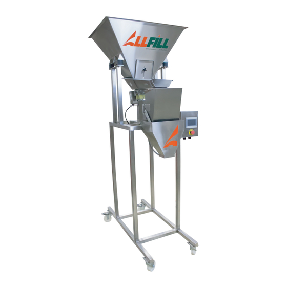
- Page 1 A.F.I. Publication: 1920118 Issue: 1 Date: January 2018 Model VF100e Model VF100e Vibratory Feeder Vibratory Feeder Installation & Maintenance Installation & Maintenance Manual Manual ALL-FILL, Inc. 418 Creamery Way Exton, PA. 19341 USA (610) 524-7350 · FAX (610) 524-7346 www.all-fill.com...
-
Page 3: Table Of Contents
Model VF100e Vibratory Feeder Installation & Maintenance Manual CONTENTS INTRODUCTION......................1 Model VF100e Vibratory Feeder ..................1 Figure 1 – Model VF100e Vibratory Feeder ............1 Components and Equipment..................2 Figure 2 – Model VF100e Feeder Components ............2 Infeed Hopper....................3 Figure 3 – Model VF100e Hopper..............3 Discharge Transition..................3... - Page 4 No liability is assumed with respect to the use of any information contained in this publication. While every precaution has been taken in the preparation of this publication, All-Fill, Inc .assumes no responsibility for errors or omissions nor is any liability assumed for damages result- ing from the use of information contained in this publication.
-
Page 5: Introduction
INTRODUCTION This section presents some introductory information about your All-Fill Model VF100e Vibratory Feeder. If you are new to All-Fill Filling and Feeding equipment, you should read this section first to familiarize yourself with the equipment before attempting any installation or production filling with the Model VF100e. -
Page 6: Components And Equipment
Model VF100e Vibratory Feeder Installation & Maintenance Manual Components and The Model VF100e Vibratory Feeder consists of the following major components. Locations of these components are shown in Figure 2. Equipment Figure 2 Model VF100e Feeder Components INFEED HOPPER DISCHARGE... -
Page 7: Infeed Hopper
Accumulated product dispensed into the weigh bucket is emptied into a removable Discharge Transition attached to the frame of the Model VF100e. The Discharge Transition also can serve as a mounting location for nozzles and chutes designed for specific contain- ers. -
Page 8: Product Feeder
Model VF100e Vibratory Feeder Installation & Maintenance Manual Product Feeder The Model VF100e includes a vibratory Product Feeder used to move product from the hop- per to the container. The Feeder consists of a Trough and Trough Bracket coupled by leaf springs to an electromagnetic drive. -
Page 9: Figure 6-Weigh Bucket Components
Model VF100e Vibratory Feeder Installation & Maintenance Manual Figure 6—Weigh Bucket Components 1920118.F6 AFI Publication 1920118 Issue: 1 January 2018... -
Page 10: Rotary Actuator
Model VF100e Vibratory Feeder Installation & Maintenance Manual Rotary Actuator The Weigh Bucket is opened and closed by the Rotary Actuator. A stepper motor drive pro- vides precise control by rotating a lever that actuates the linkage of the weigh bucket for opening and closing. -
Page 11: Cutoff Gate
1920118.F8 Control Panel All major functions of the Model VF100e Vibratory Feeder are performed at the Control Panel. This panel includes a custom-programmed Touch Screen Panel that provides menus, selections, settings, and controls used to test, adjust, and operate the equipment, as well as switches and indicator lamps used in machine operation. -
Page 12: Accessories
PANEL EMERGENCY STOP SWITCH 1920118.F9 Accessories The Model VF100e may include various accessories to be used in conjunction with the Vibratory Feeder. ● Flexible Product Gates ● Hopper Baffle ● Chute-Style Discharge Transition ● Bolt-On Nozzles and Chutes Installation and operating instructions for these type accessories will be provided separately and contained in the package of documentation supplied with the equipment. -
Page 13: Safety Considerations
Act is generalized to the extent that determination of compliance is a judgment of the local inspector. ALL-FILL, Inc. is not responsible for meeting the full requirements of OSHA in respect to the equipment supplied, or for any penalty assessed for failure to meet the requirements of the Occupational Safety and Health Act, as interpreted by an authorized inspector. -
Page 14: Warranty Information
Model VF100e Vibratory Feeder Installation & Maintenance Manual Warranty Information ALL-FILL, Inc. warrants each new item of its manufacture to be free from defects for a peri- od of one year from date of shipment. Used or reconditioned equipment will be warranted for a period of ninety (90) days from date of shipment. -
Page 15: Installation
Model VF100e Vibratory Feeder Installation & Maintenance Manual INSTALLATION This section contains information, procedures, and recommendations concerning the instal- lation of your ALL-FILL Model VF100e Feeder. Included are the following: Inspection and Unpacking For use when you initially receive your machine... -
Page 16: Inspection And Unpacking
Model VF100e Vibratory Feeder Installation & Maintenance Manual Inspection and Upon receipt of your ALL-FILL Model VF100e Feeder, you should initially inspect the ship- ping container(s) for any damage that may have occurred in transit. If damage is apparent, Unpacking notify the transport carrier in writing immediately describing the damage. -
Page 17: Electrical Requirements
The Model VF100e does not require compressed air, however, certain accessories and options (e.g., conveyor indexing, plungers, etc.) may be required If pneumatically-operated equipment is used with the Model VF100e, the installation site should include a source of compressed air before installing or operating the Model VF100e. -
Page 18: Installing The Model Vf100E Feeder
Model VF100e Vibratory Feeder Installation & Maintenance Manual Installing the Model Correct and careful installation of the ALL-FILL Model VF100e Feeder will result in proper, accurate filling production, lower maintenance, and reduced risk of machine downtime due VF100e Feeder to equipment failure. Installation is performed in the following, general sequence:... -
Page 19: Checkout And Operation
Model VF100e Vibratory Feeder Installation & Maintenance Manual Checkout and When the machine and any accessories have been installed and connected, the controls of the machine can be used to begin filling production. Operation Descriptions, instructions, and operating procedures for the controls are provided in a sepa- rate Users Manual. - Page 20 Model VF100e Vibratory Feeder Installation & Maintenance Manual AFI Publication 1920118 Issue: 1 January 2018...
-
Page 21: Service
Model VF100e Vibratory Feeder Installation & Maintenance Manual SERVICE This section presents the general servicing instructions, procedures, and recommendations for your ALL-FILL Model VF100e Vibratory Feeder. Included are: Preventative Maintenance Detailing the activities and recommended frequency of what to do to keep your machine in efficient, accurate operation. -
Page 22: Preventative Maintenance
Daily Maintenance The following should be checked on a daily basis after production shutdown or before start- up for the Model VF100e Feeder. Make sure ALL electrical power is disconnected before attempting this procedure. ● Inspect all electrical connections for loose or frayed wires that may cause a short cir- cuit. -
Page 23: Table I – Model Vf100E Troubleshooting
Model VF100e Vibratory Feeder Installation & Maintenance Manual Table I – Model VF100e Troubleshooting Problem Cause Correction Feeder operates too slow Line voltage below designated rating Increase line volt- age as designated on the nameplate Unit in contact with rigid object/surface Maintain proper... -
Page 24: Return And Repair Procedures
Spare Parts ALL-FILL offers pre-packaged Spare Part kits with the most commonly replaced items of the filling machine, based on the general type of filling machine. Additionally, a complete Bill of Material with all parts and assemblies is supplied with the relevant assembly drawings, sep- arately with each machine. -
Page 25: Adjusting Air Gap
Model VF100e Vibratory Feeder Installation & Maintenance Manual Adjusting Air Gap The air gap is the spacing that exists between the faces of the armature and core assem- blies. Proper adjustment of this space is extremely important for good feeder operation. -
Page 26: Measuring Stroke
Model VF100e Vibratory Feeder Installation & Maintenance Manual 1. Loosen the hex nut and insert a screwdriver into the slot on the end of the core. 2. Turn the core clockwise to narrow the air gap; or counterclockwise to widen the air gap. -
Page 27: Appendix
Model VF100e Vibratory Feeder Installation & Maintenance Manual APPENDIX · Stroke Gauge AFI Publication 1920118 Issue: 1 January 2018... - Page 28 Model VF100e Vibratory Feeder Installation & Maintenance Manual AFI Publication 1920118 Issue: 1 January 2018...
-
Page 29: Stroke Gauge
Model VF100e Vibratory Feeder Installation & Maintenance Manual Stroke Gauge CUT HERE CUT HERE FEEDER STROKE CUT HERE CUT HERE AFI Publication 1920118 Issue: 1 January 2018... - Page 30 Model VF100e Vibratory Feeder Installation & Maintenance Manual AFI Publication 1920118 Issue: 1 January 2018...
-
Page 31: Index
Model VF100e Vibratory Feeder Installation & Maintenance Manual INDEX Accessories, 8 Inspection and Unpacking, 12 Additional Information, 10 INST LL TION, 11 Adjusting Air Gap, 21 Installing the Model VF100e Feeder, 14 PPENDIX, 23 INTRODUCTION, 1 Checkout and Operation, 15... -
Page 32: Afi Publication 1920118 Issue: 1 January
Model VF100e Vibratory Feeder Installation & Maintenance Manual AFI Publication 1920118 Issue: 1 January 2018...
Need help?
Do you have a question about the VF100e and is the answer not in the manual?
Questions and answers