
Subscribe to Our Youtube Channel
Summary of Contents for Fayat Group Dynapac SCREED-CONTROL
- Page 1 OPERATION Dynapac SCREED-CONTROL -Pavemanager- 4812019539 (A5) 04-0616 Keep for later use in document compartment Valid for: _________________ bis _________________ _________________ bis _________________...
- Page 2 www.dynapac.com...
-
Page 3: Table Of Contents
Table of contents Table of contents Table of contents ................. 3 1 General information ................7 1.1 Information on the operating instructions ........7 1.2 Explanation of symbols ..............9 1.3 Limitation of liability ..............11 ... - Page 4 Table of contents 6.2 The display elements of the prop. laser receiver ......43 6.3 Malfunction displays ..............46 6.4 Levelling system operating modes ..........46 6.5 Levelling system operating variants ..........47 6.5.1 Standard operation .............. 47 ...
- Page 5 Table of contents 9.3.3 Controlling with the Sonic-Ski ® plus in cable sensing ..101 9.4 Working with the digital rotary sensor ........102 9.4.1 Installation and set-up ............102 9.4.2 Controlling with the digital rotary sensor ......103 ...
- Page 6 Table of contents 14 Help in the event of malfunctions ..........150 14.1 Safety instructions ..............150 14.2 Troubleshooting and malfunction rectification ......151 15 Definitions/Glossary ..............164 ...
-
Page 7: General Information
1 General information 1 General information 1.1 Information on the operating instructions These operating instructions contain basic notes which have to be General observed when operating and maintaining the remote control. The prerequisite of safe working is adherence to all safety instructions and handling instructions which are specified. - Page 8 1 General information We make every effort to ensure that these operating instructions are Modification correct and up to date. To maintain our technological advantage, rights reserved however, it may be necessary to carry out modifications to the product and its operation without prior notification. Under certain circumstances, these modifications may not correspond to these operating instructions.
-
Page 9: Explanation Of Symbols
1 General information 1.2 Explanation of symbols In these operating instructions, warnings are identified by means of Warnings symbols. These notes are introduced using signal words which express the extent of the hazard. Adhere to these notes under all circumstances and act cautiously to avoid accidents, personal injury and material damage. - Page 10 1 General information Tips and recommendations NOTE! … emphasises useful tips and recommendations plus information for efficient and trouble-free operation. Step-by-step instructions which are to be carried out by the operating Step-by-step personnel are numbered. 1) … 2) … 3) … ...
-
Page 11: Limitation Of Liability
1 General information 1.3 Limitation of liability All information and notes provided in these operating instructions have been compiled under consideration of the applicable standards and regulations, the state-of-the-art and our many years of knowledge and experience. The manufacturer accepts no liability for damages arising due to: ... -
Page 12: Spare Parts
1 General information 1.6 Spare parts Genuine spare parts and accessories authorised by the manufacturer serve to enhance safety. The use of other parts may limit the user's right to commission the product and may invalidate liability for consequences arising from use. CAUTION! Risk of injury due to incorrect spare parts! Incorrect, faulty or unauthorised spare parts may lead to damage,... -
Page 13: Disposal
1 General information 1.8 Disposal For transportation purposes, the products are protected with special Packaging packaging in the factory. This consists of environmentally compatible, easily separated materials and can be recycled. We recommend using recycling companies to dispose of the packaging material. -
Page 14: Warranty Regulations
1 General information 1.9 Warranty regulations These operating instructions do not contain any warranty commitments. The warranty regulations form part of the manufacturer's "Conditions of sale and delivery". 1.10 Customer service The manufacturer and its service network will be happy to provide technical information. -
Page 15: Basic Safety Instructions
2 Basic safety instructions 2 Basic safety instructions This section provides an overview of all important safety aspects for General optimal personnel protection and for safe and trouble-free operation. The instructions are intended to enable the owner and user to recognise any usage hazards in good time and to avoid these in advance wherever possible. -
Page 16: Incorrect Use
2 Basic safety instructions Danger due to improper use WARNING! Any use of the system which exceeds the proper use and/or any other use of the systems may lead to hazardous situations. Therefore: Only put the product to the proper use. 2.1.2 Incorrect use ... -
Page 17: Operating Boundaries
2 Basic safety instructions 2.2 Operating boundaries The remote control is suitable for use in an atmosphere which is permanently habitable for man. It must not be used in an aggressive or explosive environment. Local safety authorities and safety managers must be contacted by the owner before work is carried out in an endangered environment, in the vicinity of electrical systems or in similar situations. -
Page 18: Responsibility Of The Owner
2 Basic safety instructions 2.5 Responsibility of the owner The remote control is used in the commercial sector. The owner of the product is therefore subject to the legal duties of health and safety at work. In addition to the notes on health and safety at work contained in these operating instructions, adherence to the safety, accident prevention and environmental protection regulations applicable to the product's area of application is required. -
Page 19: Operating Personnel
2 Basic safety instructions 2.6 Operating personnel Risk of injury with inadequate qualification! WARNING! Improper handling of the product may lead to significant personal injury and material damage. Therefore: Have special activities carried out solely by the persons specified in the relevant chapters of these operating instructions. -
Page 20: Special Risks
2 Basic safety instructions 2.7 Special risks The residual risks arising on the basis of the hazard analysis are General specified in the following section. Observe the safety instructions listed here and the warnings in the other chapters of these operating instructions in order to reduce health risks and avoid hazardous situations. - Page 21 2 Basic safety instructions Projecting vehicle parts Risk of injury due to projecting vehicle parts! CAUTION! Retrofitted system components (e.g. sensors) may extend beyond the vehicle's typical dimensions. This may lead to injuries and material damage. Therefore: Make sure that the vehicle is operated by a qualified and experienced operator.
-
Page 22: Safety Facility
2 Basic safety instructions Inadequate securing Risk of injury due to inadequate securing! WARNING! Inadequate securing of the construction site and the location of a component, e.g. the laser transmitter, may lead to hazardous situations in road traffic and on the construction site. Therefore: ... -
Page 23: Behaviour In The Event Of Danger And Accidents
2 Basic safety instructions 2.9 Behaviour in the event of danger and accidents Preventative measures Always be prepared for accidents or fire! Keep first-aid facilities (first-aid kit, blankets, etc.) and fire extinguishers close at hand. Familiarise personnel with accident report, first-aid and rescue facilities. ... -
Page 24: Transportation, Packaging And Storage
3 Transportation, packaging and storage 3 Transportation, packaging and storage 3.1 Transportation inspection To ensure adequate protection during shipping, the products have been carefully packaged. On receipt, immediately check the delivery as regards completeness and transportation damage. Proceed follows event externally recognisable transportation damage:... -
Page 25: Transportation
3 Transportation, packaging and storage 3.2 Transportation When transporting your equipment to the operating location or in the field, always make sure that the product is transported in suitable transportation containers and that these are secured accordingly. Never transport the product loose in a vehicle. The product's function may be severely impaired by impacts and jolts. -
Page 26: Product Description
description 4 Product 4 Product description The remote control is a universal control and regulation system for construction vehicles. The extensive range of sensors for distance and slope monitoring, its extensive operating comfort and high operating safety make the remote control a flexible and efficient control system. -
Page 27: Design, System Overview And Function
5 Design, system overview and function 5 Design, system overview and function In this section, you will be familiarised with the design of the Dynapac General remote control and the basic way in which it functions. 5.1 Design A separate regulator (remote control) and at least one relevant sensor is required for each control circuit or side of the vehicle. -
Page 28: System Overview And Function
5 Design, system overview and function 5.2 System overview and function The Dynapac remote control offers all of the buttons required to control the system and optical displays from which the current status of the system can be read off at any time. - Page 29 5 Design, system overview and function ® The Sonic-Ski plus SKIS-1500 is a distance measurement sensor and operates with five ultrasonic sensors. A sixth sensor is used for temperature compensation. On sensing the ground, a mean value is formed from the values measured by the five ultrasonic sensors of the Sonic- ...
- Page 30 5 Design, system overview and function The Big Sonic-Ski ® again takes up the principle of mean ® value formation familiar from the Sonic-Ski plus. To achieve this, three sensors (e.g. 3x Sonic-Ski ® plus) are typically distributed over the length of the vehicle - or even beyond it with the assistance of a corresponding mechanical system.
- Page 31 5 Design, system overview and function The dual sonic sensor DUAS-1000 is a distance measurement sensor and operates using ultrasonic technology. The temperature of the value measured by the Dual-Sonic Sensor is compensated by means of a reference measurement versus a bracket with a defined distance parallel to the actual distance measurement.
- Page 32 5 Design, system overview and function Irrespective of which sensor is operated, the basic principle of regulation is always the same: The basic principle of regulation is continuous: measurement - comparison - adjustment A control circuit serves to set a specified physical variable (control variable) to a desired value (nominal value) and to maintain it at this value, regardless of any malfunctions which may occur.
-
Page 33: Controls And Displays, Operating Modes
6 Controls and displays, operating modes 6 Controls and displays, operating modes 6.1 Description of the remote control These instructions describe the operation of the Dynapac remote control and therefore the central component of the system. An understanding of basic operation of the remote control is required in the sections dealing with the operation of the individual sensors. -
Page 34: The Controls And Displays, Operating Modes
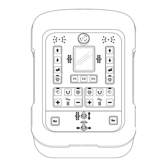
6 Controls and displays, operating modes 6.1.1 The controls and displays, operating modes Display EMERGENCY OFF LED display Left-hand levelling Right-hand system levelling system Function buttons Left auger Left conveyor (right conveyor) (right auger) Traction point adjustment Horn Horn Screed width... -
Page 35: Emergency Stop Switch
6 Controls and displays, operating modes The remote control's keypad has different functions depending on the side into which it is plugged. The function blocks marked in the following, in particular, differ in this case. Left remote control Right remote control Left-hand levelling Right-hand levelling system... -
Page 36: The Led Display
6 Controls and displays, operating modes 6.1.3 The LED display The LED arrow serves to visibly indicate the status of the relevant actuated valve output to the operator. The LED arrow is a particularly useful display when the operator is located a great distance away from the remote control and in strong sunlight. -
Page 37: The 3.5" Colour Display
6 Controls and displays, operating modes 6.1.4 The 3.5" colour display During normal operation, the sensor type selected for the relevant control circuits and its nominal and actual values are displayed on the large 240 (W) x 320 (H) pixel, backlit colour display. - Page 38 6 Controls and displays, operating modes The active sensor's actual value (5) and nominal values (7) are shown with prefixes, the nominal value additionally with a physical unit of measurement (8). The prefix indicates whether this involves a positive or a negative numerical value. Only the negative prefix, i.e.
-
Page 39: The Levelling System Operating Buttons
6 Controls and displays, operating modes 6.1.5 The levelling system operating buttons A few buttons are sufficient to operate the basic control functions. Up button & down button In automatic mode, the up button and the down button are used to change the nominal control value. -
Page 40: Operating Buttons F1-F3
6 Controls and displays, operating modes 6.1.6 Operating buttons F1-F3 Depending on the window or menu in which you are currently located, function buttons F1 to F3 have different assignments. Their relevant function is clearly described using a symbol above them in the display, making navigation in the individual menus clear and simple. -
Page 41: The Auger And Conveyor Operating Buttons
6 Controls and displays, operating modes 6.1.7 The auger and conveyor operating buttons As has already been described, two identical functions blocks, which are merely distinguished by a backlit symbol in the centre of the relevant button block, are available for controlling the auger and the conveyor. -
Page 42: Traction Point Adjustment Toggle Switch
6 Controls and displays, operating modes The plus and minus buttons: In automatic mode, the plus button and the minus button are used to change the nominal control value. If the "auger" or "conveyor" display menu is not active at the point in time at which the button is pressed, the menu is automatically started. -
Page 43: The Display Elements Of The Prop. Laser Receiver
6 Controls and displays, operating modes 6.2 The display elements of the prop. laser receiver The laser receiver is equipped with an LED arrow (1) - similar to that on the remote control. Depending on the operating mode to which the remote control to which it is connected is set, the function of the laser receiver LED arrow differs. - Page 44 6 Controls and displays, operating modes Displays of the prop. laser receiver in the manual mode“ In "manual" operating mode, the laser receiver LEDs are used to indicate to the operator how the sensor has to be shifted so that the laser beam hits the reception area centrally.
- Page 45 6 Controls and displays, operating modes Displays of the prop. laser receiver in the automatic mode In "automatic" operating mode, the laser receiver's LEDs are used to make the status of the relevant, actuated valve output visible to the operator. They now work in-line with the LED arrow on the remote control.
-
Page 46: Malfunction Displays
6 Controls and displays, operating modes 6.3 Malfunction displays If all of the LED arrow's LEDs flash simultaneously on the remote control, a malfunction is present. Often, these malfunctions do not involve genuine defects but indicate attempt operate vehicle under impermissible conditions. -
Page 47: Levelling System Operating Variants
6 Controls and displays, operating modes 6.5 Levelling system operating variants In the basic configuration set by the manufacturer, operation of the remote control can be set to three different variants. This operation then differs as follows: 6.5.1 Standard operation In "automatic"... -
Page 48: Operation With Auto Zeroing
6 Controls and displays, operating modes 6.5.3 Operation with auto zeroing In "automatic" operating mode, the nominal value is adjusted by 2 mm in the corresponding direction each time the up or down button is pressed. In this case, the screed is moved by the control system as specified. After 5 seconds, the value on the display is automatically accepted as the zero point, i.e. -
Page 49: Special Levelling System Functions
6 Controls and displays, operating modes 6.6 Special levelling system functions 6.6.1 Direct menu changeover Levelling system operation is usually required during paving. Definition If the remote control is not set to the operating window for the levelling system, the currently displayed menu must first be ended by pressing button F3. -
Page 50: Cross Operation
6 Controls and displays, operating modes To avoid undesired changes to the levelling system during this changeover, this first push of a button only ever leads to a return. After switching to the operating window, the buttons have their described levelling system functions again. Exception: "auto button": Each time it is pressed, the auto/manual button always switches directly between the two manual and automatic modes. - Page 51 6 Controls and displays, operating modes Mode 0: No cross operation is possible in this mode. Mode 1&2: In mode 1, it is only possible to show the display for the other side, while in mode 2 direct operation is also possible. As mode 1 and mode 2 differ just in this one point, the following description refers to mode 2: The following example describes how the...
- Page 52 6 Controls and displays, operating modes I.e. the display now shows the sensor used on the other side plus its actual and nominal values. To avoid undesired changes to the levelling system during this changeover, this first push of a button only ever leads to the activation of cross operation. The buttons only have their described levelling system functions again after switching to the operating window on the other side.
- Page 53 6 Controls and displays, operating modes Ending cross operation: Left remote control Right remote control If the levelling system operating window Ends automatically after 5 sec. on the left remote control is exited, this If no button on the left levelling system automatically leads to the cancellation button block is actuated within this time, of cross operation.
- Page 54 6 Controls and displays, operating modes Mode 3: In this mode, both sides of the levelling system are displayed at the same time. It is also possible to operate both sides in parallel. In addition, the crowning slope is also displayed.
-
Page 55: Display Of 2 Separate Control Circuits
6 Controls and displays, operating modes 6.6.3 Display of 2 separate control circuits Press any button for the "other" side to activate the menu with 2 control circuits. Pressing the first button for actuation does not bring 2. 40% about any adjustment. 9. - Page 56 6 Controls and displays, operating modes Press F2 to go to the view menu. The various windows in the view menu are described in detail in point "8.7 View menu". Press F3 to end the two-column visualisation and go back to the normal working menu. As well as activating the second control circuit by pressing any button of the "other"...
-
Page 57: Installation And Initial Commissioning
7 Installation and initial commissioning 7 Installation and initial commissioning Installation of the hardwired components, assembly of the brackets for General the various sensors and initial system commissioning are carried out by the manufacturer. The manufacturer has already adapted the controller parameters to the vehicle's valves and hydraulic system. -
Page 58: Operation In General
8 Operation in general 8 Operation in general The descriptions contained in this section are intended to guide you General when operating the product as operating or production equipment. This includes Safe operation of the product Exploitation of the possibilities offered by the product ... -
Page 59: Initial Steps
8 Operation in general 8.2 Initial steps The chapter entitled "Initial steps" contains information on switching the system on and a description of sensor selection. Visually inspect the remote control, the sensors and the cables each Before time before switching on. switching on Check all system components for obvious damage, and to ensure that the connection cable connections are securely seated and correctly... - Page 60 8 Operation in general Note on side recognition: Correct side recognition is important for error-free interaction of the two remote controls, left and right. Therefore: Make sure that side recognition takes place correctly when starting up the system. If the sensor with which work was last carried out is connected again, the view in the display then switches to the operating window If the sensor which was last used has been changed over or...
-
Page 61: Sensor Selection
8 Operation in general 8.2.2 Sensor selection If the sensor which was last used has been exchanged for a different sensor or several sensors are perhaps connected to one side at the same time, the sensor desired for the relevant operation can be selected in "Sensor selection". - Page 62 8 Operation in general The new sensor is ready to operate. 2 . 4 0 % 2 . 4 0 2 . 4 0...
- Page 63 8 Operation in general The following sensors are available when the system is fitted with the Overview of maximum equipment: sensor symbols No sensor ® Sonic-Ski plus SKIS-1500 in ground sensing Sonic-Ski ® plus SKIS-1500 in cable sensing Digi-Slope Sensor SLOS-0150 Digi-Rotary Sensor ROTS-0300 Dual-Sonic Sensor DUAS-1000 Prop.
-
Page 64: Modification
8 Operation in general 8.3 Modification For sensor exchange, set-up work or work on the sensors, always switch the remote control to "manual" operating mode. 8.4 Switching off Due to safety reasons, the remote control is always initially switched to "manual"... -
Page 65: Auger Menu
8 Operation in general 8.5 Auger menu Different operating modes are available for the auger drive's control system. The Screed Control System described in these instructions uses a material sensor to determine the distance from the material and monitors all button operations on the corresponding keypad block. -
Page 66: Auto Control System With Material Sensor
8 Operation in general 8.5.2 AUTO control system with material sensor A material sensor mounted on the side board measures the distance up Function to the material conveyed by the auger. In AUTO operating mode, the control system's objective is to keep this distance constant so that sufficient material is always available in front of the screed. -
Page 67: Auto Control System Without Material Sensor
8 Operation in general 8.5.3 AUTO control system without material sensor If no material sensor is connected, AUTO mode has a slightly different Function function. In this case, the auger always rotates at a constant speed. This speed can be adjusted via the nominal value. Switching on ... -
Page 68: Reverse Control System
8 Operation in general 8.5.4 Reverse control system In this mode, the auger is actuated at full speed in the reverse direction. Function This mode is activated by pressing the "reverse" button. Switching on Reverse mode is only maintained as long as the button is kept depressed, and ends automatically on releasing the button. -
Page 69: Conveyor Menu
8 Operation in general 8.6 Conveyor menu Different operating modes are available for the conveyor drive's control system. The Screed Control System described in these instructions monitors all button operations on the corresponding keypad block. This information is transmitted to the higher-level control system, where it is processed. -
Page 70: Auto Control System With Material Sensor
8 Operation in general 8.6.2 AUTO control system with material sensor A material sensor mounted above the conveyor measures the distance Function up to the material conveyed by the conveyor. In AUTO operating mode, the control system's objective is to keep this distance constant so that sufficient material is always available in front of the screed. -
Page 71: Auto Control System Without Material Sensor
8 Operation in general 8.6.3 AUTO control system without material sensor If no material sensor is connected, AUTO mode has a slightly different Function function. In this case, the conveyor always runs at a constant speed. This speed can be adjusted via the nominal value. Switching on ... -
Page 72: Reverse Control System
8 Operation in general 8.6.4 Reverse control system In this mode, the conveyor is actuated at full speed in the reverse Function direction. This mode is activated by pressing the "reverse" button. Switching on Reverse mode is only maintained as long as the button is kept depressed, and ends automatically on releasing the button. - Page 73 8 Operation in general Brief overview of the view menu: Lateral slope display Layer thickness display Tamper frequency Vibration Screed temperature ° 1 0 . 1 5 11 .2 1 2 5 20 00 °C m i n m i n 2 .
- Page 74 8 Operation in general Layer thickness display: This window appears only if the layer thickness has been activated, and the corr. Sensors are connected. (See also 8.11.1 Configuration menu) 11. 2 Quick adjustment of the layer thickness display: Adjustment of the displayed layer thickness as following: Press and hold ENTER key, and to adjust the value in parallel...
- Page 75 8 Operation in general The other windows in the view menu (tamper frequency and vibration) have the same structure. The operating mode cannot be changed over in the menu for screed temperature. Tamper frequency Vibration Screed temperature 1 2 5 2 0 0 0 °...
-
Page 76: Crowning Menu
8 Operation in general 8.8 Crowning menu Crowning control can be carried out in 3 different operating modes. Manual adjustment Auto adjustment "Travel-dependent" adjustment The selection menu has a differing structure to take account of the fact that the auto adjustment and the travel-dependent adjustment can only be activated under certain conditions. -
Page 77: Manual Control System
8 Operation in general 8.8.1 Manual control system Navigate to the crowning in the view menu. Select manual adjustment using the up/down buttons. Confirm the selection with the enter button. ATTENTION! The crowning is adjusted directly by pressing the up/down buttons! If a crowning sensor is present, the currently 0. -
Page 78: Auto Crowning Adjustment
8 Operation in general 8.8.2 Auto crowning adjustment Auto adjustment can only be selected if a sensor is available. Select auto adjustment using the up/down buttons. Confirm the selection with the enter button. Use the up/down buttons to set the nominal value to the desired crowning slope. -
Page 79: Travel-Dependent Adjustment
8 Operation in general 8.8.3 Travel-dependent adjustment Select "travel-dependent" adjustment using the up/down buttons. "Travel-dependent" adjustment can only be selected if travel information is available on the bus and the crowning sensor is present. Confirm the selection with the enter button. Use the up/down buttons to enter the nominal value for the desired crowning slope. - Page 80 8 Operation in general Security check: Only when the start button F2 is pressed again, the travel- 50. 0 dependent roof profile control is activated. 2. 40% F1 = Change the display with 2 control circuits 1. 00 F2 = Start F3 = Exit the crowning window to the main menu 1.
-
Page 81: Basic Screed Width
8 Operation in general 8.9 Basic screed width This menu is used for input of the basic screed width. If the system is equipped with screed width measurement, the width entered here together with the two measured Vario screed widths results in the total working width. -
Page 82: User Menu
8 Operation in general 8.11 User menu Important parameters and setting options for adapting the remote control and for the behaviour of the control system are summarised in the user menu. The user menu is available in both "manual" operating mode and "automatic"... - Page 83 8 Operation in general The other windows in the user menu include: Display brightness The brightness of the display backlighting can be set to ensure that the XX . X display remains clearly legible even in the event of unfavourable light conditions.
- Page 84 8 Operation in general Sensitivity tables for the various sensors: Sensors Sensitivity Dead band Prop band (mm) (mm) Sonic-Ski ® plus 18.0 Big Sonic-Ski ® 16.0 Dual sonic sensor, 14.0 Prop. laser receiver Power mast with 12.0 laser receiver 10.0...
- Page 85 8 Operation in general Control window This menu item is only shown when a distance sensor is currently selected as the active sensor, as it only has an effect on this sensor type. Transient changes in a sensor's measured value may occur due to diverse reasons.
- Page 86 8 Operation in general The size of the control window, which is positioned symmetrically around the working point, can be set. Depending on which physical unit of measurement has been set for distance measurement, the setting is carried out in steps of 0,1cm, 0,1inch or 0,01feet.
-
Page 87: Configuration Menu
8 Operation in general 8.11.1 Configuration menu The configuration menu forms part of the user menu. Here, the sensors' physical units of measurement and the appearance of the operating window are defined and the layer thickness display is configured if necessary (if possible due to the sensor constellation). - Page 88 8 Operation in general Layer thickness display The configuration menu's layer thickness display item is only shown if a layer thickness display is at all possible in the display menu due to the current sensor constellation on the CAN bus. First define whether you would like to activate or deactivate the layer thickness display.
- Page 89 8 Operation in general Units of measure for distance measurement Select the resolution and the physical unit of measurement for the distance measurements from the available alternatives. The selection made here applies to all distance measurement sensors. Select the desired unit of measurement using the up/down buttons.
- Page 90 8 Operation in general Configuration of the operating windows X X. X The following windows can be customised by the user: Operating window Auto return Info line Operating window: Use the up/down buttons to select the appearance of the operating window from the available alternatives;...
- Page 91 8 Operation in general Auto return: The next configuration menu can be used XX. X to adjust a timed return from the submenus to the main menu. The range is 0 - 10 sec. 0 = no return s ec >0 = return time The default setting is 5 sec.
- Page 92 8 Operation in general You can select the following values for the info line: Overview info line Actual value of the digital slope sensor (= default) Actual values of all other currently connected sensors, e.g. Sonic-Ski ® Actual crowning measurement (if sensor present) Distance covered by the vehicle Material planning - quantity of material still required...
-
Page 93: Levelling System Operation
9 Levelling system operation 9 Levelling system operation 9.1 Working with the digital slope sensor 9.1.1 Installation and set-up The digital slope sensor is mounted between the traction arms on the crossbeam slightly downstream of the screed. Four securing holes are provided for installation on the sensor's mounting plate. - Page 94 9 Levelling system operation The following text describes how the numerical value of a set nominal slope specification is reset to the actual value of the result when working in automatic mode. Step 3 Step 1 Step 2 The system is set to automatic The working result is Press and hold down the mode.
-
Page 95: Controlling With The Digital Slope Sensor
9 Levelling system operation 9.1.3 Controlling with the digital slope sensor 1) Use the auto/ 2) Select the digital slope 3) Move the screed to the manual button to sensor as described. working position using the switch the controller to up/down buttons or the toggle ... -
Page 96: Calibration To Zero
9 Levelling system operation 9.2 Calibration to zero Before working with the different distance sensors is described over the Definition next few pages, the term calibration to zero must first be explained at this point. During each new operation or whenever a distance sensor has been installed or reinstalled, its current measured value should be calibrated to zero. - Page 97 9 Levelling system operation Calibration to zero is only effective for distance sensors. To this end, the remote control must also be in the manual mode. Once the screed, traction point and sensor(s) have been set to the Calibration calibration height, proceed as follows during calibration to zero: 3) Select the distance sensor to be calibrated from the remote control's sensor selection.
-
Page 98: Working With The Sonic-Ski ® Plus
9 Levelling system operation ® 9.3 Working with the Sonic-Ski plus 9.3.1 Installation and set-up For ground sensing, the Sonic-Ski ® plus must be operated Installation longitudinally to the vehicle's direction of travel (mean value formation). direction for ground sensing Direction of travel ®... - Page 99 9 Levelling system operation The optimal working area for the Sonic-Ski ® plus with ground and cable Working area sensing lies between 30 cm and 40 cm. In this range, the actual value shown on the remote control display is constantly on;...
-
Page 100: Controlling With The Sonic-Ski ® Plus In Ground Sensing
9 Levelling system operation ® 9.3.2 Controlling with the Sonic-Ski plus in ground sensing 1) Use the auto/manual 3) Move the screed to the 5a) Press the enter button. The nominal value has a button to switch the controller working position for to "manual"... -
Page 101: Controlling With The Sonic-Ski ® Plus In Cable Sensing
9 Levelling system operation ® 9.3.3 Controlling with the Sonic-Ski plus in cable sensing 1) Use the auto/manual 3) Move the screed to the 5a) Press the enter button. button to switch the working position for The nominal value has a controller to "manual"... -
Page 102: Working With The Digital Rotary Sensor
9 Levelling system operation 9.4 Working with the digital rotary sensor 9.4.1 Installation and set-up The digital rotary sensor "drags" the sensor arm with the aid positioned on it behind itself. Two different aids are available for sensing the various references. The height of the digital rotary sensor should be set in such a way that the flattened side of its sensor axle is positioned vertically to the reference when the sensing tube or sensing shoe is in contact. -
Page 103: Controlling With The Digital Rotary Sensor
9 Levelling system operation 9.4.2 Controlling with the digital rotary sensor 1) Use the auto/manual 3) Move the screed to the 5a) Press the enter button. The nominal value has a button to switch the working position for controller to "manual" calibration to zero using the black background and operating mode. -
Page 104: Working With The Dual Sonic Sensor
9 Levelling system operation 9.5 Working with the dual sonic sensor 9.5.1 Installation and set-up The ultrasonic pulses emitted by the dual sonic sensor have more club- shaped characteristics; i.e. the sound beam becomes wider the further it moves away from the sensor. When working with the dual sonic sensor, clearance of >... -
Page 105: Controlling With The Dual Sonic Sensor
9 Levelling system operation 9.5.2 Controlling with the dual sonic sensor 1) Use the auto/manual 3) Move the screed to the 5a) Press the enter button. The nominal value has a button to switch the controller working position for to "manual"... -
Page 106: Working With The Big Sonic-Ski
9 Levelling system operation 9.6 Working with the Big Sonic-Ski ® 9.6.1 Installation and set-up The manufacturer offers installation instructions in which the installation Mechanical ® of the Big Sonic-Ski's mechanical system is exhaustively described. system (Also see section "1.5 Other applicable documents" in this regard). On vehicles with a CAN bus wired in the factory, the connection of Electrical ®... - Page 107 9 Levelling system operation Always connect the front most sensor in the direction of travel to output 1, the centre sensor to output 2 and the rear sensor to output 3 ® of the "Big Sonic-Ski distributor box". The numbering of the sensors in the sensor symbols also refers to this connection sequence.
- Page 108 9 Levelling system operation ® Only ground sensing is generally possible with the Big Sonic-Ski Installation During operation, all Sonic-Ski ® plus must therefore be aligned direction of the longitudinally to the vehicle's direction of travel (mean value formation). ® Sonic-Ski plus sensors...
-
Page 109: Controlling With The Big Sonic-Ski
9 Levelling system operation ® 9.6.2 Controlling with the Big Sonic-Ski 1) Use the auto/manual 3) Move the screed to the 5a) Press the enter button. button to switch the working position for The nominal value has a controller to "manual" calibration to zero using the black background and operating mode. -
Page 110: Working With The Prop. Laser Receiver
9 Levelling system operation 9.7 Working with the prop. laser receiver 9.7.1 Safety instructions Laser beams Risk of eye injury due to laser beams! CAUTION! Laser transmitters operate with high-intensity light beams. Looking directly into the laser beam may lead to eye injuries. Therefore: ... -
Page 111: Installation And Set-Up
9 Levelling system operation 9.7.2 Installation and set-up The following points should be observed under all circumstances when General installing the laser receiver: No obstacles (e.g. cables) may be located in front of the sensor; Laser transmitters and laser receivers must always be "clearly visible"... - Page 112 9 Levelling system operation The prop. laser receiver can be moved freely on its mast. Use the sensor's integrated positioning aid to set the laser receiver up, and move the sensor or the mast so that the laser beam hits the reception area centrally.
-
Page 113: Controlling With The Prop. Laser Receiver
9 Levelling system operation 9.7.3 Controlling with the prop. laser receiver 1) Use the auto/manual 3) Move the screed to the 5a) Press the enter button. The nominal value has a button to switch the working position for controller to "manual" calibration to zero using the black background and operating mode. -
Page 114: Working With The Power Mast And Prop. Laser Receiver
9 Levelling system operation 9.8 Working with the power mast and prop. laser receiver 9.8.1 Safety instructions Electrical current Danger due to electrical current! DANGER! When working with a laser mast or the power mast in the immediate vicinity of electrical systems, e.g. overhead cables or electric railways, a life-threatening risk exists due to electric shock. -
Page 115: Installation And Set-Up
9 Levelling system operation 9.8.2 Installation and set-up The following points should be observed under all circumstances when General working with a power mast with a laser receiver mounted on it: No obstacles (e.g. cables) may be located in front of the sensor; ... -
Page 116: The Mast Menu
9 Levelling system operation When working with a power mast, 2 different procedures for setting up the laser receiver are available to the operator. Both can be carried out comfortably on the remote control. 1) The mast can be moved manually and the laser receiver can be set up using its positioning aid or 2) The laser beam search can be carried out... -
Page 117: Calling Up The Mast Menu
9 Levelling system operation 9.8.4 Calling up the mast menu Press function button F2 ( ) in the operating window. 9. 8 2. 3 The mast menu window opens. symbol appears at the top left of the window. Select the desired menu item using the up/down buttons and confirm the selection using the enter button. -
Page 118: Moving The Power Mast Manually
9 Levelling system operation 9.8.5 Moving the power mast manually Select the "Moving the power mast manually" function in the mast menu. The selection has a black background. Confirm the selection with the enter button. Press function button F3 ( ) to leave the menu. The illustrated window opens. -
Page 119: Automatic Laser Beam Search
9 Levelling system operation 9.8.6 Automatic laser beam search Select the "Automatic laser beam search" function in the mast menu. The selection has a black background. Confirm the selection with the enter button. Press function button F3 ( ) to leave the menu. The illustrated window opens. - Page 120 9 Levelling system operation One of the following symbols is shown at the position of the grey rectangle: = on call-up = whilst searching up = whilst searching down = laser beam found = laser beam not found Note on height measurement using the power mast: The third menu item is used for height measurement with the machine.
-
Page 121: Controlling With The Power Mast And Prop. Laser Receiver
9 Levelling system operation 9.8.7 Controlling with the power mast and prop. laser receiver 1) Use the auto/manual button to 3) Move the screed to 5a) Press the enter button. If switch the controller to "manual" the working position the laser beam is located in operating mode. -
Page 122: Working With The 3D Tps
9 Levelling system operation 9.9 Working with the 3D TPS 9.9.1 Installation and set-up Commission the MOBA 3D TPS system according to its operating instructions. A description of the installation, wiring and configuration of the system components, ascertaining the vehicle dimensions and entering them in the 3D software, calibration of the mast slope sensor and above all a description of how the 3D software works goes beyond the scope of these operating instructions. -
Page 123: Controlling With The 3D Tps
9 Levelling system operation 9.9.2 Controlling with the 3D TPS 1) Use the auto/manual button to 3) Move the screed to the 4a) Press the enter switch the controller to "manual" working position for button. The nominal value has operating mode. -
Page 124: Working With The 3D Gnss
9 Levelling system operation 9.10 Working with the 3D GNSS The positioning accuracy of the GNSS signal is limited to the range of just a few centimetres so that 3D GNSS systems are only conditionally suitable for certain applications. 9.10.1 Installation and set-up Commission the MOBA 3D GNSS system according to its operating instructions. -
Page 125: Controlling With The 3D Gnss
9 Levelling system operation 9.10.2 Controlling with the 3D GNSS 1) Use the auto/manual 3) Move the screed to the 4a) Press the enter button to switch the controller working position for button. The nominal value has to "manual" operating mode. calibration to zero using the up/down buttons on the a black background... -
Page 126: Working With The 3D Slope Sensor
9 Levelling system operation 9.11 Working with the 3D slope sensor The 3D slope sensor is not an additional sensor in the actual meaning of the word. The digital slope sensor already described above is used to register the actual value of the tool slope. In contrast to the digital slope sensor, when working with the 3D slope sensor the nominal value is not entered manually but defined automatically by the 3D system according to the specific position. -
Page 127: Controlling With The 3D Slope Sensor
9 Levelling system operation 9.11.3 Controlling with the 3D slope sensor 1) Use the auto/manual 2) Select the 3D slope sensor 3) Use the up/down button to switch the controller as described. buttons on the controller to "manual" operating mode. to move the screed to the ... -
Page 128: Travel-Dependent Working With The Digital Slope Sensor
9 Levelling system operation 9.12 Travel-dependent working with the digital slope sensor This is not an additional sensor in the actual meaning of the word The digital slope sensor already described above is used to register the actual value of the tool slope. In contrast to the digital slope sensor, in travel-dependent working with the digital slope sensor the nominal value is not entered manually but defined automatically by the system according to the covered distance. -
Page 129: Installation And Set-Up
9 Levelling system operation 9.12.1 Installation and set-up The digital slope sensor is mounted between the traction arms on the crossbeam slightly downstream of the screed. (for further installation details please also refer to chapter "9.1.1 Installation and set-up") 9.12.2 Actual value reset The actual value reset synchronises the measured value of the digital slope sensor with the actual slope of the tool. - Page 130 9 Levelling system operation Enter the required target slope with the up/down buttons. (The target slope also appears in the info line). 2. 00% 1. 00 Press button F2 … 2. 00 … the travel input window opens. 50. 0 Use the up/down buttons to enter the distance to which the 2.
- Page 131 9 Levelling system operation The travel-dependent slope control is active. During travel-dependent adjustment, the remaining distance to be covered is displayed in the header. 49. 9 Display of the target value to the end 2. 00% Currently measured actual value 1.
-
Page 132: Operating The Emergency Control
10 Operating the emergency control 10 Operating the emergency control The emergency control, also called emergency function, is only General intended in the event of possible failure of the operating panel on the control platform. In this case, it should be possible for the emergency control to activate at least the basic functions of the machine using the remote controls. -
Page 133: Activating The Emergency Control
10 Operating the emergency control 10.1 Activating the emergency control The emergency functions are the second from last menu in the view menu. The call-up and structure of the menu sequences are already described in detail in point "8.7 View menu". Call-up: 5. - Page 134 10 Operating the emergency control Activating the emergency functions: The "Lift auger" menu is followed by the menu for releasing the remote control. Open emergency functions: Press ENTER to open the emergency functions. Navigation in the menu: Navigate through the menu using function buttons F1 ( ) and F2 ( ).
-
Page 135: Functions Of The Emergency Control
10 Operating the emergency control 10.2 Functions of the emergency control Diesel engine speed: The value can be changed using the up/down buttons. Navigation in the menu: Navigate through the menu using function buttons 2200 F1 ( ) and F2 ( ). End menu: Press function button F3 ( ) to leave the menu. - Page 136 10 Operating the emergency control Hopper: The left hopper can be opened or closed using the up/down buttons of the left button block. The up/down buttons on the right button block open and close the right hopper. Navigation in the menu: Navigate through the menu using function buttons F1 ( ) and F2 ( ).
-
Page 137: Material Calculation
11 Material calculation 11 Material calculation Material calculation is the last menu in the view menu. General The call-up and structure of the menu sequences are already described in detail in point "8.7 View menu". The material calculation menu offers you a choice of the following two Function functions: Calculating the applied material... - Page 138 11 Material calculation After making the selection, first the overview page appears. Covered distance Entered course thickness Calculated volume of material Calculated weight The values shown here are calculated on the basis of the following values: - Distance - Working width - Course thickness - Material density Press F2 to enter these values.
- Page 139 11 Material calculation Enter the paved course thickness. Any measurements for the course thickness available in the system are used for this calculation. F2 takes you to the next input. Enter the paved working width (screed width). Any measurements for the width available in the system are used for this calculation.
- Page 140 11 Material calculation After all values have been entered once, the overview shows the amount of material already applied..
-
Page 141: Advance Material Planning (Calculation)
11 Material calculation 11.2 Advance material planning (calculation) Use the up/down buttons to calculate the advance material planning. After making the selection, first the overview page appears. Distance still to be covered Entered course thickness Calculated volume of material Calculated weight The values shown here are calculated on the basis of the following values: - Distance... - Page 142 11 Material calculation Enter the distance to be covered to the target. F2 takes you to the next input. Enter the planned course thickness. If there are measurements for the course thickness already in the system, the current measurement is frozen in the display when you call up the input window.
- Page 143 11 Material calculation Finally, enter the material density "ρ" to convert the volume into weight. Press F2 to go back to the overview. After all values have been entered once, the overview shows the amount of material still required. When the vehicle moves, this automatically reduces the distance shown in the header.
-
Page 144: Changing The Units Of Measurement
11 Material calculation 11.3 Changing the units of measurement The units of the various parameters for advance material planning and for calculating the applied material are always the same. 10. 5 10. 5 Press F1 to go from the overview page to changing the units. - Page 145 11 Material calculation Changing the units of measurement for course thickness. There is a choice between: Centimetre (cm) Inch (") F2 takes you to the next input. Changing the units of measurement for the paving width. There is a choice between: ...
- Page 146 11 Material calculation Changing the units of measurement for material volume. There is a choice between: Cubic meter (m³) Cubic foot (ft³) Cubic yard (yd³) Register ton (reg. tn) F2 takes you to the next input. Changing the units of measurement for material weight.
-
Page 147: External Levelling
12 External levelling 12 External levelling The levelling function is integrated completely in the remote control. General If external levelling is required instead, the system has to be changed over accordingly at the driver's dashboard. 2. 40% Internal levelling is deactivated for external 9. -
Page 148: Servicing And Maintenance
13 Servicing and maintenance 13 Servicing and maintenance The product has been developed for high operating reliability. General Only a minimum of effort is required to maintain the product. All electronic components are contained in robust housings to avoid any possible mechanical damage. -
Page 149: Cleaning And Drying
13 Servicing and maintenance 13.2 Cleaning and drying Cleaning work on the product can be carried out by laymen if these adhere to the following specifications. Switch off the product; Devices: Pour commercially available plastic cleaner onto a soft, lint-free cloth;... -
Page 150: Help In The Event Of Malfunctions
14 Help in the event of malfunctions 14 Help in the event of malfunctions When working with the remote control, a distinction is made between General warning and error messages. This section provides information on the measures which can or must be implemented if a warning or error message occurs in the system. -
Page 151: Troubleshooting And Malfunction Rectification
14 Help in the event of malfunctions 14.2 Troubleshooting and malfunction rectification Warning messages appear in the operating window at the position of Warning the currently active sensor's actual value. messages In the case of sensor combinations (Big Sonic-Ski ® , power mast with laser receiver, etc.) a separate warning message is shown for each individual component. - Page 152 14 Help in the event of malfunctions General: Cause: The sensor last used has been exchanged or removed; Remedy: Select another sensor in the sensor selection or check why the sensor is no longer available; Cause: Positive or negative deviation of the active sensor's measured value from the permissible measuring range or the power mast has reached the upper or lower stop of its mechanical adjustment range;...
- Page 153 14 Help in the event of malfunctions Specifically when working with TPS (total station): Cause: The total station is not installed horizontally; Control outputs: The outputs are locked in automatic mode; Remedy: Mount the tripod with the total station so that the air bubble comes to rest in the middle of the spirit level air bubble;...
- Page 154 14 Help in the event of malfunctions Specifically when working with GNSS (Global Navigation Satellite Systems): Cause: Restricted accuracy of the measurement; partial shading may possibly result in a poor satellite link; Control outputs: The outputs are still actuated in automatic mode; Remedy: Press any button to acknowledge the error message;...
- Page 155 14 Help in the event of malfunctions Error messages differ from warning messages due to the fact that they Error messages are always displayed in combination with the signal colour "red". In contrast to warnings, which usually only appear temporarily and disappear again automatically, error messages frequently indicate defects.
- Page 156 14 Help in the event of malfunctions Cause: The connection between the Screed Controller and the higher- C A N - E R R level control system is interrupted. Control outputs: No further control signals whatsoever can be transmitted to the tractor. Remedy: CAN connection must be restored, as continuing to work is otherwise impossible.
- Page 157 14 Help in the event of malfunctions General: Cause: The connection to the active sensor has suddenly been lost during operation; Control outputs: The outputs are locked in automatic mode; Remedy: Check the sensor's connection cable for damage and exchange it if necessary; Exchange the sensor;...
- Page 158 14 Help in the event of malfunctions Cause: Although one of the remote control's outputs is actuated, the power mast does not move - the mast is stuck or blocked; Control outputs: The outputs are locked in automatic mode; Remedy: Check whether an obstacle is located in the mast's path, the mast is possibly bent or the mast's moving mechanism is severely soiled and therefore blocked;...
- Page 159 14 Help in the event of malfunctions Cause: Positive deviation from the laser transmitter's specified maximum rotational speed (>20 Hz [revolutions per second]); Control outputs: The outputs are locked in automatic mode; Remedy: Reduce the laser transmitter's rotational speed if it is equipped with a speed control;...
- Page 160 14 Help in the event of malfunctions Specifically when working with TPS (total station): Cause: The total station has lost the prism, thus interrupting the direct "view" of the prism; Control outputs: The outputs are locked in automatic mode; Remedy: The total station automatically starts target tracking again after measurement was interrupted;...
- Page 161 14 Help in the event of malfunctions Cause: The radio link between the total station and the system computer is interrupted; Control outputs: The outputs are locked in automatic mode; Remedy: Check the wiring and the power supply for the radio devices; Check the LEDs on the total station and on the radio device that visualise the radio link;...
- Page 162 14 Help in the event of malfunctions Cause: The radio link between basis station and GNSS receiver on the vehicle is interrupted; Control outputs: The outputs are locked in automatic mode; Remedy: Check the wiring and the power supply for the radio devices; Make sure that that the base station is working and that there are no screening metallic surfaces directly in front of it;...
- Page 163 14 Help in the event of malfunctions Side recognition error: Display: The side recognition indicates with a flashing arrow that both remote controls have imported the same side recognition. Function: The remote controls remain in the error menu, i.e. operation is not possible. Causes: The lead cable for the remote control or the plug connector to the connection box is damaged or has a loose contact;...
-
Page 164: Definitions/Glossary
15 Definitions/Glossary 15 Definitions/Glossary Definition Definition Actual value The actual value measured by a sensor, e.g. the distance of a gap sensor to the reference point or the inclination measured by a slope sensor. Actuator Converts control signals into (usually) mechanical work, i.e. movement;... - Page 165 Parts & Service Training We offer our customers training courses on DYNAPAC equipment in our dedicated factory training centre. We hold regular training courses in this training centre as well as courses outside the scheduled hours. Service Please contact one of our responsible service outlets if you encounter any operational problems or have enquiries about spare parts.
- Page 166 www.dynapac.com...
Need help?
Do you have a question about the Dynapac SCREED-CONTROL and is the answer not in the manual?
Questions and answers