Table of Contents
Advertisement
Quick Links
Advertisement
Table of Contents

Summary of Contents for Anhui Pan-sino BL330E
-
Page 2: General Safety Instructions
GENERAL SAFETY INSTRUCTIONS EXTREME CAUTION SHOULD BE USED IN OPEATION ALL POWER TOOLS. KNOW YOUR POWER TOOL, BE FAMILIAR WITHITS OPEARTION. READ THE OWNER’S MANUAL AND PRACTICE SAFE USAGE PROCEDURES AT ALL TIMES. ◆ CONNECT your machine ONLY to the matched and specified power source. ◆... -
Page 3: Specifications
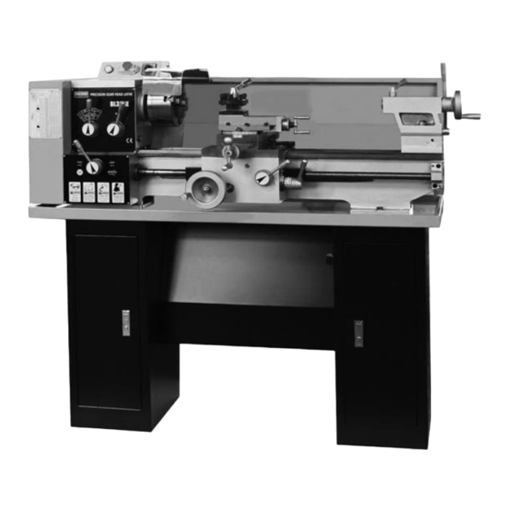
BL330E PRECISION GEAR HEAD LATHE As part of the growing line of metalworking equipment, we are proud to offer the BL330E Metal Lathe. The name guarantees ANHUI PAN-SINO. By following the instructions and procedures laid out in this owner’s manual, you will receive years of excellent service and satisfaction. The BL330 is a professional tool and like all power tools, proper care and safety procedures should be adhered to. -
Page 4: Illustrated Features
Illustrated Features Fig 1. Driving system drawing. 01. Input Pulley 21. Gear 02. Gear Change 22. Gear 03. Gear Change 23. Gear 04. Gear Change 24. Worm Gear 05. Gear Change 25. Worm 06. Gear 26. Gear 07. Gear 27. Gear 08. - Page 5 Lifting & Installation It is recommended that this machine is lifted by the use of a crane or hoisting mechanism as it is very heavy. Fig 2. Lifting drawing. Lifting & Installation Please refer to figure 3 when installing this machine. As this lathe is for the most part pre-assembled at the factory, there is not a great deal of assembly for the end user.
- Page 6 Lubrication Positions Fig 4. Lubrication positions drawing. Refer to the Lubrication chart on the following page in order to properly lubricate and maintain your Lathe. Proper lubrication of any tools, especially Metal Lathes should not be ignored. Lubrication Positions No. Lubrication Position Located part Located Lubrication Oil...
-
Page 7: Grounding Instructions
Electrical System Drawing ZH-A V 1 (Z 1 ) KJD17B ∽ U< Y L -9 0 L 4 1. 1 K W AC220V/240V 50HZ/60HZ Fig5. Electric System Drawing (SINGLE PHASE) Fig6. Electric System Drawing (THREE PHASES) Grounding Instructions In the event of a malfunction or breakdown, grounding provides the path of least resistance for electrical current and reduces the risk of electrical shock. -
Page 8: Operating Controls
Thread & Feed Table Cutting threads and feeding movement can be performed by the manual use of the change gears and handle (refer to Operating Controls) Thread & Feed Chart Fig. 7 Operating Controls Fig 7. Thread & Feed Chart... - Page 9 REFER TO THE DIAGRAM BELOW FOR THE BL330E operation controls. Fig 8. Operation Parts Fig. 1. Handler of Spindle Speed Change A 2. Handler of Spindle Speed Change B 3. Change Gear Box 4. Power Indictor 5. Emergency Stop Switch 6.
- Page 11 Straight Turning In the straight turning operation, the tool feeds parallel to the axis of rotation of the workpiece. The feed can be either manual by turning the handwheel on the lathe saddle or the top slide, or by activating the automatic feed. The cross feed for the depth of cut is achieved using the cross slide.
- Page 12 Taper Turning by Setting top Slide By angle the top slide, tapers may be turned manually with the Top slide ( Fig. 18 ). Rotate the top slide to the required angle. A graduated scale permits accurate adjustment of the top slide. The cross feed is performed with the cross slide.
- Page 13 Adjustment After a period time, wear in some of the moving components may need to be adjusted. Compound Rest Adjustment Loosen the two screws (A. Fig. 20), after you have obtained the angle you want, do not forget to tighten them again. Fig.
- Page 14 Parts Diagram- Headstock...
- Page 15 Parts Listing- Headstock Description V-belt type 700 Screw C-Clip Spanner nut Localing sleeve Middle shaft Lock washer for circular nut Washer Thin flat key Spindle pulley O-seal ring Gear Taper roller bearing Right Block Gear Hexagon socket head screw Oil Sight C-Clip Pulley seat Sleeve...
- Page 16 Parts Diagram- Trestle...
- Page 17 Parts Listing- Trestle Description Description Oil cup Sleeve Apron body Change Gear Taper pins Sleeve spacer Hexagon socket head screw Handle lever Change gear plate Sleeve Right shifting fork Shaft Shaft Base Screw Gear Taper pins Sleeve spacer Handle seat Gear Steel ball Shaft...
- Page 18 Parts Diagram- Bed...
- Page 19 Parts Listing- Bed Description Description Hexagon socket head screw Cross feed screw seat Cam sleeve Hexagon socket head screw Switch bar Spring lamination Connecting plate Dial sleeve Plain washers Taper pins Handles with sleeve Shield Spanner nut Shield Dial Hexagon socket head screw Rolling bearing Plain washers Cross nut...
- Page 20 Parts Diagram- Apron...
- Page 21 Parts Listing- Apron Description Description Domed cap nuts Sleeve Spring washer Gear shaft Sleeve Chock Hand wheel Screw nut Sleeve Column pins Spring lamination Shaft Dial Hexagon socket head screw Hexagon socket head screw Apron body right cover Flange sleeve Cover Screw Gear shaft...
- Page 22 Parts Diagram-Tailstock...
- Page 23 Parts Listing- Tailstock Parts Listing- Change Gear Box Description Description Rolling center Plain parallel key Tailstock center sleeve Motor 1.1kw T-Key Start-grip knob Tailstock Nuts Taper pins Set screws with cone point Screw Locking nuts Safe box Locking Sleeve Shaft Handle seat Door-knob Handle lever...
- Page 24 Parts Diagram-Change Gear Box...
-
Page 25: Preventive Maintenance
PREVENTIVE MAINTENANCE 1. DYILY INSPECTION In principle the daily. Inspection lathe is carried out on basis of each shift. The inspection work according to the following item 1-1. Check before starting the motor. 1) Clean-up of machine: Dust, chips and other articles should be removed from sliding surface of machine to make the rotating or sliding parts performing easy and smoothly. -
Page 26: Weekly Inspection
1-4 Check after operation: 1) Cleaning and collection of all tools: All tools should be kept clean first then put back to original position (tool cabinet) 2) Proper position of tailstock, carriage, & tool holder: Tailstock, carriage, & tool holder should be placed to proper position. 3) Clean-up of machine: All of the oily matters, chips etc, on the machine should be removed completely and put a thin lubricating oil on the sliding surface of machine to prevent the corrosion.
Need help?
Do you have a question about the BL330E and is the answer not in the manual?
Questions and answers