
Summary of Contents for Dexing DHP400
- Page 1 DHP400 Head-end Processor User Manual SW Version: 2.21 Build 141.00 Apr 29 2016 HW version: 0.10.0.8 Web NMS version: 2.1 DEXIN DIGITAL TECHNOLOGY CORP. LTD. 20142014...
- Page 2 About This Manual Intended Audience This user manual has been written to help people who have to use, to integrate and to install the product. Some chapters require some prerequisite knowledge in electronics and especially in broadcast technologies and standards. Disclaimer No part of this document may be reproduced in any form without the written permission of the copyright owner.
-
Page 3: Table Of Contents
Directory Chapter 1 Product Overview......1 1.1 Outline ............1 1.2 Features ............1 1.3 Specifications..........1 Chapter 2 Physical Presentational Statement2 2.1 Appearance and Description ....2 Chapter 3 Installation Guide ......5 ... -
Page 4: Chapter 1 Product Overview
DHP400 Head-end Processor User Manual Chapter 1 Product Overview 1.1 Outline DHP400 DTV head-end processor is the new generation of intelligent headend processing equipment. This 1-U case comes with 6 independent module slots. Each module can be configured individually based on the applications including encoding, decoding, trans-coding, multiplexing, descrambling and modulating processing and the combination of all these functions. -
Page 5: Chapter 2 Physical Presentational Statement2
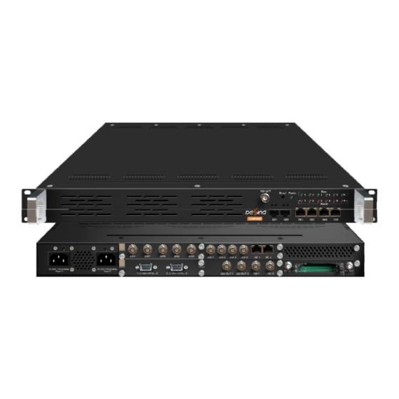
DHP400 Head-end Processor User Manual Chapter 2 Physical Presentational Statement 2.1 Appearance and Description Front Panel Illustration 2 3 4 Air Vent ASI output port GE1/GE2 Output: IP signal output, SFP connector Reset: Reset webmaster IP address, recover it to default IP address... - Page 6 DHP400 Head-end Processor User Manual Module Illustration: DX504 4 ASI/IP Multiplexing Module DX505 5 ASI Multiplexing Module DX214 4 CVBS Encoding Module DX202A 2 HDMI Encoding/Transcoding Module DX202A-D 2 SDI Encoding/Transcoding Module DX224 4 HDMI Encoding Module...
- Page 7 DHP400 Head-end Processor User Manual DX202 2 IP Transcoding Module DX702 2 HD-SDI Decoding Module DX316/332 16/32 QAM Modulating Module DX308T 8 DVB-T Modulating Module DX308C 8 ATSC Modulating Module DX306I 6 ISDB-Tb Modulating Module DX902 2 Tuner(DVB-S/S2) Descrambling Module...
-
Page 8: Chapter 3 Installation Guide
DHP400 Head-end Processor User Manual Chapter 3 Installation Guide 3.1 Acquisition Check When user opens the package of the device, it is necessary to check items according to packing list. Normally it should include the following items: DHP400 Head-end processor ... - Page 9 DHP400 Head-end Processor User Manual 3.2.2 Environment Requirement Item Requirement When user installs machine frame array in one machine hall, the Machine Hall Space distance between 2 rows of machine frames should be 1.2~1.5m and the distance against wall should be no less than 0.8m.
-
Page 10: Wire's Connection
DHP400 Head-end Processor User Manual All function modules’ good grounding is the basis of reliability and stability of devices. Also, they are the most important guarantee of lightning arresting and interference rejection. Therefore, the system must follow this rule. - Page 11 When the device adopts united way, the grounding resistance should be smaller than 1Ω. Caution: Before connecting power cord to DHP400 head-end proccesor, user should set the power switch to “OFF”. 3.3.2 Signal and NMS Cable Connection The signal connections include the connection of input signal cable and the connection of output signal cable.
-
Page 12: Chapter 4 Web Nms Management
DHP400 Head-end Processor User Manual Chapter 4 Web NMS Management This device does not support the LCD operation, and the modification can only be operated under Web NMS. 4.1 Login The factory default IP address is 192.168.000.136 and users can connect the device and web NMS through this IP address. -
Page 13: Operation
DHP400 Head-end Processor User Manual 10 4.2 Operation 4.2.1 Summary When we confirm the login, it displays the SUMMARY interface as Figure-2. Indicators—Green User can click any item here to light indicates the TS enter the corresponding is normal, which... -
Page 14: Dhp400 Head-End Processor User Manual
DHP400 Head-end Processor User Manual 11 Users click here to set the corresponding parameters Figure-3 Users click “Batch” to set the IP input and general mux parameters for this module, and it display the interface as below (Figure-4):... -
Page 15: Dhp400 Head-End Processor User Manual
DHP400 Head-end Processor User Manual 12 Figure-4 Users click “Mux” to set the mux parameters, and it display the interface as below (Figure-5): Note: “module export” indicates that the TS will be exported to main board, and “Connector” indicate that the TS from main board after processing. -
Page 16: Figure
DHP400 Head-end Processor User Manual 13 Select mux-output channel, there are 5 options: CH 1/2/3/4 and 1 module export Users can select the programs input port Input Area Output Area Programs from ASI1-4 and Programs which connector output CH 1 received... -
Page 17: Dhp400 Head-End Processor User Manual
DHP400 Head-end Processor User Manual 14 Figure-6 From the menu on up side of the webpage, clicking “General”, user can set the parameters of the each output carriers. It displays the interface as Figure-7. Figure-7 From the menu on up side of the webpage, clicking “PID Pass”, it displays the interface where to... -
Page 18: Figure
DHP400 Head-end Processor User Manual 15 Click this button to generate more rows to add PIDs. Figure-8 DX504 also supports TS output with 4 channels through the two GE port. Each channel for GE1 and GE2 has independent IP address and IP number. -
Page 19: Figure
DHP400 Head-end Processor User Manual 16 Figure-10 2. DX505 5 ASI Multiplexing Module DX505 module has 5 ASI bi-direction port for input and output. Users click “In-Out” to set the 5ASI direction and it display the interface as below (Figure-11):... - Page 20 DHP400 Head-end Processor User Manual 17 “Connector” indicate that the TS from main board after processing. Select mux-output channel, there are 5 options: ASI 1/2/3/4/5 and 1 module Output Area Input Area Programs which Programs from ASI1-4 output CH 1 received...
-
Page 21: The Each Output Carriers. It Displays The Interface As Figure
DHP400 Head-end Processor User Manual 18 Figure-13 From the menu on up side of the webpage, clicking “General”, user can set the parameters of the each output carriers. It displays the interface as Figure-14. Figure-14 From the menu on up side of the webpage, clicking “PID Pass”, it displays the interface where to... - Page 22 DHP400 Head-end Processor User Manual 19 Click this button to generate more rows to add PIDs. Figure-15 From the menu on up side of the webpage, clicking “PID Monitor”, it displays the interface where to set the PID parameters. (Figure-16) Figure-16 From the menu on up side of the webpage, clicking “System”, it displays the interface...
- Page 23 DHP400 Head-end Processor User Manual 20 Figure-17 3. DX214 4 CVBS Encoding Module DX214 has 24 CVBS input interfaces and 24 pairs of unbalanced analogue stereo audio input interfaces, Users click “Encoding CH1-CH4” to set the encoding parameters and it display the interface as below (Figure-18): Each channel’s information...
- Page 24 DHP400 Head-end Processor User Manual 21 interface as below (Figure-19): Figure-19 4. DX202A 2 HDMI Decoding Module DX202A module has 2 HDMI input, and this module can be used as transcoding module or encoding module. Users click “Encoder/Transcoder 1/2” to set the parameters and it display the...
- Page 25 DHP400 Head-end Processor User Manual 22 Figure-21 5. DX202A-D 2 SDI Encoding/Transcoding Module DX202A-D module has 2 SDI input, and this module can be used as transcoding module or encoding module. Users click “Encoder/Transcoder 1/2” to set the parameters and it display the...
- Page 26 DHP400 Head-end Processor User Manual 23 From the menu on up side of the webpage, clicking “System”, it displays the interface (Figure-23) where users can check and set DX202A-D module’s system information. Figure-23 6. DX224 4 HDMI Encoding Module DX224 support 4 HDMI input channel, Users click “Tuner1-2” to configure the input tuner parameters to receive satellite signals and it display the interface as below (Figure-24): Each channel’s information...
- Page 27 DHP400 Head-end Processor User Manual 24 Figure-25 7. DX202 2 IP Transcoding Module DX202 module is a transcoding module which supports video and audio transcoding, and because of DX202 without input or output port, it should be used combine with other module. Users click “CH1/CH2”...
- Page 28 DHP400 Head-end Processor User Manual 25 Figure-27 8. DX702 2 HD-SDI Decoding Module DX702 module has 2ASI input and 2 SDI output. DX702 ASI port can be used as input or output port, and users click “In-Out” to select the ASI direction and it display the interface as below...
- Page 29 DHP400 Head-end Processor User Manual 26 Users click “Mux” to set the mux parameters, and it display the interface as below (Figure-29): There are 4 options Input Area Output Area Operation Area Figure-29 Configure ‘Input Area’ and ‘Output Area’ with buttons in ‘Operation Area’. Instructions are as...
-
Page 30: Add The Pids Which Needs Pass Through. (Figure
DHP400 Head-end Processor User Manual 27 Figure-30 From the menu on up side of the webpage, clicking “General”, user can set the ASI output1, ASI output2 and module1 export general parameters of this module. It displays the interface as Figure-31. - Page 31 DHP400 Head-end Processor User Manual 28 Click this button to generate more rows to add PIDs. Figure-32 DX702 module supports to decode up to 2 programs to output simultaneously through the SDI ports. From the menu on up side of the webpage, clicking “Decoder”, it displays the interface where users can configure the Video/Audio output parameters respectively (Figure-33).
- Page 32 DHP400 Head-end Processor User Manual 29 Click button at last to confirm. Wait for a moment until the status light turns to green. From the menu on up side of the webpage, clicking “System”, it displays the interface (Figure-34) where users can check and set DX702 module’s system information.
- Page 33 DHP400 Head-end Processor User Manual 30 Figure-35 From the menu on up side of the webpage, clicking “General”, it displays the interface where users can set parameters for each output channel. (Figure-36) Figure-36 Users click the interface is display as below, and click to apply the modified parameters.(Figure-37)
- Page 34 DHP400 Head-end Processor User Manual 31 Figure-37 From the menu on up side of the webpage, clicking “PID Pass”, it displays the interface where to add the PIDs which need pass through. (Figure-38) Figure-38 DX306I supports TS to output in IP (6*MPTS) format through the DATA port.
- Page 35 DHP400 Head-end Processor User Manual 32 Click to set all channels RF output parameters Click to set each channel RF output parameters Figure-40 From the menu on up side of the webpage, clicking “System”, it displays the interface (Figure-41) where users can check and set DX306I module’s system information.
- Page 36 DHP400 Head-end Processor User Manual 33 Figure-41 13. DX902 2 Tuner(DVB-S/S2) Descrambling Module 14. DX912 2 Tuner(DVB-C) Descrambling Module DX902/912 module has 2 DVB-S/S2/DVB-C tuner inputs. Users click “Tuner1-2” to configure the input tuner parameters to receive satellite signals and it display the interface as below...
- Page 37 DHP400 Head-end Processor User Manual 34 Card Selection Area Figure-43 One CI card can be applied to descramble programs from the 2 Tuner input signal sources. ‘Skip CI card’ means to skip the card which is used for FTA stream.
- Page 38 DHP400 Head-end Processor User Manual 35 Program list from the channel selected ‘Input TS Mode’ Figure-44 Check the program(s) to be descrambled and click button to start descrambling the checked program(s). The program quantity to be descrambled will depend on the CAM/CI performance you apply to.
- Page 39 DHP400 Head-end Processor User Manual 36 Figure-45 From the menu on up side of the webpage, clicking “Mux”, it displays the interface where users can choose the programs from 2 Tuner and connect input to Mux out. (Figure-46) Output Area...
- Page 40 DHP400 Head-end Processor User Manual 37 To refresh the input program information To refresh the output program information Select one input program first and click this button to transfer the selected program to the right box to output. Similarly, user can cancel the multiplexed programs from the right box.
- Page 41 DHP400 Head-end Processor User Manual 38 Click this button to generate more rows to add PIDs. Figure-48 From the menu on up side of the webpage, clicking “General”, user can set the parameters of the each output carriers. It displays the interface as Figure-49.
- Page 42 DHP400 Head-end Processor User Manual 39 Figure-50 15. DX904 4 FTA Tuner(DVB-S/S2) Module 16. DX914 4 FTA Tuner(DVB-C) Module 17. DX944 4 FTA Tuner(DVB-T/T2) Module DX904/914/944 module has 4 DVB-S/S2/DVB-C/DVB-T/T2 tuner inputs. Users click “Tuner1-4” to set the RF parameters and it display the interface as below (Figure-51):...
- Page 43 DHP400 Head-end Processor User Manual 40 Because of DX904/914/944 module without output port, it should be used combine with other module. Users click “Mux” to set the mux parameters, and it display the interface as below (Figure-52): Output Area Input Area...
- Page 44 DHP400 Head-end Processor User Manual 41 : To enable/disable the PID remapping To refresh the input program information To refresh the output program information Select one input program first and click this button to transfer the selected program to the right box to output.
- Page 45 DHP400 Head-end Processor User Manual 42 Click this button to generate more rows to add PIDs. Figure-54 From the menu on up side of the webpage, clicking “General”, user can set the general parameters of this module. It displays the interface as Figure-55.
- Page 46 From the menu on left side of the webpage, clicking “Stream Connect”, user can select programs from each module and mux to connector X. DHP400 support 6 module output, 8 MPTS (only output via GE2) and 512 SPTS (only output via GE1), and ASI output programs are same as MPTS2.It displays the interface as Figure-57.
- Page 47 DHP400 Head-end Processor User Manual 44 Configure ‘Input Area’ and ‘Output Area’ with buttons in ‘Operation Area’. Instructions are as below: : To enable/disable the PID remapping To refresh the input program information To refresh the output program information Select one input program first and click this button to transfer the selected program to the right box to output.
- Page 48 Note: users can only click “Stream Select ” to check the stream connect status when stay on “General” web page.( Figure-60) Figure-60 Parameters → IP Stream: DHP400 supports TS to output in IP format through the DATA port. Click ‘IP Stream’, it will display the interface as Figure-61 where to set IP out parameters.
- Page 49 DHP400 Head-end Processor User Manual 46 Figure-61 Parameters → General: users can only click “General ” to debug module.( Figure-62) Figure-62 System → Network: Click ‘Network’, it will display the interface as Figure-63 where to set network parameters.
- Page 50 DHP400 Head-end Processor User Manual 47 Figure-63 System → Password: From the menu on left side of the webpage, clicking “Password”, it will display the screen as Figure-64 where to set the login account and password for the web NMS.
- Page 51 DHP400 Head-end Processor User Manual 48 Select areas Figure-65 System → Firmware: From the menu on left side of the webpage, clicking “Firmware”, it will display the screen as Figure-66 where to update firmware for the device. Figure-66 System → Log: From the menu on left side of the webpage, clicking “Log”, it will display the screen as...
- Page 52 DHP400 Head-end Processor User Manual 49 Figure-67...
-
Page 53: Chapter 5 Troubleshooting
DHP400 Head-end Processor User Manual 50 Chapter 5 Troubleshooting DEXIN’s ISO9001 quality assurance system has been approved by CQC organization. For guarantee the products’ quality, reliability and stability. All DEXIN products have been passed the testing and inspection before ship out factory. - Page 54 DHP400 Head-end Processor User Manual 51 Any stuff causes circuit short Device in damp environment Device was suffered from physical damage Longtime idle. After switching on and restoring to factory setting, device still cannot work properly.
-
Page 55: Chapter 6 Packing List
DHP400 Head-end Processor User Manual 52 Chapter 6 Packing list DHP400 Head-end processor User’s Manual Power Cord...
Need help?
Do you have a question about the DHP400 and is the answer not in the manual?
Questions and answers