
Subscribe to Our Youtube Channel
Related Manuals for Autarco S2.LAN-BOX

Summary of Contents for Autarco S2.LAN-BOX
- Page 1 Installation manual LAN Monitoring Gateway for Autarco inverters © Autarco Group B.V. IM.S2.LAN-GATEWAY-EN-V1.0...
- Page 2 Product information is subject to change without notice. All trademarks are recognized as the property of their respective owners. If any technical problems occur, please contact us, with the following information in hand. Device Model Serial number of product © Autarco Group B.V. All rights reserved. LAN Monitoring Gateway...
-
Page 3: Table Of Contents
Installation manual Table of contents Introduction Read this first Checklist Interface and connection Mounting gateway Installing the LAN Monitoring Gateway Connection with single inverter Connection with multiple inverters Confirm connection Network setting Connection via Wi-Fi Connection via Ethernet Registration Check connection in MyAutarco Monitoring setup Debug LED indication... -
Page 4: Introduction
1.1 Read this first The main purpose of this user manual is to provide instructions and detailed procedures for installing, operating, maintaining, and troubleshooting the Autarco LAN Monitoring Gateway which is used with the Autarco inverters. To reduce the risk of electrical shock, and to ensure the safe installation and operation of the LAN Monitoring... -
Page 5: Interface And Connection
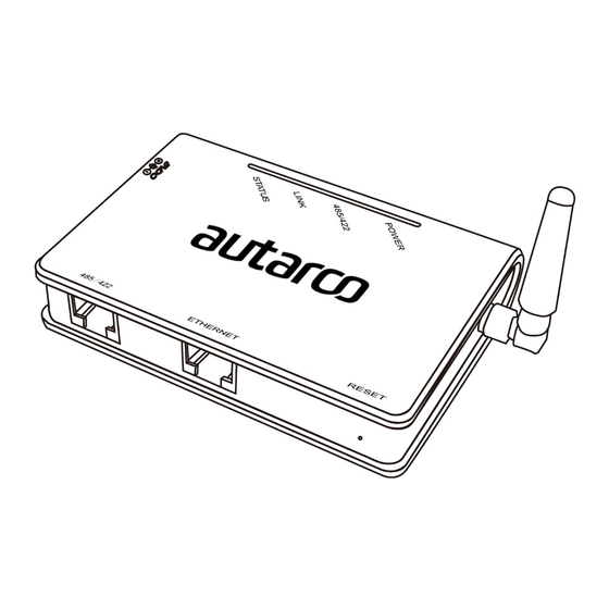
Installation manual 1.3 Interface and connection LEDs Antenna Port Power adapter port RESET Ethernet RS485/422 SN serial number WARNING! When you screw/unscrew or adjust the antenna, please make sure that you only use the metal part of the antenna. Do not hold the plastic part while adjusting otherwise the antenna may be damaged. -
Page 6: Installing The Lan Monitoring Gateway
2. Installing the LAN Monitoring Gateway WARNING! Power supply of inverters must be cut off before connection. Make sure that all connections are completed, then power the gateway and inverters, otherwise personal injury or equipment damage may be caused. 2.1 Connection with single inverter Connection to local router via WiFi Connect inverter to gateway with monitoring cable and connect gateway to power supply with power adapter. -
Page 7: Connection With Multiple Inverters
Installation manual 2.2 Connection with multiple inverters 1. Parallel connect multiple inverters with network cables. 2. Connect first inverter to gateway with network cable. 3. Set different address for each inverter. For example, when connecting three inverters, the address of first inverter must be set as "01", the second must be set as "02", and the third must be set as "03"... -
Page 8: Confirm Connection
2.3 Confirm connection When all connections are finished and with the power on for about 1 minute, check the 4 LEDs. If POWER and STATUS are permanently on, and LINK and 485/422 are permanently on or flashing, connections are successful. If any problems, please refer to Chapter 5 ‘Debug’. -
Page 9: Network Setting
Installation manual 3. Network setting The LAN Monitoring Gateway can transfer information to the router via either Wi-Fi or Ethernet, users may choose the appropriate method accordingly. 3.1 Connection via Wi-Fi WARNING! The setting hereinafter is operated with Window XP for reference only. If other operating systems are used, please follow the corresponding procedures. - Page 10 Step 3: Set WiFi connection to the gateway 1. Open wireless network connection and click View Wireless Networks. 2. Select wireless network of the data logging module, no passwords required as default. The network name consists of AP and the serial number of the product. Then click Connect. LAN Monitoring Gateway...
- Page 11 Step 4: Set parameters of gateway a. Open a web browser, and enter 10.10.100.254, then fill in username and password, both of which are admin as default. Autarco recommends to change the access settings after installation for security reasons. WARNING! Supported browsers: Internet Explorer 8+, Google Chrome 15+, Firefox 10+...
- Page 12 b. In the configuration interface of gateway, you can view general information of the gateway Follow the setup wizard to start quick setting. 1. Click Wizard to start. 2. Click Start to continue. LAN Monitoring Gateway...
- Page 13 Installation manual 3. Select Wireless Connection, and click Next. 4. Click Refresh to search available wireless networks, or add it manually. 5. Select the wireless network you need to connect, then click Next. IM.S2.LAN-GATEWAY-EN-V1.0...
- Page 14 WARNING! If the signal strength (RSSI) of the selected network is <20%, the connection can be unstable, please adjust the antenna. Decrease distance to the router or use a repeater to enhance the signal. 6. Enter the password for the selected network, then click Next. 7.
- Page 15 Installation manual 8. If setting is successful, the following page will display. Click OK to restart. 9. If restart is successful, the following page will display. IM.S2.LAN-GATEWAY-EN-V1.0...
-
Page 16: Connection Via Ethernet
Open a web browser and enter the assigned IP address to get access to the configuration interface of the gateway. Fill in username and password, both of which are admin as default. Autarco recommends to change the access settings after installation for higher security. - Page 17 Installation manual Follow the setup wizard to start quick setting. 1. Click Wizard to start. 2. Click Start to continue. IM.S2.LAN-GATEWAY-EN-V1.0...
- Page 18 3. Select Cable Connection, and you can choose to enable or disable the wireless function, then click Next. 4. Select Enable to obtain an IP address automatically, then click Next. LAN Monitoring Gateway...
- Page 19 Installation manual 5. If setting is successful, the following page will display. Click OK to restart. 6. If restart is successful, the following page will display. WARNING! After setting is completed, if STATUS is permanently on after about 30 seconds, and the 4 LEDs are all on after 2-5 minutes, the connection is successful.
-
Page 20: Registration
4.2 Monitoring setup In order to register your LAN Monitoring Gateway in MyAutarco, and to allocate it to a registered PV system, send an e-mail to support@autarco.com, holding the following information: • LAN Monitoring Gateway: Serial ID •... -
Page 21: Debug
Installation manual 5. Debug 5.1 LED indication LEDs Status Meaning Power is normal POWER Power is abnormal Connection between gateway and inverter is normal 485\422 Flashing Data is transmitting between gateway and inverter Connection between gateway and inverter is abnormal STATUS Off LINK Flashing Connecting STATUS On LINK On Connection of gateway is normal... -
Page 22: Trouble Shooting
5.2 Trouble Shooting Phenomenon Meaning Solutions No power supply Connect power supply and ensure good contacts. Connection with inverter is Check the connection cable, and ensure that the cable abnormal order comply with T568B. Ensure the stability of RJ-45 Ensure that inverter is working under normal condition Flashing In AP mode Set network...
Need help?
Do you have a question about the S2.LAN-BOX and is the answer not in the manual?
Questions and answers