Table of Contents
Advertisement
Quick Links
PB330 and PB430 PrecisionBrew
Model PB-330
Safety Information..................2
Installation...............................3
Start up ....................................4
Operation ................................5
Adjustments ............................5
Control Features......................6
Programming ..........................7
Thank you for purchasing this quality brewer. For your safety and the safety of others, read all warnings and the
operator manual before installing or using the product. Properly instruct all operators. Keep training records. For
future reference, record serial number here:
Grindmaster-Cecilware
4003 Collins Lane, Louisville, KY 40245 USA
Phone: 502.425.4776 Toll Free: 800.695.4500
Fax: 502.425.4664
Web: gmcw.com Email: info@gmcw.com
©2016 Grindmaster-Cecilware
Printed in USA
Digital Shuttle
™
Model PBVSA-330
Table of Contents
Cleaning.................................13
Maintenance .........................14
Special Control Functions .....14
Troubleshooting Guide.........16
Parts Diagram and List..........22
Wiring Diagram.....................29
Thermistor Chart ...................39
Operator Manual
Model PBIC-430
Grindmaster-Cecilware
industry's BEST warranty. Visit gmcw.com
for warranty terms and conditions.
Brewers
®
provides
the
0516 Form # AM-346-04
Part # 390-00065
Advertisement
Table of Contents

Summary of Contents for Grindmaster Cecilware American Metal Ware PrecisionBrew Digital Shuttle PB330
-
Page 1: Table Of Contents
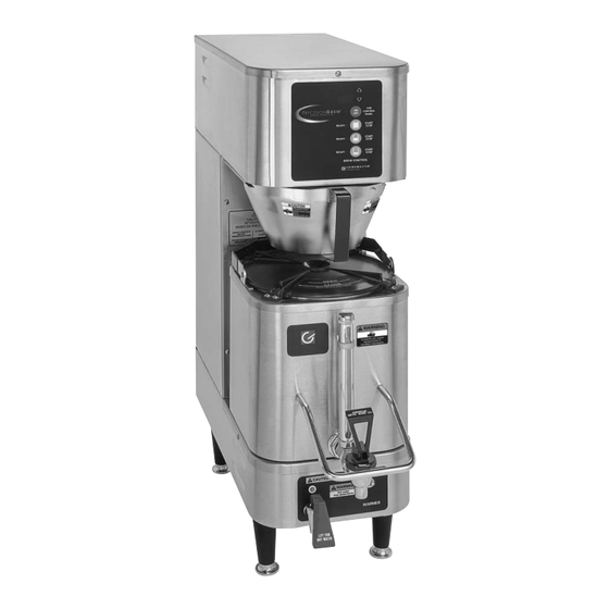
Operator Manual PB330 and PB430 PrecisionBrew Digital Shuttle Brewers ™ ® Model PB-330 Model PBIC-430 Model PBVSA-330 Table of Contents Safety Information....2 Cleaning.........13 Installation.......3 Maintenance ......14 Start up ........4 Special Control Functions ..14 Operation ........5 Troubleshooting Guide..16 Adjustments ......5 Parts Diagram and List..22 Control Features......6 Wiring Diagram.....29 Programming ......7... -
Page 2: Safety Information
Safety Information Important Safety Information This is the safety alert symbol. It is used to alert you to potential personal injury hazards. Obey all safety messages that follow this symbol to avoid possible injury or death. For your safety and the safety of others, read all warnings and the operator manual before installing or using the product. -
Page 3: Installation
Installation Unpacking Instructions 6. Make sure brewer is unplugged. Connect the water line to the brewer with the hose connector. Carefully unpack the machine and inspect immediately 7. Install a shut-off valve near the brewer. for shipping damage. The packaging may contain un- 8. -
Page 4: Start Up
Installation (continued) 4. Standard connection is 1 phase 3 wire. Connect the connect the white wire from the terminal block to the two lines to L1 and L2 on the terminal block. If the proper tap for the supplied voltage. brewer is wired for three phase, a lug, L3, is See diagram below. -
Page 5: Operation
Operation vacuum Shuttle is 1.6 (6.0L) gallons. CAUTION: HOT LIQUID HAZARD 5. Slide the basket into the brewer making sure the Water used for brewing coffee is very hot. Use spout lines up with the top of the Shuttle. caution when brewing, pouring, or transporting 6. -
Page 6: Control Features
Adjustments (cont.) Temperature Adjustment (continued) WARNING: ELECTRIC SHOCK HAZARD! Dangerous electric voltages are present near adjustable components. All adjustments should be performed by qualified service personnel only. Brew Volume “br” Brew time can be set for each size visually. See Setting Brew Volume Procedure below. Brew time can also be adjusted through the display. -
Page 7: Programming
Programming On twin brewers, the right side, Large portion button (top green button) gives the user access to the global programming parameters of the brewer, such as; Tank Temperature, Energy Savings Mode, Enable/Disable Low Temp No Brew, ON/OFF, Drip Time and Bypass Ratio. After the global parameters are set, the individual portion brew parameters can be set. - Page 8 Programming (continued) By-PASS (Set bypass volume): Choose OFF to 25% Set the amount of bypass desired during brew. If none is desired then set to OFF, otherwise, set the % of brew volume to bypass. CoPY-to-LEFt: Choose YES or no If the same program parameters are desired on same portion size on the left side, then choose YES and the parameters will be copied.
- Page 9 Programming (continued) Table 1 Programming Sequence for Large Left Portion (continued) DRIP TIME DRIP TIME PERCENT OF BREW BYPASS RATIO BREW TIME BREW TIME (.01 TO 6.00) PRE INFUSION DISPLAY PRE INFUSION TIME (OFF TO 2.00) READING ADJUST PRE INFUSION PRE INFUSION OFF TIME (.05 TO 2.00) PULSE BREW...
- Page 10 Programming (continued) Table 1 Programming Sequence for Large Left Portion (continued) PRE INFUSION PRE INFUSION OFF TIME (.05 TO 2.00) PULSE BREW # OF PULSES (OFF, 1 - 10) PULSE ON PULSE ON TIME (0:05-2:00) PULSE OFF PULSE OFF TIME (0:05-2:00) Table 2 Programming Sequence for Medium Portion PRESS-AND-HOLD UP &...
- Page 11 Programming (continued) Table 2 Programming Sequence for Medium Portion (continued) PULSE BREW # OF PULSES (OFF, 1 - 10) PULSE ON PULSE ON TIME (0:05-2:00) PULSE OFF PULSE OFF TIME (0:05-2:00) BY-PASS OFF TO .25 PERCENT COPY TO LEFT PB330 & PB430 Shuttle Brewers American Metal Ware ®...
- Page 12 Programming (continued) Table 3 Programming Sequence for Small Portion PRESS-AND-HOLD UP & DOWN ARROWS FOR 5 SECONDS. DISPLAY WILL READ AS FOLLOWS: DISPLAY READING ADJUST ADVANCE BREW TIME BREW TIME (.01 TO 6.00) PRE INFUSION PRE INFUSION TIME (OFF TO 2.00) PRE INFUSION PRE INFUSION OFF TIME (.05 TO 2.00)
-
Page 13: Cleaning
Cleaning CAUTION: BURN HAZARD 10. Clean the warmer and bottom of Shuttle surfaces. These surfaces must be clean for proper heat Hot liquids and surfaces are present in this transfer. equipment. To avoid burns, use caution when 11. Polish the exterior of the brewer with stainless cleaning. -
Page 14: Maintenance
Maintenance 10 Pin Version 2 Pin Version CAUTION: BURN HAZARD UNLOCKED UNLOCKED Water in tank is very hot. Draining of tank should be performed by a qualified service technician. Use caution when draining tank. Accidental spills may result in severe burns. LOCK LOCK To Drain the Water Tank... - Page 15 Special Control Functions (continued) Step Function Operation Description LED Test All LEDs ON Verify that all LEDs turn on. Firmware Version Display firmware version Shows the software version of the control. Date Code Not used Not used EEPROM Version Not used Not used Non Resetable Unit Scroll non-resetable unit counter Shows the total number of brews made by...
-
Page 16: Troubleshooting Guide
Troubleshooting Guide WARNING: To reduce the risk of electrical shock, unplug the power cord before repairing or replacing any internal components of the unit. Before any attempt to replace a component, be sure to check all electrical connections for proper contact. Only a qualified service technician should perform electrical and mechanical adjustments or repairs. - Page 17 Troubleshooting Guide (continued) WARNING: To reduce the risk of electrical shock, unplug the power cord before repairing or replacing any internal components of the unit. Before any attempt to replace a component, be sure to check all electrical connections for proper contact. Only a qualified service technician should perform electrical and mechanical adjustments or repairs.
- Page 18 Troubleshooting Guide (continued) WARNING: To reduce the risk of electrical shock, unplug the power cord before repairing or replacing any internal components of the unit. Before any attempt to replace a component, be sure to check all electrical connections for proper contact. Only a qualified service technician should perform electrical and mechanical adjustments or repairs.
- Page 19 Troubleshooting Guide (continued) WARNING: To reduce the risk of electrical shock, unplug the power cord before repairing or replacing any internal components of the unit. Before any attempt to replace a component, be sure to check all electrical connections for proper contact. Only a qualified service technician should perform electrical and mechanical adjustments or repairs.
- Page 20 Troubleshooting Guide (continued) WARNING: To reduce the risk of electrical shock, unplug the power cord before repairing or replacing any internal components of the unit. Before any attempt to replace a component, be sure to check all electrical connections for proper contact. Only a qualified service technician should perform electrical and mechanical adjustments or repairs.
- Page 21 Troubleshooting Guide (continued) WARNING: To reduce the risk of electrical shock, unplug the power cord before repairing or replacing any internal components of the unit. Before any attempt to replace a component, be sure to check all electrical connections for proper contact. Only a qualified service technician should perform electrical and mechanical adjustments or repairs.
-
Page 22: Parts Diagram And List
Parts Diagram and List Front View Lower Warmer (PB-430 pictured) American Metal Ware PB330 & PB430 Shuttle Brewers ®... - Page 23 Parts Diagram and List (continued) Top View Tank Lid (3 Heater Model shown) PB330 & PB430 Shuttle Brewers American Metal Ware ®...
- Page 24 Parts Diagram and List (continued) Models PB-330, PB-430, PBVSA-330, PBVSA-430, PBIC-330, PBIC-430 ITEM DESCRIPTION PART # Reference Front View Picture: Controller PB A530-066 (older version A530-059) Relay, Heater* A71450 Water Inlet Valve 24 VAC A71683 Terminal Block A531-035 Spray Head APT400-105 (older version A400-010) Orifice Bypass A518-053 (older version A5518-045)
- Page 25 Parts Diagram and List (continued) Top View Item Part # Description A537-053 FAUCET MODEL ES A522078 SHANK W/ CHROME BONNET A718-018 GAUGE ASSEMBLY A725-092 KIT, SHUTTLE LID SS SHUTTLE COVER A713-027 (not shown)* A548-142 LID RETAINING CLIP A548-140 LID STOPPER W/ O-RING A61365 * S.S.
- Page 26 Parts Diagram and List (continued) Model VS-1.5 Vacuum Shuttle Parts List VS-1.5S ITEM NO. Title PART NUMBER VS-1.5S/QTY. TITLE Stand Body A548-157 Tray for Stand A548-159 Vacuum Shuttle VS-1.5 Stand Base A548-158 Tray Top A517-018 Self-Tapping Screw .5" A539-217 Rubber Foot A548-161 Plastic Insert A548-162...
- Page 27 Parts Diagram and List (continued) Model VS-1.5 Vacuum Shuttle Parts List VS-S ITEM NO. Title PART NUMBER VS-S/QTY. TITLE Stand Body A548-157 Tray for Stand A548-159 Stand Base A548-158 Tray Top A517-018 Stand, Top Plate A517-019 NUT M4 W Nylon Insert A540-237 Self-Tapping Screw .5"...
- Page 28 Parts Diagram and List (continued) Control Board all PrecisionBrew™ V2.0 models Refers to software version number. Subject to change. American Metal Ware PB330 & PB430 Shuttle Brewers ®...
-
Page 29: Wiring Diagram
Wiring Diagram Precision Brew 330 Series - Models APB-330V2, APBVSA-330V2, and APBIC-330V2 PB330 & PB430 Shuttle Brewers American Metal Ware ®... - Page 30 Wiring Diagram (continued) Precision Brew 430 Series Models APB-430V2, APBVSA-430V2, and APBIC-430V2 American Metal Ware PB330 & PB430 Shuttle Brewers ®...
- Page 31 Wiring Diagram (continued) APB-330V2E230, APBVSA-330V2E230, APBIC-330V2E230 Brewers PB330 & PB430 Shuttle Brewers American Metal Ware ®...
- Page 32 Wiring Diagram (continued) APB-430V2E230, APBVSA-430V2E230, APBIC-430V2E230 (Single or Three Phase Models) American Metal Ware PB330 & PB430 Shuttle Brewers ®...
- Page 33 Wiring Diagram (continued) Precision Brew 330 Series 120/208V, 120/240V Models APB-330V2, APBVSA-330V2, and APBIC-330V2 PB330 & PB430 Shuttle Brewers American Metal Ware ®...
- Page 34 Wiring Diagram (continued) Precision Brew 430 Series 120/208 or 120/240V Models APB-430V2, APBVSA-430V2, and APBIC-430V2 American Metal Ware PB330 & PB430 Shuttle Brewers ®...
- Page 35 Wiring Diagram (continued) 230V, 208V, or 240V without Neutral Models APB-330V2, APBVSA-330V2, APBIC-330V2, APB- 30V2E230, APBVSA-330V2E230, APBIC-330V2E230 PB330 & PB430 Shuttle Brewers American Metal Ware ®...
- Page 36 Wiring Diagram (continued) 230V, 208V, or 240V without Neutral Models APB-430V2, APBVSA-430V2, APBIC-430V2, APB- 30V2E230, APBVSA-430V2E230, and APBIC-430V2E230 American Metal Ware PB330 & PB430 Shuttle Brewers ®...
- Page 37 Wiring Diagram (continued) Heater Configuration (1 Heater) PB330 & PB430 Shuttle Brewers American Metal Ware ®...
- Page 38 Wiring Diagram (continued) Heater Configuration (3 Heater) American Metal Ware PB330 & PB430 Shuttle Brewers ®...
-
Page 39: Thermistor Chart
Thermistor Chart Resistance chart showing the ohm value of the thermistor at the appropriate temperature. THERMISTOR CURVE FOR PART # A725-097 °C °F RESISTANCE (OHMS) °C °F RESISTANCE (OHMS) 16325 1244 12697 1041 9951 7856 6246 5000 4028 3266 2663 2185 1802 1493 PB330 &... - Page 40 Grindmaster-Cecilware 4003 Collins Lane, Louisville, KY 40245 USA Phone: 502.425.4776 Toll Free: 800.695.4500 Fax: 502.425.4664 Web: gmcw.com Email: info@gmcw.com 0516 Form # AM-346-04 ©2016 Grindmaster-Cecilware Part # 390-00065 Printed in USA...
Need help?
Do you have a question about the American Metal Ware PrecisionBrew Digital Shuttle PB330 and is the answer not in the manual?
Questions and answers