
Subscribe to Our Youtube Channel
Related Manuals for Bently Nevada Ranger Pro 70M303

Summary of Contents for Bently Nevada Ranger Pro 70M303
- Page 1 Ranger Pro Wireless Condition Monitoring User Guide Bently Nevada Machinery Condition Monitoring Document: 125M6113 Rev. C...
- Page 2 Copyright 2019 Baker Hughes, a GE company, LLC ("BHGE") All rights reserved. Bently Nevada, Orbit Logo and Ranger are registered trademarks of BHGE in the United States and other countries. All product and company names are trademarks of their respective holders. Use of the trademark does not imply any affiliation with or endorsement by the respective holders.
-
Page 3: Table Of Contents
Ranger Pro Wireless Condition Monitoring User Guide Contents 1. General Safety 1.1 Receiving Inspection 1.2 Handling and Storing Considerations 1.3 Personal Safety Warnings 1.4 Safe Disposal 2. Hardware 2.1 Intended Use 2.2 Compliance Information 2.3 Description 2.4 System Components Required 3. -
Page 4: General Safety
1.1 Receiving Inspection Visually inspect the monitor for obvious shipping damage. If you detect shipping damage, file a claim with the carrier and submit a copy to Bently Nevada. Include all model numbers and serial numbers with the claim. 1.2 Handling and Storing Considerations Proper handling of components, best practices for system installation, and diligent inspection procedures for the system will prolong the service life of the system. -
Page 5: Personal Safety Warnings
Ranger Pro Wireless Condition Monitoring User Guide 1.3 Personal Safety Warnings Labels and markings are provided on the monitor to guide the system integrator in the processes of choosing appropriate interface equipment, determining safe use conditions, and identifying recommended installation procedures. The format of these markings are governed by the standards that dictate safe use and environmental compliance in a variety of regions and regulated settings. - Page 6 Ranger Pro Wireless Condition Monitoring User Guide Hazardous Environment WARNING HAZARDOUS ENVIRONMENT Risk of explosive atmosphere. De-energize all relays and connections before placement or removal. Take precautionary measures to avoid electrostatic potential, especially on plastic components. Installations and maintenance tasks performed in potentially hazardous areas must be performed only after the area has been verified to be free of hazardous materials, atmospheres, and conditions.
- Page 7 Ranger Pro Wireless Condition Monitoring User Guide Lithium Batteries WARNING USE ONLY ONE OF THE FOLLOWING BATTERIES Xeno Energy XL-205F, Tadiran TL-5930, Tadiran SL-2780. Don’t use a device with a damaged e-module, O-rings, sensor module, or battery. Using a damaged battery may further damage the device, cause it to fail, or in hazardous locations cause other unintended consequences.
-
Page 8: Safe Disposal
Ranger Pro Wireless Condition Monitoring User Guide 1.4 Safe Disposal Replacing Device and Failure Analysis Visit Bently.com to initiate the process for returning parts under warranty and request failure analysis. Hazardous Materials This device does not use hazardous materials outlined by RoHS or battery directive statutes. These regulations confirm that lead, mercury, cadmium, hexavalent chromium, polybrominated biphenyls, polybrominated diphenyl ether, and battery related materials such as lithium are limited to no more than trace amounts within the system. -
Page 9: Hardware
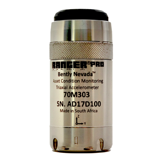
Calculated from the acceleration waveform and the overall value is Velocity Overall calculated over a 2.5 second duration. There are three versions of the device: Ranger Pro 70M303 Detects velocity and acceleration in three axis (X, Y, and Z) and tri-axial sensor measures surface temperature. -
Page 10: System Components Required
Ranger Pro configuration software (121M7997, available from Bently Nevada technical support). Spot facing tool, if required. (Not provided by Bently Nevada.) Torque wrench with ¼ inch drive, capable of tightening devices in the 5-7 Nm (44 to 62 in lb) range. (Not provided by Bently Nevada.) 10/51 125M6113 Rev. - Page 11 Ranger Pro sensors and repeaters. If you use the wrong battery, you can negatively affect device performance, produce inaccurate readings, and void the Ranger Pro warranty. You can purchase approved batteries from Bently Nevada or third-party suppliers. For details and ordering information, see the Ranger Pro Datasheet (document 125M5237).
- Page 12 Ranger Pro Wireless Condition Monitoring User Guide Setup Overview The Ranger Pro operates on the ISA100.11a wireless network protocol. To add Ranger Pro sensors to your network, complete these steps: 1. Survey your installation location. 2. Decide where to install Ranger Pro sensors and identify mounting points. 3.
-
Page 13: Network Design
Ranger Pro Wireless Condition Monitoring User Guide 3. Network Design Ranger Pro sensors operate on the 2.4 GHz band on ISA100.11a wireless networks. To enhance security, the sensors use 128-bit AES encrypted packets. 3.1 Consider Sensor Range A sensor can transmit data up to 150 meters (164 yards) to an access point when unimpeded by environmental influences. -
Page 14: Choose Network Topology
Ranger Pro Wireless Condition Monitoring User Guide Avoid using Ranger Pro devices as both sensors and repeaters. Using a sensor as a router can reduce battery life to 18 to 24 months. Minimize the number of Ranger Pro devices routed through Ranger Pro Repeaters. Avoid connecting more than eight devices through a single Ranger Pro Repeater, or more than five devices through a sensor with router enabled. -
Page 15: Plan Device Placement
Ranger Pro Wireless Condition Monitoring User Guide 3.4 Plan Device Placement Installing and configuring ISA100.11a wireless networks is beyond the scope of this user guide. For details, refer to your vendor's wireless network documentation. Obtain or develop an accurately scaled site plan detailing the placement of the machinery you need to monitor, including architectural details like walls and pillars. - Page 16 Ranger Pro Wireless Condition Monitoring User Guide Place access points in locations where as many sensors as possible can connect directly to each access point. We recommend that you don't exceed 40 devices per access point. Where possible, minimize the distance from the access point to the furthest Ranger Pro device.
-
Page 17: Installation And Configuration
Ranger Pro Wireless Condition Monitoring User Guide 4. Installation and Configuration 4.1 Install Battery We recommend that you install batteries in Ranger Pro devices in an indoors equipment room or a similar environment. Do not replace batteries in a hazardous area. Use only approved battery types described in the Ranger Pro Datasheet (document 125M5237) available from www.bently.com. - Page 18 Ranger Pro Wireless Condition Monitoring User Guide 3. Use the battery installation tool to remove the battery retaining ring. Turn the ring counter-clockwise. Use the magnet in the tool to lift the ring from the device case. 4. Inspect the O-rings on the e-module and case to verify they are present, clean, and undamaged.
- Page 19 Ranger Pro Wireless Condition Monitoring User Guide 7. Use the magnetic Ranger Pro battery installation tool to tighten the battery retaining ring. Hand-tighten the ring until it contacts the battery, then torque to 5 N-m (44 in-lb). 8. To avoid damaging the e-module, you must first align the contact pins of the e-module with the contact points in the case.
-
Page 20: Configure Devices
Ranger Pro Wireless Condition Monitoring User Guide 10. Align the e-module retaining ring over the e-module. If needed, hold the sensor in place with your finger. 11. To maintain the device’s IP67 rating, be careful to avoid damaging the O-rings. Turn the e- module retaining ring clockwise two to three turns, and then counter-clockwise about ¼... - Page 21 Ranger Pro Wireless Condition Monitoring User Guide Temperature measurement settings Vibration measurement settings You can configure Ranger Pro devices two ways: ISA Manager Mode Configure one or many sensors over the network using Ranger Pro (Over the air Configuration Software and ISA device manager to configure Ranger Pro Configuration) devices wirelessly...
- Page 22 Ranger Pro Wireless Condition Monitoring User Guide To view provisioned Ranger Pro devices on ISA100 Gateways: 1. Select ISA100 Manager > Sensor View. 2. All provisioned Ranger Pro devices and their status is displayed. 22/51 125M6113 Rev. C...
- Page 23 Ranger Pro Wireless Condition Monitoring User Guide Configure Sensors Over the Network To configure sensors over the network: 1. Open the Ranger Pro configuration application. 2. Select ISA100 Manager > Sensor View. Current devices are displayed. 3. Select a sensor device. Verify that the sensor status in the application footer is Ready. The sensor configuration is displayed in Configuration Manager > Live View.
-
Page 24: Provision Devices
Ranger Pro Wireless Condition Monitoring User Guide Configure Sensors Using a NFC Reader Using the NFC reader on a bare metal surface can cause interference. Insulate the NFC reader from the metal surface by placing a 2.5 cm (1 in.) thick book or similar material under the NFC reader. - Page 25 Ranger Pro Wireless Condition Monitoring User Guide Provision Using the Yokogawa Gateway To provision Ranger Pro devices on a Yokogawa gateway: 1. In the Yokogawa Field Wireless Management Console, open Monitor. 2. Choose Tools > OTA Provisioning Manager. 3. To allow unprovisioned devices to join, select Enable Provisioning Network. Wait for unprovisioned Ranger Pro devices to display in the Provisioning Network list.
-
Page 26: Unprovision Sensors
To provision sensors, you need: Ranger Pro configuration software (available from Bently Nevada technical support). Ranger Pro sensors with batteries installed ... - Page 27 Ranger Pro Wireless Condition Monitoring User Guide 1. Open Honeywell OneWireless Device Manager. 2. Expand the Selection Panel. 3. Select one or more Ranger Pro device(s). 4. In the tool bar, click Channel > Inactivate. The Inactivate Channels dialog box is displayed.
-
Page 28: Reboot The Device
Ranger Pro Wireless Condition Monitoring User Guide 4.5 Reboot the Device Once you insert a battery into a device, an unprovisioned e-module is ready to receive a join key from the network. If it fails to receive a join key, it enters an increasingly long sleep cycle. It periodically wakes from sleep mode to attempt to join the network. - Page 29 Ranger Pro Wireless Condition Monitoring User Guide Spot facing tool 40 mm (1 ½ inches) diameter Steel wire brush Drills and thread-taps Marker pen Medium strength thread locking compound, for example, Loctite Blue 242 Non-curing silicone grease, for example, Dow Corning 4 Electrical Insulating Compound 29/51 125M6113 Rev.
- Page 30 Ranger Pro Wireless Condition Monitoring User Guide Identify Location and Hardware WARNING ELECTROSTATIC CHARGING HAZARD RISK OF PERSONAL INJURY OR EQUIPMENT DAMAGE. Potential electrostatic charging hazard. Before cleaning or inspecting Ranger Pro devices in a potentially hazardous environment, verify that hazardous materials, atmospheres and conditions have been removed.
- Page 31 Ranger Pro Wireless Condition Monitoring User Guide Complete the Mounting Surface To finish the mounting surface: About Using Adhesives 1. Prepare the mounting surface. To prevent devices separating from the machinery they monitor and to obtain The mounting diameter should be a accurate high frequency response, it's minimum of 40mm (1 ½...
- Page 32 Ranger Pro Wireless Condition Monitoring User Guide 4. To improve high frequency response and reduce transverse vibration, apply a very light amount of silicone grease to the base of the device. 5. Attach the device to the machine surface and tighten the stud.
-
Page 33: Verification
Ranger Pro Wireless Condition Monitoring User Guide 5. Verification 5.1 Verify Network Connectivity Ranger Pro devices can send data to an ISA gateway. The data is then sent from the gateway to the user through Modbus and/or the General Client Interface (GCI). To collect data from the GCI, the user must have System 1 and the Ranger Pro plugin installed. -
Page 34: Validate Device Data
Ranger Pro Wireless Condition Monitoring User Guide Move the device or access point Relocating a device or reorienting its axis or orientation relative to the access point as little as 6 cm (2 1/3 inch), or one-half of a 2.4 GHz wavelength, may improve signal strength. Ranger Pro devices are designed for optimal RF propagation when the device's x-axis is in the horizontal plane. - Page 35 Ranger Pro Wireless Condition Monitoring User Guide Static Process Variable Data Process Variable (PV) or direct data is used to trend the overall vibration and temperature. PV data can be sent to System 1 through GCI or through Modbus/OPC and conforms to ISA100, foundation fieldbus standard.
- Page 36 Ranger Pro Wireless Condition Monitoring User Guide Modbus Settings The Ranger Pro sensors publish vibration and temperature (process variable data) values as 32-bit, floating point data. You can output Ranger Pro static data like vibration and temperature using the gateway's Modbus interface. Phase 1 Ranger Pro Devices Devices use firmware version 01.01.06.03 or earlier.
-
Page 37: Maintenance
Ranger Pro Wireless Condition Monitoring User Guide 6. Maintenance The Ranger Pro device needs minimal maintenance. If a device fails, it may be due to a weak battery, environmental damage, or even a blocked wireless connection. 6.1 Monitor Battery Levels To monitor your Ranger Pro device’s battery status, use your network infrastructure software or the NFC reader and the Ranger Pro software. -
Page 38: Clean And Inspect Devices
Ranger Pro Wireless Condition Monitoring User Guide 6.2 Clean and Inspect Devices To clean the exterior of the Ranger Pro devices in potentially hazardous environment, use a damp cloth. Before cleaning or inspecting Ranger Pro devices in a potentially hazardous environment, verify that hazardous materials, atmospheres and conditions have been removed. - Page 39 Ranger Pro Wireless Condition Monitoring User Guide Good The sensor has been detected and is working correctly. Read Fault The sensor identification data could not be read. (Identification) Model The sensor identification data was successfully read but the model is not Unrecognized recognized.
- Page 40 Ranger Pro Wireless Condition Monitoring User Guide Open the Device Before opening the device, remove it from the field and operating environment. To prevent damage to the O-rings, turn the e-module retaining ring counter-clockwise ½ to one turn, and then clockwise about ¼ turn, and repeat until you can remove the retaining ring. If you experience difficulty removing the retaining ring, the e-module may be rotating with the retaining ring.
- Page 41 Ranger Pro Wireless Condition Monitoring User Guide Verify the orange, reverse polarity protection pad is centered and positioned on the inside and at the bottom of the sensor module. 41/51 125M6113 Rev. C...
-
Page 42: Reboot The Sensor
Ranger Pro Wireless Condition Monitoring User Guide Inspect the O-rings The Ranger Pro device uses two O-rings to seal the unit against dust and moisture. The O-rings maintain the device’s IP67 dust and water-resistant rating. Ranger Pro devices use different size O-rings on the sensor body and e-module. Proper installation and lubrication is required to maintain IP67 rating and prevent leaks. -
Page 43: Update Device Firmware
User Guide 6.4 Update Device Firmware You may on rare occasions need to update the sensor firmware. Download firmware updates from Bently Nevada technical support. You can update firmware over-the-air or using the NFC reader. Each method has advantages and disadvantages. - Page 44 Wireless Condition Monitoring device. To update firmware using the Yokogawa Field Wireless Management Console: 1. Download the CF and firmware files from Bently Nevada technical support. 2. Verify that all Ranger Pro devices are provisioned, connected to the network, and joined to the gateway.
- Page 45 a. Select Load CF/DD. TheWindows Open dialog box is displayed. b. Navigate to the Windows directory location of the device compatibility file you previously downloaded from Bently Nevada tech support. Select the capability file matching the device you want to upgrade, as shown below.
- Page 46 Ranger Pro Wireless Condition Monitoring User Guide OID Concentrator 70M300 Repeater 70M301 Single Axis 70M303 Tri-Axis Value Update policy Default Periodic Periodic Publication period Default Stale limit Default Retry mode Default Normal Normal 10. Restart the devices that you changed. Select the Download button. The Error Check dialog box is displayed.
- Page 47 User Guide Upgrade Sensor Firmware Using Honeywell Gateway Before you upgrade the device firmware, obtain the correct device descriptor (DD) file required for each type of Wireless Condition Monitoring device from Bently Nevada technical support. You only need to add a DD file to the gateway once for each device type.
- Page 48 Ranger Pro Wireless Condition Monitoring User Guide Update Sensor Firmware Using the NFC reader Before you update sensor firmware using the NFC reader: Remove each Ranger Pro device from the field. Depending on the number of devices, this can be a manually time-consuming process. ...
- Page 49 Ranger Pro Wireless Condition Monitoring User Guide Troubleshooting Ranger Pro Devices If a Ranger Pro Wireless Sensors fails, it may be due to a weak battery, environmental damage, or even a blocked wireless connection. To identify the status of a Ranger Pro device: 1.
-
Page 50: Update Radio Firmware
Ranger Pro Wireless Condition Monitoring User Guide Temperature Status Messages Status Description Good The sensor temperature has been read successfully. The status message is followed by the maximum and minimum detected temperatures. Fault The sensor temperature could not be read. Vibration Status Messages Status Description... -
Page 51: Harden The System
Ranger Pro Wireless Condition Monitoring User Guide 6.6 Harden the System The security risk to your network when using Ranger Pro devices is like that in any distributed control system or industrial control system. You need to take all reasonable steps to properly secure these devices.
Need help?
Do you have a question about the Ranger Pro 70M303 and is the answer not in the manual?
Questions and answers