
Subscribe to Our Youtube Channel
Related Manuals for 3M FREEDOM 5000


Summary of Contents for 3M FREEDOM 5000
- Page 1 FREEDOM 5000 Universal Analog Toxic Gas Detector Instruction Manual WARNING EAD AND FOLLOW THE ENTIRE CONTENT OF THIS MANUAL PRIOR TO AILURE TO DO SO MAY RESULT IN SERIOUS INJURY OR DEATH 087-0020 REV E...
- Page 2 Freedom 5000 Universal Analog Toxic Gas Detector Instruction Manual © 2018 Scott Safety, SCOTT, the SCOTT SAFETY Logo, Scott Health and Safety, Protégé, Scout, Freedom, Masterdock, are registered and/or unregistered marks of Scott Technologies, Inc. or its affiliates. All rights reserved. No part of this documentation may be reproduced in any form or by any means or used to make any derivative work (such as translation, transformation, or adaptation) without written permission from Scott Safety.
-
Page 3: Table Of Contents
Freedom 5000 Universal Analog Toxic Gas Detector Instruction Manual Table of Contents Important Notices ....................7 Warnings, Cautions, and Notes ................8 General Warnings and Cautions ................9 Warranty ......................10 Contacting Scott Safety ..................10 Approvals ......................12 Acronyms Quick Reference ................13 Introduction ...................... - Page 4 Freedom 5000 Universal Analog Toxic Gas Detector Instruction Manual List of Figures Figure 1. Freedom 5000 with Integral Sensor ..............15 Figure 2 Sensor Operation ....................16 Figure 3 Interface ......................20 Figure 4 Inside View ......................22 Figure 5 Dimensional Drawing (with optional wall mount bracket) ........23 Figure 6 L Mounting Bracket ...................
- Page 5 Freedom 5000 Universal Analog Toxic Gas Detector Instruction Manual List of Tables Table 1 Acronym Quick Reference List ................13 Table 2. Conventional Sensors Part List (Not Rock-Solid) ..........47 Table 3. Rock Solid Sensor Part List ................49 087-0020 REV E...
- Page 6 Revised Sensor Life section; revised Span Calibration Procedure section; added revision table, list of figures, list of tables; removed Sensor Life form Specifications section; added and removed sensors form part list to update to reflect current sensor offerings; removed all references to TYCO; added 3M logo; updated service center contact information.
-
Page 7: Important Notices
Freedom 5000 Universal Analog Toxic Gas Detector Instruction Manual Safety and General Information WARNING ALL INDIVIDUALS WHO HAVE OR WILL HAVE RESPONSIBILITY FOR USING OR TESTING THIS PRODUCT MUST READ AND UNDERSTAND THE CONTENTS OF THIS MANUAL HE PRODUCT WILL PERFORM AS DESIGNED ’... -
Page 8: Warnings, Cautions, And Notes
Freedom 5000 Universal Analog Toxic Gas Detector Instruction Manual Warnings, Cautions, and Notes Throughout this document, warnings, cautions, and notes have been interspersed to draw attention to potentially unsafe, hazardous, or unique situations that require user attention. Each warning, caution, or note is labeled. -
Page 9: General Warnings And Cautions
Freedom 5000 Universal Analog Toxic Gas Detector Instruction Manual General Warnings and Cautions The following list of warnings and cautions pertain to the general use and care of the Freedom 5000. Failure to follow these warnings and cautions may result in death, injury, or poor equipment performance. -
Page 10: Warranty
Instruction Manual Warranty Statement Scott Safety (SCOTT) warrants the FREEDOM 5000 UNIVERSAL ANALOG TOXIC GAS MONITORS (also referred to as THE PRODUCTS) to be free from defects in workmanship and materials for a period of two (2) years from the date of original manufacture by SCOTT. - Page 11 Attn: Alfeo P. Sinogaya Portable & Fixed Gas Flame Detection Scott Safety | Detcon | Oldham | Simtronics | GMI 3M Personal Safety Division, Safety & Graphics Business Group 1 Yishun Avenue 7 | Singapore 768923 Email: asinogaya@scottsafety.com & asinogaya@mmm.com...
-
Page 12: Approvals
Freedom 5000 Universal Analog Toxic Gas Detector Instruction Manual Approvals The Freedom 5000 has been tested and complies with the following directives, standards, or standardized documents: North America CLASS I DIVISION 2 GROUPS A, B, C, D T6; NEMA 4X... -
Page 13: Acronyms Quick Reference
Freedom 5000 Universal Analog Toxic Gas Detector Instruction Manual Acronyms Quick Reference Throughout the duration of this manual, several acronyms are used. Provided in Table 1 is a quick reference chart to quickly identify any acronym that may be unfamiliar to users. -
Page 14: Introduction
Freedom 5000 Universal Analog Toxic Gas Detector Instruction Manual Introduction Unpacking All Freedom™ 5000 items are individually packaged. Carefully, open each box and remove the items. Each package comes with a magnet, operations manual as well as the transmitter itself. If a sensor was purchased with the transmitter it will be in a separate container (typically blue plastic) shipped with the Freedom™... -
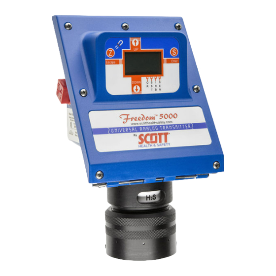
Page 15: Figure 1. Freedom 5000 With Integral Sensor
Freedom 5000 Universal Analog Toxic Gas Detector Instruction Manual Figure 1. Freedom 5000 with Integral Sensor 087-0020 REV E... -
Page 16: Overview Of Sensor Operation
Freedom 5000 Universal Analog Toxic Gas Detector Instruction Manual THE SCOTT SAFETY GAS SENSOR Overview of Sensor Operation Scott Safety manufactures two types of electrochemical gas sensors. These being the traditional GasPlus sensor and the Rock Solid GasPlus sensor. Both sensor types provide reliable gas detection but the Rock Solid... -
Page 17: Gas Specificity
Freedom 5000 Universal Analog Toxic Gas Detector Instruction Manual Gas Specificity Sensor battery failure Each gas sensor is engineered and designed to be gas specific; does not render the however, the very nature of electrochemical gas detection is such that... - Page 18 Freedom 5000 Universal Analog Toxic Gas Detector Instruction Manual Environmental Influences to the Scott Safety Sensor Although the Freedom™ 5000 transmitter is designed to operate at temperatures from -40° to 140°F (-40° to 60° C), the operating temperature is dictated by which gas sensor has been installed. The GasPlus Sensor Operating Parameters Addenda (see back of manual) show the operating temperature ranges for each sensor type.
- Page 19 Freedom 5000 Universal Analog Toxic Gas Detector Instruction Manual Sensor Oxygen Requirements Scott Safety “traditional” (not Rock Solid) gas sensors require a minimum of 5% oxygen for continuous operation under ambient conditions (except the Model 80 Oxygen sensor). Sensors operating in conditions of less than 5% oxygen will provide erroneous or unstable concentration data.
-
Page 20: Figure 3 Interface
Freedom 5000 Universal Analog Toxic Gas Detector Instruction Manual Series 5000 Transmitter General The General Purpose loop powered universal transmitter measures the sensor output current, conditions it, and converts it to a 4 – 20 mA current output. The Freedom™ 5000 requires a minimum of 3mA to operate and thus this is the lowest output the transmitter can output. - Page 21 Freedom 5000 Universal Analog Toxic Gas Detector Instruction Manual The non – intrusive set-up and calibration is achieved by 4 magnetically activated switches. Operation of these reed switches is performed by either touching (apply magnet to spot for ½ - 1 second) or touching and holding (for approximately 5 seconds) the particular spot/key.
-
Page 22: Figure 4 Inside View
Freedom 5000 Universal Analog Toxic Gas Detector Instruction Manual Power Supply & I/O PCB P/N 096-2499 CPU board is located behind power supply PCB P/N 096-2498 (SST) P/N 096-2498-1 (no SST option) See Figure 22 in rear of manual for sensor... -
Page 23: Figure 5 Dimensional Drawing (With Optional Wall Mount Bracket)
Freedom 5000 Universal Analog Toxic Gas Detector Instruction Manual Figure 5 Dimensional Drawing (with optional wall mount bracket) Freedom™ 5000 Installation Location Considerations Prior to installing the Series 5000 system, consideration should be given to the following items when choosing its location. -
Page 24: Typical Power Consumption
Freedom 5000 Universal Analog Toxic Gas Detector Instruction Manual 5. Vibration - Mount the transmitter and sensor in a manner that minimizes vibration. 6. Accessibility - When determining mounting location, consider future maintenance and calibration requirements. 7. Avoid water - Droplets adhering to the outer membrane of the sensor will reduce or negate sensor performance. -
Page 25: Figure 6 L Mounting Bracket
Freedom 5000 Universal Analog Toxic Gas Detector Instruction Manual Figure 6 L Mounting Bracket Installation is as follows: STEP 1 - Make all physical connections (i.e., conduits, pipes, enclosure, plastic spacer block, junction box, etc.) STEP 2 - Loosen transmitter screws and pull down front panel lid. -
Page 26: Figure 7 Wiring & Testing
Freedom 5000 Universal Analog Toxic Gas Detector Instruction Manual provide the force. This prevents the possibility of pulling the screw sockets out of the housing. STEP 5 – Install the sensor into the sensor housing. Make sure the elastomeric pad is between the sensor and the sensor housing concentric rings. -
Page 27: Figure 8 Installation Of E-Pad, Gasplus Sensor And Endcap
Freedom 5000 Universal Analog Toxic Gas Detector Instruction Manual 4-20ma Loop Connection Test Points TP1-Neg. TP2-Pos Start – Up Note If “F08” Sensor housing “O”-ring appears after power P/N 009-0039 has been applied, the sensor may not be making electrical contact with the transmitter. -
Page 28: Figure 9 E-Pad Separate & Installed In Endcap
Freedom 5000 Universal Analog Toxic Gas Detector Instruction Manual Alignment pin – fits into sensor hole Alignment Figure 9 E-Pad Separate & Installed in Endcap Note: The elastomeric pad can be installed with either side up/down 087-0020 REV E... -
Page 29: Figure 10 Remote Sensor And Flat Duct Mount
Freedom 5000 Universal Analog Toxic Gas Detector Instruction Manual Remote Sensor Mounting Many applications require that the sensor be mounted remote from the transmitter, e.g., duct mount application. In these applications, it is important that the sensor be separated from the transmitter no more than 50’. Scott Safety provides three different remote mount installations. -
Page 30: 1/4 Turn Twist And Lock Accessories
Freedom 5000 Universal Analog Toxic Gas Detector Instruction Manual 1/4 Turn Twist and Lock Accessories Designed for quick, easy installation and removal from your GasPlus sensor, Twist-and- Lock accessories connect directly to the standard end cap and help make your gas detection system easier to use. -
Page 31: Alarm And Loop - Power Inhibit
Freedom 5000 Universal Analog Toxic Gas Detector Instruction Manual Start – Up Front Panel Operations and Indications Initial System Start - Up Once all transmitters (sensor, rain shield, etc.) have been assembled and installation ™ has been completed, the DC supply to the Freedom 5000 Transmitter may be energized. -
Page 32: Figure 15 Setting Inhibit
Freedom 5000 Universal Analog Toxic Gas Detector Instruction Manual At this time the loop output automatically goes to 4 mA. 3. Hold the magnet over either the “Up” or “Down” magnetic switch and adjust to the desired level. 4. Hold the magnet momentarily over the “S”- Enter switch. - Page 33 Freedom 5000 Universal Analog Toxic Gas Detector Instruction Manual Remote Sensor Calibration ™ The Freedom 5000 is designed so the sensor may be removed from the transmitter and calibrated at a remote location. Fixed gas detection installations using this feature should utilize a documented calibration log (see “Calibration Frequency”) to determine...
-
Page 34: Figure 16 Zero Calibration
Freedom 5000 Universal Analog Toxic Gas Detector Instruction Manual Zero Calibration The transmitter’s zero is set by adjusting the loop output to 4 mA while the sensor is exposed to air which is free of the gas being detected (and any interferent gases which may be present). - Page 35 Freedom 5000 Universal Analog Toxic Gas Detector Instruction Manual Step 3 – If spanning the instrument, proceed to “Span Calibration STEP 2”. Observe the LCD indicates the “IHB” function is deactivated (the transmitter will automatically deactivate inhibit mode after 9 minutes).
- Page 36 Freedom 5000 Universal Analog Toxic Gas Detector Instruction Manual The transmitter should begin to respond to the calibration gas within 30 seconds. The indicated gas concentration should slowly level off to a value (usually close to that of the span gas concentration) and remain stable. Once this value has reached equilibrium it is time to span the transmitter/sensor.
- Page 37 Freedom 5000 Universal Analog Toxic Gas Detector Instruction Manual has to do with some internal makeup of the sensor, which can deteriorate over time. Although not normally expected, it is possible. It is mandatory that any HF or Rock Solid Acid Gas sensor calibrated with chlorine also be bumped tested with a acid gas.
- Page 38 Freedom 5000 Universal Analog Toxic Gas Detector Instruction Manual A Fail indication is usually a result of either a removed or poor sensor-to-housing electrical connection or sensor failure discovered by the self-diagnostic routine. The self- diagnostic routine interrogates transmitter and sensor memory transfer integrity and is continuously performed by the Series 5000 transmitter.
-
Page 39: Figure 17 With Sst Option
Freedom 5000 Universal Analog Toxic Gas Detector Instruction Manual oFF: Turns off SST function. This also clears the self test fault. On and or 01d: Immediately turns on the SST function and it will continue to activate every 24 hours from that point. -
Page 40: Figure 18 Sensor Self Test Generator
Freedom 5000 Universal Analog Toxic Gas Detector Instruction Manual b. The inhibit (Ihb) and Sensor Self Test (SST) indicator flags appear in the display. 3. After successfully measuring a concentration of 10%FS or more, the instrument turns off the gas generator and enters a recovery period while maintaining the inhibit state. -
Page 41: System Maintenance
Freedom 5000 Universal Analog Toxic Gas Detector Instruction Manual System Maintenance General For maximum safety, perform a sensor response test weekly; see “Making Operational Check Gases” in this section. The only other maintenance requirements are that the unit be zeroed and calibrated at regular intervals. - Page 42 Freedom 5000 Universal Analog Toxic Gas Detector Instruction Manual The following methods can be used during operational response checks of the transmitter: For GasPlus sensors detecting: Cl , ClO , Br Place a teaspoon of powdered calcium hypo chlorite in a small plastic bottle and cap tightly.
-
Page 43: Figure 20 096-2002
Freedom 5000 Universal Analog Toxic Gas Detector Instruction Manual Troubleshooting The elastomeric pad is often the source of problem transmitters and can be easily checked by substituting a new pad. General Should a problem in the operation of a Freedom™ 5000 occur, the first step is to isolate the problem to the component which has failed. - Page 44 Freedom 5000 Universal Analog Toxic Gas Detector Instruction Manual STEP 6 – Set the voltage calibrator to input 0.550 mV. Using the magnetic tip of the screwdriver, touch the magnet to the “S” span point on the transmitter body and hold it there. After four seconds the bar graph will disappear and the reading will begin to flash.
- Page 45 Freedom 5000 Universal Analog Toxic Gas Detector Instruction Manual Sensor Zero and Span Calibration Elastomeric Pad Bump Test Any Boards Zero and Span Calibration Any Filter Zero and Span Calibration Resetting Factory Default Calibration Values to Sensor “Z” “S” By applying a magnet simultaneously to the spots on the Freedom™...
- Page 46 Freedom 5000 Universal Analog Toxic Gas Detector Instruction Manual 8. Set-up and calibration must now be carried out to complete the board change. Power Supply – I/O Board Removal Follow steps 1 through 4 listed under the CPU board removal.
-
Page 47: Table 2. Conventional Sensors Part List (Not Rock-Solid)
Freedom 5000 Universal Analog Toxic Gas Detector Instruction Manual Table 2. Conventional Sensors Part List (Not Rock-Solid) Part Description Scott P/N P/N Suffix Ammonia (NH ) – Model 85 096-1965 -XXXX 50 ppm 096-1965 -0050 100 ppm 096-1965 -0100 250 ppm... - Page 48 Freedom 5000 Universal Analog Toxic Gas Detector Instruction Manual Table 2. Conventional Sensors Part List (Not Rock-Solid) Part Description Scott P/N P/N Suffix 50 ppm 096-1958 -0050 Hydrogen Cyanide (HCN) - Model 64 096-1952 -XXXX 25 ppm 096-1952 -0025 100 ppm...
- Page 49 Freedom 5000 Universal Analog Toxic Gas Detector Instruction Manual Table 2. Conventional Sensors Part List (Not Rock-Solid) Part Description Scott P/N P/N Suffix - Model 84 096-1964 -XXXX 10 ppm 096-1964 -0010 Ozone (O - Model 60 096-1948 -XXXX 1 ppm...
-
Page 50: Table 3. Rock Solid Sensor Part List
Freedom 5000 Universal Analog Toxic Gas Detector Instruction Manual Table 3. Rock Solid Sensor Part List Part Description Scott P/N P/N Suffix 10 ppm 096-2247 -0010 20 ppm 096-2247 -0020 Chlorine (Cl ) Hi Humidity - Model 24 096-2295 -XXXX... - Page 51 Freedom 5000 Universal Analog Toxic Gas Detector Instruction Manual Table 3. Rock Solid Sensor Part List Part Description Scott P/N P/N Suffix Hydrogen Fluoride (HF) Hi Humidity - Model 91 096-2331 -XXXX 5 ppm 096-2331 -0005 10 ppm 096-2331 -0010...
- Page 52 Freedom 5000 Universal Analog Toxic Gas Detector Instruction Manual Freedom™ 5000 Spare Parts Part Description Rainshield, End-Caps, Adaptors, Filters 1/4 Turn Calibration Adaptor 096-2101 1/4 Turn Rain Shield 074-0305 1/4 Turn Flowcell . 096-2669 NOTE 3 1/4 Turn Sensor End Cap . See...
- Page 53 Freedom 5000 Universal Analog Toxic Gas Detector Instruction Manual Spare Parts - continued Part Description Electronic Boards I/O and Power Supply Board 096-2499 CPU Board 096-2498-1 CPU Board with SST 096-2498 Display Board 096-2497 PCB Cable Assembly 096-2613 (Connects Display Board to Power Supply Board) Housing &...
- Page 54 Freedom 5000 Universal Analog Toxic Gas Detector Instruction Manual Freedom™ 5000 Model Configuration Model 50AA -BB - C - D - E - F AA: Type of Gas Select from the Master Gas List for gas and range. Ranges 01- No Sensor...
- Page 55 Freedom 5000 Universal Analog Toxic Gas Detector Instruction Manual Scott Safety Warranty eneral Policy Coverage ultimate The manufacturer warrants to the original purchaser and /or customer of the manufacturer’s products that if any part(s) thereof except for those listed below) prove(s) to be defective in material or workmanship within 18 months from the date of shipment or 12 months from the date of start-up, whichever comes first.
- Page 56 Freedom 5000 Universal Analog Toxic Gas Detector Instruction Manual Contacting Scott Safety Scott Safety 4320 Goldmine Rd Monroe, North Carolina 28110 USA Phone (800) 247-7257 • FAX (704) 291-8330 www.scottsafety.com Technical Specification Transmitter enclosure: NEMA-4X Noryl plastic with stainless steel screws & hinge 2ea ½”...
-
Page 57: Figure 21 Supply Voltage - Cd
Freedom 5000 Universal Analog Toxic Gas Detector Instruction Manual Note: On intrinsically safe loops, diode shunt barriers will add extra load to the loop. Current mirror barriers will not. Consult the barrier manufacturer for further information. Maximum Loop Load 1000 Supply Voltage - DC Figure 21 Supply Voltage –... - Page 58 Freedom 5000 Universal Analog Toxic Gas Detector Instruction Manual Intrinsic Safety The Freedom™ 5000 has been designed to be intrinsically when used with an approved safety barrier. Refer to Figure for “Generic Intrinsically Safe Barrier Wiring Diagram”. An intrinsically safe circuit is simply defined as: "an electrical circuit which does not contain, or store, enough energy to cause ignition of a given explosive atmosphere”.
- Page 59 Freedom 5000 Universal Analog Toxic Gas Detector Instruction Manual 087-0020 REV E...
-
Page 60: Figure 22 I. S. Barrier Wiring Diagram
Freedom 5000 Universal Analog Toxic Gas Detector Instruction Manual Figure 22 I. S. Barrier Wiring Diagram 087-0020 REV E... - Page 61 Freedom 5000 Universal Analog Toxic Gas Detector Instruction Manual 087-0020 REV E...
- Page 62 Monroe Corporate Center P.O. Box 569 Monroe, NC 28111 Teléfono: (800) 247-7257 Fax: (704) 291-8330 Sitio web: www.scottsafety.com 087-0020 REV E...
Need help?
Do you have a question about the FREEDOM 5000 and is the answer not in the manual?
Questions and answers