
Summary of Contents for Eminox CRT System
- Page 1 ® System Operation & Maintenance Manual E x h a u s t E n g i n e e r i n g E x c e l l e n c e LITM002...
-
Page 3: Table Of Contents
® System Operation & Maintenance Manual Contents Section Title Page Nos. Introduction 1. Technical Description & Identification of Parts 2. ® System Operation 3. Regular Maintenance Check 4. ® System Service Intervals Electronic Service Indicator ® 6. System Service Records Dismantling your CRT ® System 8. Re-assembling your CRT ® System ® 9. Servicing the CRT System Filter 10. Catalyst Maintenance 11. Summary of Warnings Glossary of Terms... -
Page 4: Introduction
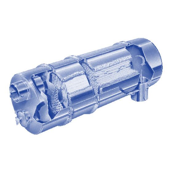
® System Operation & Maintenance Manual Wall-Flow Filter Module Highly Active Catalyst Module Inlet Module Outlet Port to facilitate Module smoke or back pressure testing Introduction Your CRT ® system is a Continuously Regenerating Trap using novel patented technology which largely eliminates harmful pollutants from your diesel engine exhaust, in addition to providing the normal functions of a silencer system such as noise reduction. Typical reductions for some of the major pollutants are: Particulate matter (PM) 75 to 95% Hydrocarbons (HC) 75 to 95% Carbon Monoxide (CO)75 to 95% Nitrogen Oxides (NOx) up to 10% Your CRT ®... -
Page 5: Technical Description & Identification Of Parts
Section 1 - Technical Description & Identification of Parts Your CRT ® system is made up of four major parts illustrated in the diagram below: 1. Inlet Module 2. Catalyst Module 3. Filter Module 4. Outlet Module 2. Catalyst 3. Filter 4. Outlet 1. Inlet Module Module Module Module Exhaust gas To Tailpipe from engine Service Port if fitted 2. Catalyst 3. Filter Module Module Plugged Cells (“Chequer board” structure ie: Alternate cells Open Cells are plugged) (“Honeycomb” structure) Both made Catalyst Filter from Ceramic Substrate Note: 1. In certain circumstances modules may be combined. 2. The Catalyst must always be positioned upstream of the Filter. -
Page 6: Crt ® System Operation
® System Operation & Maintenance Manual Section 2 - CRT ® System Operation ® System Operating Characteristics. ® The essential characteristic of the CRT system is to capture and oxidise the soot or particulate matter contained in diesel exhaust, commonly observed as smoke. The particulate matter is caught within the wall flow filter and then continuously oxidised, at typical exhaust gas temperatures, into harmless gas by the novel patented chemical technology. Under normal operating conditions, with a properly maintained engine under typical loading, the soot component of diesel exhaust is oxidised harmlessly leaving only ash, mainly the incombustible residue of burnt engine oil. This accumulates very gradually in the Filter and should be removed by regular servicing. - Page 7 >= 1.25 < 1.0 >= 1.0 < 0.8 >= 0.8 • Eminox approve the use of E4 and E6 oil. Eminox recommend the use of E6 rated engine oils ahead of E4, because of their potential to extend catalyst life and the advantages of extended filter service intervals. Which ever oil is used, it is important to ensure that it is a low ash engine oil with a sulphur content of less than 7,000 ppm. • Eminox recommend that oil consumption is monitored closely. It is important that oil consumption rates should not exceed engine manufacturer’s limits, typically less than 1 litre per 1,000km...
-
Page 8: Regular Maintenance Check
Record BP using: • an Electronic Service Indicator (ESI) if this is fitted, see Section 5 • Eminox hand held Digital Pressure Gauge (Part Number QM1466) connected by a tube to the BP tapping point fitted to your system. This could be to a Schrader valve output located within the engine bay or at some other easily accessible position, or ®... - Page 9 The BP Limit is the conservative figure that Eminox Ltd will provide for your engine configuration which can help to take account of these uncertainties. Best practice is to record BP readings under similar measurement conditions (see Section 2) at intervals of not more than 4 weeks.
-
Page 10: Electronic Service Indicator
ESI Warning System. The ESI warning system consists of 3 coloured lights. Limits are set within the micro-processor by Eminox Ltd for a particular engine configuration and duty cycle. The ESI triggers the appropriate light illumination when a preset BP has been exceeded: Green. System on, BP at acceptable levels Amber. BP above acceptable levels. Filter will require servicing shortly. -
Page 11: Crt ® System Service Records
This can be downloaded for analysis. Resetting the unit to carry out a max static rpm pressure reading does not erase this memory. ® Section 6 - CRT System Service Records. The following information should be recorded on your vehicle check sheet at each service: • Back Pressure before and after service (note that the engine must be warm at the time of measurement) • Vehicle mileage • Filter and Catalyst Serial Numbers • Filter cleaning, method and date Note: Eminox Ltd will require service records in order to investigate any warranty claim. Failure to provide service records will invalidate your warranty cover. A typical CRT ® system Service Record Sheet can be obtained from the Eminox Ltd website www.eminox.com... -
Page 12: Dismantling Your Crt ® System
Caution: Before dismantling your CRT system you should observe the requirements of your Health & Safety Risk Assessment. Note: Unless the Filter is already marked with the exhaust gas flow direction through the Filter, this should be marked on the outside of the casing before removal, unless it is to be returned to be reconditioned as an Eminox Ltd Service Exchange Filter. Your CRT ® system may be removed as a complete unit by slackening Inlet Module and Outlet Module pipe retaining Band Clamps and dismantling the supporting brackets as necessary. Some installations like twin systems may require that one... -
Page 13: Re-Assembling Your Crt ® System
V-Clamp Gasket Joint ring Section 8 - Re-assembling your CRT ® System Caution: Before re-assembling your CRT ® system you should observe the requirements of your Health & Safety Risk Assessment. Re-assemble your CRT ® system in the reverse sequence using new gaskets and, if needed, new V-clamps. The Catalyst Module may be re-assembled in either direction and must be fitted upstream of the Filter. The Filter should be replaced so as to maintain the marked previous exhaust gas flow direction. ® Note: It is recommended that the Filter Module is refitted with the CRT system Serial No and ID No easily visible to the Vehicle and Operations Services Agency (VOSA) for the purposes of their Reduced Pollution Certificate (RPC) inspections. Serial No. - Page 14 ® System Operation & Maintenance Manual The following torque settings should be applied. Note that it is essential not to over-tighten the clamps that provide the structural rigidity of the CRT ® system as this can lead to in service failure which could have serious results. • ® system Band Clamps (pipe work) 14 Nm • ® system V-Clamps 14 Nm • Hi-Torque Clamps (heat shields) 11 Nm • Service Port Plug (if fitted) 68 Nm • Allen Screws 20 Nm ® Following the replacement of the CRT system and all exhaust pipes: • Connect the garage exhaust extractor and start the engine. • Allow the engine to reach normal operating temperature. • Run at idle for five minutes, then gradually increase to full rpm. Then leave on tick over for 5 minutes before shutting off the engine. Remove the exhaust extractor unit and check the security of CRT ®...
-
Page 15: Servicing The Crt ® System Filter
A range of filter servicing packages are available, for details please visit www.eminox.com or contact us on +44(0)1427 810088 The environmental benefits of fitting an Eminox Systems are well established ® Systems significantly reduce exhaust emissions, including Carbon Monoxide, Hydrocarbons and Particulate Matter, FBC systems also reduce particulate matter, the SCRT ®... -
Page 16: Catalyst Maintenance
® System Operation & Maintenance Manual Section 10 - Catalyst Maintenance Caution: Before maintaining your Catalyst you should observe the requirements of your Health & Safety Risk Assessment. When operating under Normal Conditions the Catalyst should not become clogged by soot. However, during a Filter service it is advisable to check the condition of the Catalyst and to dislodge any accumulated soot by using a soft brush. Inspect those visible surfaces of the Catalyst that are accessible (not always possible on the upstream side) to ensure that there is no surface cracking or pitting and that the ceramic substrate is secure within the high grade stainless steel housing. Should any defect be found, replace the Catalyst Module. -
Page 17: Summary Of Warnings
Allow any insulation material to become dislodged. Always: • Service the filter when a Back Pressure limit is reached or when a BP graph indicates a rapid rise • Re-assemble a filter correctly with the marked or previous gas flow direction • Use fuel with a sulphur content less than 50 ppm, • Use fuels, fuel additives or alternative fuels which conform to EN590, or which are specifically approved by Eminox Ltd • Use E4 or E6 oil. Eminox recommend the use of E6 rated engine oils ahead of E4, because of their potential to extend catalyst life and the advantages of extended filter service intervals. Which ever oil is used, it is important to ensure that it is a low ash engine oil with a sulphur content of less than 7,000 ppm. -
Page 18: Glossary Of Terms
® System Operation & Maintenance Manual Glossary of Terms Term Meaning Ash The incombustible particulate matter in the exhaust gas, mainly residues of components of the lubricating oil. Back Pressure The pressure above atmospheric within an exhaust system caused by flow resistance. Band Clamps Flat metal clamps which are used to connect your CRT ® System to the exhaust pipes. Catalyst A ceramic substrate coated with precious metals to oxidise pollutants in the exhaust gas. - Page 19 Website www.eminox.com Email enquiry@eminox.com Telephone +44 (0) 1427 810088...
- Page 20 Eminox Ltd North Warren Road, Gainsborough, Lincolnshire, DN21 2TU. Tel: +44 (0) 1427 810088 Fax: +44 (0) 1427 810061 www.eminox.com...
Need help?
Do you have a question about the CRT System and is the answer not in the manual?
Questions and answers