Table of Contents
Advertisement
Quick Links
PILOT´S OPERATING
HANDBOOK
Document Number: AS-POH-10-487
Date of Issue: 07. 05. 2019
Aircraft Model: WT9 Dynamic LSA / Club
Aircraft Serial Number: DY-487/2013 LSA
Aircraft Registration Number: F-HVXC
THIS HANDBOOK INCLUDES THE INFORMATION REQUIRED TO BE FURNISHED TO THE PILOT
BY REGULATIONS AND ADDITIONAL INFORMATION PROVIDED BY THE AIRCRAFT
MANUFACTURER – AEROSPOOL, SPOL. S R. O.
PAGES MARKED AS "EASA APPROVED" ARE APPROVED BY EUROPEAN AVIATION SAFETY
AGENCY.
THIS AIRCRAFT MUST BE OPERATED IN COMPLIANCE WITH THE INFORMATION AND
LIMITATIONS STATED IN THIS MANUAL.
Advertisement
Chapters
Table of Contents

Related Manuals for Aerospool WT9 Dynamic LSA / Club

Summary of Contents for Aerospool WT9 Dynamic LSA / Club
- Page 1 PILOT´S OPERATING HANDBOOK Document Number: AS-POH-10-487 Date of Issue: 07. 05. 2019 Aircraft Model: WT9 Dynamic LSA / Club Aircraft Serial Number: DY-487/2013 LSA Aircraft Registration Number: F-HVXC THIS HANDBOOK INCLUDES THE INFORMATION REQUIRED TO BE FURNISHED TO THE PILOT BY REGULATIONS AND ADDITIONAL INFORMATION PROVIDED BY THE AIRCRAFT MANUFACTURER –...
- Page 2 This page is left blank intentionally...
- Page 3 RECORD OF REVISIONS Any revision of the present manual, except actual weight data, must be recorded in the following table, and in the case of approved chapters, endorsed by the responsible airworthiness authority. The new or amended text in the revised pages will be indicated by a black vertical line in the page margin, and the revision will be shown on the bottom side of the page.
- Page 4 This page is left blank intentionally Page B Initial issue...
- Page 5 LIST OF EFFECTIVE PAGES Chapter Page Status Chapter Page Status Title page Initial issue Initial issue Page Initial issue EASA Approved Initial issue Page A Initial issue EASA Approved Initial issue Page B Initial issue EASA Approved Initial issue Page C Initial issue EASA Approved Initial issue...
- Page 6 Chapter Page Status Chapter Page Status 4-18 Initial issue EASA Approved 6-17 Initial issue 4-19 Initial issue EASA Approved 6-18 Initial issue 4-20 Initial issue EASA Approved 6-19 Initial issue 4-21 Initial issue EASA Approved 6-20 Initial issue 4-22 Initial issue EASA Approved 6-21 Initial issue...
- Page 7 Chapter Page Status Chapter Page Status 7-37 Initial issue 7-38 Initial issue 7-39 Initial issue 7-40 Initial issue 7-41 Initial issue 7-42 Initial issue 7-43 Initial issue 7-44 Initial issue Initial issue Initial issue Initial issue Initial issue Initial issue Initial issue Initial issue Initial issue...
- Page 8 Chapter Page Date Chapter Page Date Page F Initial issue...
-
Page 9: Table Of Contents
TABLE OF CONTENTS Chapter Chapter Name INTRODUCTION ........................GENERAL INFORMATION ..................... LIMITATIONS ......................... EMERGENCY PROCEDURES ..................NORMAL PROCEDURES ....................PERFORMANCE ........................WEIGHT AND BALANCE, AND EQUIPMENT LIST ......... DESCRIPTION OF AIRCRAFT AND SYSTEMS ............ HANDLING AND SERVICING ..................SUPPLEMENTS ........................Initial issue Page G... - Page 10 This page is left blank intentionally Page H Initial issue...
- Page 11 0 INTRODUCTION TABLE OF CONTENTS GENERAL ....................... 0-2 LIST OF STANDARDS....................0-2 CONTINUED AIRWORTHINESS ................0-2 AIRCRAFT MANUFACTURER CONTACT INFORMATION ..........0-2 DATA LOCATION AND CONTACT INFORMATION FOR RECOVERY OF APPROVAL DOCUMENTATION ....................0-2 SYMBOLS, ABBREVIATIONS AND TERMINOLOGY ............ 0-3 Speed ..........................
-
Page 12: General
The noise requirements are shown according to Certification Specifications and Acceptable Means of Compliance for Aircraft Noise CS-36, Amendment 3 dated 20 January 2013. Continued Airworthiness Technical publications for continued airworthiness are released on the Aerospool website www.aerospool.sk and they may be downloaded free of charge. -
Page 13: Symbols, Abbreviations And Terminology
Symbols, Abbreviations and Terminology Speed Calibrated airspeed; Indicated speed in kilometers per hour corrected for installation and instrument errors. CAS is equal to TAS in standard atmospheric conditions at MSL. KCAS CAS indicated in knots. Indicated airspeed in kilometers per hour as shown on the airspeed indicator. KIAS IAS indicated in knots. -
Page 14: Power Plant
Power Plant Horsepower Kilowatt Takeoff Power Maximum engine power for takeoff. Maximum Continuous Power Maximum permissible continuous engine output power during flight. Flight Performance and Flight Planning Demonstrated Crosswind Component The maximum speed of the crosswind component at which the maneuverability of the aircraft during takeoff and landing has been demonstrated during type certification test flights. -
Page 15: Equipment
Equipment Altitude or Altimeter Airspeed Indicator Course Deviation Indicator COMM Communication Transceiver Course EFIS Electronic Flight Information System Emergency Locator Transmitter Engine Monitoring System Emergency Parachute System Global Positioning System Heading Multi-function Display Original Equipment Manufacturer, company that controls the engineering and design rights for the LSA or an assembly, subassembly, accessory, or part installed in the aircraft, the consumable material, tools, fixtures, and test equipment used to service or maintain the aircraft. -
Page 16: Conversion Factors
Conversion Factors Length or Altitude 1 [m] = 3.281 [ft] 1 [ft] = 0.305 [m] 1 [m] = 39.37 [in] 1 [in] = 0.0254 [m] 1 [km] = 0.5399 [nm] 1 [nm] = 1.852 [km] Speed 1 [km/h] = 0.54 [knots] 1 [knots] = 1.852 [km/h] 1 [m/s] = 1.9425 [knots] 1 [knots] = 0.5148 [m/s]... - Page 17 1 GENERAL INFORMATION TABLE OF CONTENTS GENERAL ....................... 1-2 INTRODUCTION TO THE POH .................. 1-2 Warnings, Cautions and Notes ..................1-2 Procedures ........................1-2 INTRODUCTION TO THE AIRCRAFT ................. 1-3 Dimensions ........................1-3 Engine ..........................1-3 Propeller ......................... 1-3 Three View Drawing ....................... 1-4 Ground Turning Clearance .....................
-
Page 18: General
General This chapter contains information of general interest to pilots and owners. You will find useful information to familiarize yourself with the aircraft, such as dimensions, ground turning clearance, loading, fuelling and summary of performance. Introduction to the POH Warnings, Cautions and Notes The following highlighting styles are used in this handbook to focus attention on particular information that is important. -
Page 19: Introduction To The Aircraft
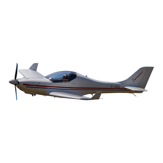
Introduction to the Aircraft Dimensions Wing area 10.500 m 112.98 ft Wing span 8.926 m 29.28 ft Overall length 6.460 m 21.19 ft Maximum height 1.850 m 6.07 ft Wheel base 1.400 m 4.59 ft Main landing gear track 2.240 m 7.35 ft Maximum propeller diameter 1.750 m... -
Page 20: Three View Drawing
Three View Drawing Fig. 1-1 Three view drawing Page 1-4 Initial issue... -
Page 21: Ground Turning Clearance
Ground Turning Clearance Fig. 1-2 Ground turning clearance Wing tip radius 9.850 m 32.32 ft Outside main gear radius 6.500 m 21.32 ft Nose gear radius 5.380 m 17.65 ft Inside main gear radius 4.260 m 13.98 ft CAUTION The data are valid for dry paved surface, fully turned nose gear and minimum taxi speed! Expect greater turning radius on unpaved, wet and/or slippery surfaces! Initial issue... -
Page 22: Summary Of Performance
Summary of Performance NOTE All airspeeds shown in the POH are IAS / KIAS, unless not stated otherwise. Weights Maximum takeoff weight 600.0 kg 1323 lb Maximum landing weight 600.0 kg 1323 lb Empty weight Max. 410.8 kg Max. 906 lb Maximum load per seat 120.0 kg 265 lb... -
Page 23: Fuel Operating Ranges
Fuel Operating Ranges Endurances and ranges at altitude 2000 ft ISA Engine speed 4 300 4 500 4 800 5 000 5 500 Fuel consumption 14.5 15.5 17.2 18.5 21.3 km/h KIAS knots km/h KCAS knots km/h KTAS knots hh:mm 8:12 7:40 6:55... -
Page 24: Approved Fuel Types And Fuel Capacity
Approved Fuel Types and Fuel Capacity EN 228 Super Approved types of fuel (Min. RON 95) EN 228 Super Plus AVGAS 100 LL 126.0 l 33.29 U. S. gal Total capacity of fuel tanks 90.7 kg 200 lb 119.0 l 31.44 U. -
Page 25: Limitations
2 LIMITATIONS TABLE OF CONTENTS GENERAL ....................... 2-3 AIRSPEED LIMITATIONS ..................2-3 Airspeed Indicator Marking.................... 2-3 Stalling Speeds at Maximum Takeoff Weight (V and V ) ..........2-3 Flap Extended Speed Range (V – V ) ................2-3 Operating Maneuvering Speed (V ) ................ - Page 26 2.14 OTHER LIMITATIONS .................... 2-13 Smoking ........................2-13 Dynon SkyView System Limitations ................2-13 External Power Source and Battery ................2-13 2.15 PLACARDS ......................2-14 Interior Placards ......................2-14 Exterior Placards ......................2-15 Page 2-2 EASA Approved Initial issue...
-
Page 27: General
General The limitations included in this section are approved by the European Aviation Safety Agency. Chapter 2 includes operating limitations, instrument markings, and basic placards necessary for safe operation of the aircraft, its standard systems and equipment. WARNING Aircraft must be operated within the limitations stated in this chapter! Airspeed Limitations Airspeed Indicator Marking... -
Page 28: Operating Maneuvering Speed (V )
Operating Maneuvering Speed (V at maximum takeoff Do not make full or abrupt control 180 IAS 97 KIAS weight movements above this airspeed, because under certain conditions the aircraft may at minimum flying be overstressed by full control deflections. 140 IAS 76 KIAS weight Never Exceed Speed (V... -
Page 29: Power Plant Limitations
Power Plant Limitations Engine Limitations Engine manufacturer BRP-Powertrain GmbH&Co.KG Engine model number Rotax 912 ULS2 73.5 kW / 100.0 hp at 5800 rpm Max. takeoff (max. 5 min.) Engine power Max. continuous 69.0 kW / 92.5 hp at 5500 rpm Takeoff 5800 rpm (max. -
Page 30: Power Plant Instrument Markings
Power Plant Instrument Markings Digital power plant instrument SkyView SV D1000 for monitoring of engine parameters complemented with analogue engine speed indicator and fuel pressure indicator are marked with following color code significance: Dynon SkyView Red Line Green Arc Yellow Arc Red Line Unit Minimum Limit... -
Page 31: Weight Limits
Weight Limits Maximum takeoff weight 600.0 kg 1323 lb Maximum landing weight 600.0 kg 1323 lb Minimum flying weight 405.0 kg 893 lb Maximum load per seat 120.0 kg 265 lb Maximum total baggage weight 2x 20.0 kg 2x 44 lb WARNING Do not exceed maximum takeoff weight 600.0 kg! WARNING... -
Page 32: Approved Maneuvers
Approved Maneuvers Aerobatic maneuvers, including spins are prohibited. The aircraft is not approved for pitch attitudes greater than 30°. The aircraft is not designed for aerobatic operations. Only those operations incidental to normal flight are approved. These operations include normal stalls (except whip stalls), chandelles, lazy eights and turns in which the bank angle does not exceeding 60°. -
Page 33: Fluids
Fluids Fuel The electric fuel pump must be ON for takeoff and landing. The electric fuel pump is connected to LH fuel tank only. EN 228 Super Approved types of fuel (min. RON 95) EN 228 Super Plus AVGAS 100 LL 126.0 l 33.29 U. -
Page 34: Oil
Oil capacity is 3.0 – 3.5 l (oil system + oil tank). CAUTION Use only suitable oil according to the specification stated at placard in the engine compartment! CAUTION Never use AVGAS, LB 95 with fully synthetic engine oils! NOTE For complete oil specifications see OPERATORS MANUAL FOR ROTAX ENGINE TYPE 912 SERIES, Doc. -
Page 35: Environmental Limitations
2.10 Environmental Limitations Before starting preheat the engine and oil if outside temperature falls below +5 °C. Do not operate the aircraft below outside temperature -25 °C and above +50 °C. Flights in icing conditions are not allowed. WARNING Flights in icing conditions are prohibited! NOTE Cabin heating may be insufficient, when the outside temperature is below zero and the engine loading is low. -
Page 36: Systems And Equipment Limitations
2.13 Systems and Equipment Limitations Flap Limitations Normal takeoff FLAPS 1 Normal landing FLAPS 2 Emergency landing FLAPS 3 Emergency Parachute System The emergency parachute system must be operative. 290 CAS 157 KCAS Maximum airspeed 303 IAS 164 KIAS Minimum height above terrain 660 ft (200 m) WARNING The emergency parachute system must be operative, otherwise... -
Page 37: Minimum Equipment For Flight Operation
Minimum Equipment for Flight Operation Flight indications: Airspeed Altitude Magnetic compass Engine indications: Engine RPM Fuel pressure Manifold pressure Oil pressure Oil temperature Coolant temperature Exhaust gas temperature Airbox temperature Fuel quantity ATC equipment (radio, XPDR) Stall Warning System (buzzer, warning light) Safety harness for each occupied seat. - Page 38 2.15 Placards NOTE If any placard is found missing or unreadable it should be replaced. List of all placards is given in the Aircraft Maintenance Manual AS-AMM-10-000, Chapter 11. Interior Placards Placards on the left part of instrument panel. b. Placards on the left side of cabin. Placards on the / RH side of the baggage compartment bulkhead.
- Page 39 d. Placards on the / R side in the baggage compartment on the flap’s torsion tube cover. Exterior Placards Placards on the wing center section, wing flaps. b. Placards near fuel tank caps LH / RH. Placard on the upper engine cowling near door for oil level check. d.
- Page 40 h. Placards near drain valves on the wing bottom part. Placards are located on the both sides of fuselage under the windows in baggage compartment. Placard is located on the emergency parachute system cover. Page 2-16 EASA Approved Initial issue...
- Page 41 3 EMERGENCY PROCEDURES TABLE OF CONTENTS GENERAL ....................... 3-3 AIRSPEED FOR EMERGENCY PROCEDURES .............. 3-3 EMERGENCY ENGINE SHUTDOWN ON GROUND ............. 3-3 ENGINE FAILURE ....................3-4 Engine Failure on Takeoff Roll ..................3-4 Engine Failure on Takeoff up to Height 500 ft (150 m) AGL .......... 3-4 Engine Failure in Flight ....................
- Page 42 Overvoltage ........................3-17 Elevator Trim System Failure ..................3-17 Brake Failure during Taxi ....................3-17 Loss of Primary Instruments ..................3-18 3.10 INADVERTENT ICING ENCOUNTER ................ 3-20 3.11 LOSS OF FLIGHT CONTROLS .................. 3-21 Aileron Control Failure ....................3-21 Elevator Control Failure ....................3-21 Rudder Control Failure ....................
-
Page 43: Emergency Procedures
General While this chapter covers most emergencies and critical situations that could occur in the WT9 Dynamic LSA, it is not a substitute for a thorough knowledge of the aircraft and aviation techniques. Proper study of this chapter while on the ground will help you prepare for critical situations. -
Page 44: Engine Failure
Engine Failure Engine Failure on Takeoff Roll If the engine failure occurs during the takeoff roll, abort the takeoff and stop the aircraft. THROTTLE IDLE Brake As required FUEL PUMP IGNITION OFF both circuits Starter key MASTER SWITCH Fuel selector All switches Brake PARK... -
Page 45: Engine Failure In Flight
Engine Failure in Flight If the engine failure occurs during flight, pitch the nose down to establish the best glide speed. Select a suitable landing area and try to identify the cause of engine failure and correct it. If altitude or terrain does not permit a safe landing, activation of the EPS may be required (see Chapter 3.13.4). -
Page 46: Air Start
Air Start Airspeed 120 – 130 IAS / 65 – 70 KIAS Altitude Check Field selection Select according to available altitude AVIONICS External lights All OFF CHOKE THROTTLE Slightly OPEN (1 turn of throttle control) MASTER SWITCH Fuel selector Fullest tank FUEL PUMP ON (only if LH tank is selected) IGNITION... -
Page 47: Smoke And Fire
Smoke and Fire Engine fire is indicated by the red ENGINE FIRE warning light coming on. Engine Fire on Ground Brake FUEL PUMP Fuel selector THROTTLE IGNITION OFF both circuits after the engine has stopped Starter key MASTER SWITCH Safety harness Release Canopy Open (if stuck, break glass with best available means) -
Page 48: Engine Fire In Flight
Engine Fire in Flight FUEL PUMP Check OFF Fuel selector THROTTLE CABIN CLOSE HEATING/VENTILATION Windows CLOSE (if smoke is in the cabin OPEN) IGNITION OFF both circuits after the fuel has been consumed Fire Try to extinguish with a sideslip Smooth air –... -
Page 49: Cabin Fire On Takeoff And In Flight
Cabin Fire on Takeoff and in Flight Opening of cabin heating and venting may feed the fire. It may be necessary to ventilate the cabin to avoid of crew incapacitation from smoke inhalation. MASTER SWITCH CABIN HEATING / CLOSE to not feed the fire VENTILATION Fire source Locate... -
Page 50: Landing Emergencies
Landing Emergencies Precautionary Landing with Engine Power In the event of a major failure, disorientation, shortage of fuel, dangerous deterioration of meteorological conditions (visibility, thunderstorm) or the pilot experiencing nausea which could lead to incapacitation, a precautionary landing should be conducted. Landing area Select, determine wind direction Radio... -
Page 51: Landing With Flat Tire
Landing with Flat Tire If a flat tire occurs during takeoff and you cannot abort, land as soon as conditions permit. 3.8.2.1 Main Wheel Tire Safety harness Fasten Wing flaps FLAPS 3, extend gradually, check locked Airspeed 110 – 115 IAS / 59 – 62 KIAS THROTTLE As required Touch-down... -
Page 52: Emergency Landing Without Engine Power
Emergency Landing without Engine Power After establishing a glide or landing speed, perform as many of the checklist items as time permits. Airspeed 120 – 130 IAS / 65 – 70 KIAS Select a suitable landing area, if possible against the wind, and with no obstacles Emergency landing area on the final approach Radio... -
Page 53: Ditching
Ditching After establishing a descent, perform as many of the checklist items as time permits. RESCUE SYSTEM ACTIVATE according to Chapter 3.13.4 actuator Emergency call Transmit MAYDAY (121.5 MHz) giving position and intentions Transponder Set 7700 ELT REMOTE CONTROL ACTIVATE Aircraft Exit immediately Life vests and rafts... -
Page 54: System Emergencies
System Emergencies Low Oil Pressure Low oil pressure is indicated by the red OIL PRESS warning light coming on. Oil temperature Check If oil temperature is rising: THROTTLE Reduce power to minimum required for flight Landing Perform a precautionary landing in accordance with 3.8.1 If oil temperature is normal: Oil temperature Monitor... -
Page 55: Low Fuel Pressure
Low Fuel Pressure Fuel selector Fullest tank FUEL PUMP ON (only if LH tank is selected) If fuel pressure is decreasing: Landing Perform a precautionary landing in accordance with 3.8.1 If fuel pressure is normal: Fuel pressure Monitor Landing Perform at nearest airfield CAUTION Be prepared for engine failure and emergency landing without engine power according to Chapter 3.8.3! -
Page 56: Alternator Failure
Alternator Failure Loss of alternator output is detected through a zero or minus values reading on the ammeter and warning lamp CHARGE coming on. Electrical power malfunctions are accompanied by an excessive rate of charge or a discharge rate indicated by ammeter. THROTTLE Increase above 3000 rpm External lights... -
Page 57: Overvoltage
Overvoltage If the trouble was caused by a momentary overvoltage condition (16.5 V and up), the following procedure should return the voltmeter to a normal reading. THROTTLE Reduce power to minimum for flight AVIONICS External lights FUEL PUMP MASTER SWITCH OFF - ON If the overvoltage condition (16.5 V and up) is noted: All unnecessary... -
Page 58: Loss Of Primary Instruments
Loss of Primary Instruments The primary flight instruments are analogue airspeed indicator, altimeter and magnetic compass. The primary engine instrument is RH Dynon SkyView SV-D1000. If a failure of primary source of flight or engine information occurs, perform the following procedure: Loss of primary flight information (analogue instruments): LH D1000 or RH D1000 Use for flight information... - Page 59 Both RH and LH D1000 Frozen Screen or Black Out: Check pressed in – if open, reset (close) circuit breaker; if circuit breaker opens RH D1000 circuit breaker again, do not reset again Check pressed in – if open, reset (close) circuit breaker; if circuit breaker opens LH D1000 circuit breaker again, do not reset again RH D1000...
-
Page 60: Inadvertent Icing Encounter
3.10 Inadvertent Icing Encounter CARBUR. PREHEATING OPEN (pull to open) Leave - turn back or change altitude to obtain an outside air temperature that is Icing area less conducive to icing CABIN HEATING OPEN (pull to open) Increase engine speed to minimize ice build-up on the propeller blades; THROTTLE if excessive vibration is noted, immediately reduce engine speed to idle, and then rapidly apply full throttle... -
Page 61: Loss Of Flight Controls
3.11 Loss of Flight Controls Aileron Control Failure Rudder control As required THROTTLE As required, carefully CAUTION Avoid steep turns – more than 15° of bank! Elevator Control Failure THROTTLE As required, carefully TRIM As required If you cannot control the aircraft in the longitudinal direction by means of PITCH trim: Carefully use for attitude change (use incremental positions of flaps if required Wing flaps by holding the flaps lever in desired position) -
Page 62: Spins
3.12 Spins Inadvertent spin The WT9 Dynamic LSA is not approved for spins. Although the stall warning system makes accidental entry into a spin extremely unlikely, it is possible. The best means for preventing an inadvertent stall and spin entry is good airmanship, monitoring of the airspeed and avoiding abrupt maneuvers at low speed and altitude. -
Page 63: Other Emergencies
3.13 Other Emergencies Vibrations The power plant can be the source of the vibrations. Engine speed Reduce to minimize the vibrations Proceed to the nearest airport or select a suitable precautionary landing field Landing in accordance with 3.8.1 CAUTION Be prepared for engine failure and emergency landing without engine power according to Chapter 3.8.3! Fuel Selector Failure Due to fuel selector failure, it may be impossible to switch to the desired tank or shut off the fuel supply. -
Page 64: After Lift Off Or During Climbing
3.13.3.2 After Lift Off or during Climbing Takeoff Abort (if sufficient RWY is remaining), otherwise continue Climb Climb to safety altitude Keep straight level flight without sideslip and carry out procedure according Flight to Chapter 3.13.3.3 3.13.3.3 During Level Flight Sliding windows OPEN Airspeed... -
Page 65: Emergency Parachute System Activation
Emergency Parachute System Activation The aircraft is equipped with Emergency Parachute System. (EPS) should be activated in the event of a life-threatening emergency where EPS deployment is safer than continued flight and landing. Occupants must be in the emergency landing body braced position before touchdown. After touchdown, maintain the emergency landing body position until the aircraft is completely stopped. - Page 66 WARNING The extreme emergency in which the EPS must be activated requires that it be activated in a timely manner. Do not wait until the aircraft has exceeded the airspeed and load factor operating envelope, is at an altitude which does not allow the parachute to fully deploy prior to ground impact, or is in an extreme attitude! WARNING If the aircraft is controllable and structurally capable of flying...
- Page 67 4 NORMAL PROCEDURES TABLE OF CONTENTS GENERAL ....................... 4-3 AIRSPEEDS FOR NORMAL OPERATION ..............4-3 PRE-FLIGHT INSPECTION ..................4-4 BEFORE ENGINE STARTING................... 4-10 USE OF EXTERNAL POWER ................... 4-10 ENGINE STARTING ....................4-11 BEFORE TAXIING ....................4-13 TAXIING ....................... 4-13 BEFORE TAKEOFF ....................
- Page 68 4.18 ENVIRONMENTAL CONSIDERATION ..............4-23 Cold Weather Operation ....................4-23 Hot Weather Operation ....................4-23 4.19 OTHER NORMAL PROCEDURES ................4-24 Stall ..........................4-24 Sideslip ......................... 4-25 Crosswind Takeoff ......................4-26 Crosswind Landing ....................... 4-26 Page 4-2 Initial issue...
-
Page 69: General
General This chapter provides checklists and recommended procedures for normal operation of the aircraft. Normal procedures associated with equipment can be found in the Chapter 9. The control surfaces do not return to neutral or trimmed position automatically when the control is released. CAUTION The ailerons do not return to neutral automatically when the roll control is released! -
Page 70: Pre-Flight Inspection
Pre-Flight Inspection It is most important to perform a pre-flight inspection carefully to prevent possible troubles. The pre-flight inspection is essential for flight safety. Pre-flight inspection procedure is shown on Fig. 4-1. Review your flight plan and calculate the weight and balance before each flight. WARNING If any problems are found they must be rectified before flying! WARNING... - Page 71 CABIN Aircraft documents Check, on board Baggage Restrained Flight controls Freedom and proper direction of movement IGNITION OFF both circuits MASTER SWITCH THROTTLE Freedom of movement, set IDLE CARBUR. PREHEATING Freedom of movement, set CLOSED CABIN VENTILATION Freedom of movement CABIN HEATING Freedom of movement Fuel selector...
- Page 72 LEFT FUSELAGE Left wing walk Condition Surface Condition XPDR antenna Condition, attachment EMPENNAGE VOR antenna Condition, attachment Horizontal and vertical Condition stabilizers Elevator Condition, freedom of movement, without excessive play Rudder Condition, without excessive play Elevator / rudder Secured attachment Elevator / rudder sealing All in place, condition, attachment tapes...
- Page 73 RIGHT WING LEADING EDGE Surface Condition Pitot probe Remove cover, condition, check for blockage Leading edge and stall Condition, attachment, cleanness strips Fuel tank cap Condition, check quantity of fuel by means of dipstick and secure Inspection hole cover Installed Tie-down ropes Remove Fuel drains (2 underside)
- Page 74 WARNING Never crank the propeller by hand with IGNITION ON! Before cranking the propeller, ensure that nobody is in the cockpit! WARNING Do not replenish the coolant if the engine is hot. Always let the engine cool down to ambient temperature! CAUTION The propeller must be grabbed by the blade surface every time! NOSE LANDING GEAR...
- Page 75 LEFT WING TIP Winglet Condition NAV/ACL lights Condition, attachment LEFT WING TRAILING EDGE Condition, remove control locks if installed, freedom of movement, without Aileron excessive play Aileron attachment Secured Aileron sealing tapes All in place, condition, attachment Wing flap Condition, without excessive play Wing flap attachment Secured Initial issue...
-
Page 76: Before Engine Starting
Before Engine Starting Ground equipment Removed Pre-flight inspection Performed Co-pilot (passenger) Briefed Weight and balance Verified within limits for takeoff and landing RESCUE SYSTEM Remove lock (see Chapter 7.22, Fig. 7-33) actuator Safety harness Adjust and lock, not twisted Wing flaps FLAPS 0 Brake NOTE... -
Page 77: Engine Starting
Engine Starting Fuel selector LEFT (if the fuel tank volume is 45+, see Chapter 7.16) CHOKE - cold engine OPEN (pull to open) - warm engine CLOSE (push to close) THROTTLE IDLE - cold engine - warm engine Slightly open (1 turn of throttle controller) MASTER SWITCH ON, wait until Flight Display and MFD start up Instruments... - Page 78 CAUTION Do not actuate starter key as long as the engine is running. Wait until the engine is completely stopped! CAUTION After engine starting, if the oil pressure does not reach the minimum pressure 2.00 bar within 10 seconds, shut down the engine and investigate the cause! The loss of lubrication can cause severe engine damage! CAUTION...
-
Page 79: Before Taxiing
Before Taxiing Before taxiing, start the warming up period at 2000 rpm for approx. 2 minutes and continue at 2500 rpm. Duration depends on ambient temperature. Monitor temperatures and pressures. Carburetor preheating may be opened to shorten the warming up period. Warm up the engine until the oil temperature reaches 50 °C according to following procedure: CARBUR. -
Page 80: Before Takeoff
Before Takeoff Before takeoff the engine should be properly warmed. The engine oil temperature must reach min. 50 °C. Then the ignition and engine ground tests may be performed as follows: Ignition and Engine Ground Tests CARBUR. PREHEATING Check CLOSED Brake Ignition and engine ground tests: THROTTLE... -
Page 81: Before Line Up
CAUTION After an engine full-power ground test, allow a short cooling run to prevent vapor formation in the cylinder head! CAUTION When performing the engine full-power ground test on grassy or slick surface, the aircraft may move despite MAX brake being used! Before Line Up RESCUE SYSTEM... -
Page 82: Takeoff
4.10 Takeoff The engine should be properly warmed up before takeoff (oil temperature min. 50 °C). For takeoff over a gravel surface, apply the throttle slowly and the gravel will be blown behind the propeller rather than pulled into it. WARNING Takeoff is prohibited if: •... -
Page 83: Soft Field Takeoff
Soft Field Takeoff For takeoffs from a soft or rough field, it is recommended to lift the aircraft off the ground as soon as practical. The aircraft should be leveled after liftoff immediately to accelerate. Brake Release THROTTLE Smoothly MAX Engine parameters Check Control stick... -
Page 84: Climb
4.11 Climb Climb is performed with flaps retracted and maximum continuous power. For maximum rate of climb establish the best rate of climb. If an obstacle clearance is required using a steep climb angle, establish the best angle of climb speed. -
Page 85: Descent
4.13 Descent It is not advisable to reduce the engine power to idle when descending from a very high altitude. In such case the engine may become under-cooled and a loss of power may occur. It is recommended to descend at increased rpm (approximately 3000 rpm) and check the engine parameters are within permitted limits. -
Page 86: Landing
4.15 Landing WARNING Do not extend the flaps at speed above V WARNING When setting the flaps position FLAPS 1, FLAPS 2 always ensure that the flap lever is properly locked! If not locked properly, the flaps may retract inadvertently, which will cause the aircraft to pitch the nose up and lose of airspeed quickly! CAUTION Extending the flaps significantly increase the nose-heavy attitude! -
Page 87: Short Field Landing
Short Field Landing Landing approach is conducted at a small glide slope angle due to the long distance of the float before touchdown. Wing flaps FLAPS 2, extend gradually, check locked Airspeed 110 – 115 IAS / 59 – 62 KIAS TRIM As required THROTTLE... -
Page 88: Balked Landing
Balked Landing THROTTLE Smoothly MAX Wing flaps FLAPS 1 slowly, check locked Airspeed 122-127 IAS / 66-69 KIAS (see Chapter 5.5) FLAPS 0 slowly at safety altitude Wing flaps (not below 165 ft (50 m) AGL and 130 IAS / 70 KIAS) TRIM As required NOTE... -
Page 89: Shutdown
4.17 Shutdown Brake PARK THROTTLE IDLE Radio Transponder AVIONICS OFF the first circuit, after 2-3 s IGNITION OFF the second circuit Starter key MASTER SWITCH NAV/ACL lights RESCUE SYSTEM Install lock (see Chapter 7.22, Fig. 7-33) actuator CAUTION Do not park the aircraft in direct sunlight with the canopy left open (see Chapter 8.2.2)! NOTE Canopy cover prevents the effects of the sun. -
Page 90: Other Normal Procedures
4.19 Other Normal Procedures Stall The stall speeds are presented in the Chapter 5. When the airspeed is slowly reduced, an imminent stall is noticed by vibrations felt in the seat. To prevent an inadvertent stall, the aircraft is equipped with two independent stall warning systems. First system is triggered by ADAHRS module of Dynon SkyView and has aural indication (headset sound) and visual indication (EFIS screen indicator). -
Page 91: Sideslip
Sideslip The sideslip is usually used during approach to landing with airspeed 120 IAS / 65 KIAS and flaps in position FLAPS 2. During the sideslip maneuver the fuel in the fuel tanks shifts laterally. In the fuel tank that is lower during the sideslip, the fuel shifts towards the wingtip and drains from the fuel outlet at the root rib (Fig. -
Page 92: Crosswind Takeoff
Crosswind Takeoff Takeoffs under strong crosswind conditions are performed with the flaps setting in position FLAPS 1 and the ailerons partially deflected into the wind. The aircraft is accelerated to airspeed slightly higher than normal, then the elevator control is used quickly, but carefully to lift the aircraft off the ground and prevent the possibility of setting back onto the runway while drifting. - Page 93 4.20 Noise Characteristics The noise level in accordance with requirements of the CS-36, Am. 2 (ICAO Annex 16, Volume I, Chapter 10 - 10.4 b) has been established to be 62.6 dB(A). Initial issue Page 4-27...
- Page 94 This page is left blank intentionally Page 4-28 Initial issue...
-
Page 95: Performance
5 PERFORMANCE TABLE OF CONTENTS GENERAL ....................... 5-2 AIRSPEED CALIBRATION ..................5-3 STALL SPEEDS ......................5-5 TAKEOFF DISTANCE ....................5-7 RATE OF CLIMB ...................... 5-9 CRUISE PERFORMANCE AND FUEL CONSUMPTION ..........5-10 LANDING DISTANCE ..................... 5-12 DEMONSTRATED CROSSWIND PERFORMANCE ............. 5-14 Initial issue EASA Approved Page 5-1... -
Page 96: General
General Chapter 5 provides performance data for takeoff, climb, cruise and landing. If not stated otherwise, the data in this chapter are valid for aircraft at maximum takeoff weight. The performance tables on the Chapter 5 have been prepared to illustrate the performance you may expect from your aircraft as well as to assist you in precise flight planning. -
Page 97: Airspeed Calibration
Airspeed Calibration Associated conditions: Example: 125 km/h Power for level flight or maximum continuous, Indicated airspeed whichever is less. Flaps FLAPS 1 (15°) 126 km/h Calibrated airspeed NOTE Indicated airspeed assumes zero instrument error. FLAPS 0 FLAPS 1 FLAPS 2 FLAPS 3 (0°) (15°) - Page 98 Associated conditions: Example: 72 knots Indicated airspeed Power for level flight or maximum continuous, whichever is less. Flaps FLAPS 1 (15°) 72 knots Calibrated airspeed NOTE Indicated airspeed assumes zero instrument error. KCAS KIAS FLAPS 0 FLAPS 1 FLAPS 2 FLAPS 3 (0°) (15°)
-
Page 99: Stall Speeds
Stall Speeds Associated conditions: Example: Weight 600 kg / 1323 lb Flaps FLAPS 3 (35°) Most FWD at MTOW Engine power at Idle Wing level stall Stall speed 61 IAS / 74 CAS 33 KIAS / 40 KCAS Wing level stalls Flaps positions KIAS KCAS... - Page 100 Associated conditions: Example: Weight 600 kg / 1323 lb Flaps FLAPS 3 (15°) Allowable at MTOW From idle to 55% max. Engine power at continuous Turning flight stall Stall speed 74 IAS / 85 CAS 45 KIAS / 50 KCAS Turning flights Flaps positions KIAS...
-
Page 101: Takeoff Distance
Takeoff Distance Associated conditions: Example: Weight 600 kg / 1323 lb Pressure altitude 2000 15 °C Most FWD at MTOW Outside air temperature Flaps FLAPS 1 (15°) Runway Paved (dry asphalt) Engine power Max. takeoff Tailwind 2 knots Procedure Normal takeoff Wind Zero Runaway slope... - Page 102 RWY surface: PAVED (dry asphalt) NON - PAVED (dry grass) ISA conditions Ground roll Takeoff distance Ground roll Takeoff distance over 50 ft (15 m) over 50 ft (15 m) Pressure Δ OAT altitude °C °C 1092 1180 1052 1273 1132 1369 4000...
-
Page 103: Rate Of Climb
Rate of Climb Associated conditions: Example: 6000 ft Weight 600 kg / 1323 lb Pressure altitude Most FWD at MTOW Outside air temperature -7 °C Flaps FLAPS 0 (0°) Engine power Max. takeoff Climb speed 124 IAS / 67 KIAS 846 fpm (4.3 m/s) Rate of climb Pressure... -
Page 104: Cruise Performance And Fuel Consumption
Cruise Performance and Fuel Consumption Associated conditions: Example: 6000 ft Weight 600 kg / 1323 lb Cruise pressure altitude Flaps FLAPS 0 (0°) Engine speed 5000 rpm Winds Zero 187 IAS / 183 CAS / 200 TAS Airspeed 21.3 inHg 16.4 l/h Fuel consumption 4.33 U. - Page 105 Associated conditions: Example: 6000 ft Weight 600 kg / 1323 lb Cruise pressure altitude Flaps FLAPS 0 (0°) Engine speed 5000 rpm Winds Zero 101 KIAS / 99 KCAS / 108 KTAS Airspeed 21.3 inHg 16.4 l/h Fuel consumption 4.33 U. S. gal/h Pressure Engine Airspeed...
-
Page 106: Landing Distance
Landing Distance Associated conditions: Example: Weight 600 kg / 1323 lb Pressure altitude 2000 15 °C CG (22.0 %MAC) Most FWD at MTOW Outside air temperature Flaps FLAPS 2 (24°) Runway Paved (dry asphalt) Engine power IDLE Tailwind 2 knots Procedure Normal landing Wind... - Page 107 RWY surface: PAVED (dry asphalt) NON - PAVED (dry grass) ISA conditions Landing distance Ground roll Landing distance Ground roll over 50 ft (15 m) (braked) over 50 ft (15 m) (braked) Pressure Δ OAT altitude °C °C 1374 1738 1485 1880 1602...
-
Page 108: Demonstrated Crosswind Performance
Demonstrated Crosswind Performance Associated conditions: Example: Runway heading 15° Wind / Flight path angle 60° Wind direction 75° Wind velocity 6.0 m/s (11.7 knots) 5.2 m/s (10.1 knots) Crosswind component 3.0 m/s (5.8 knots) Headwind component The maximum demonstrated crosswind speed for takeoff was 8.3 m/s (16.1 knots) and for landing was 7.5 m/s (14.6 knots). - Page 109 Fig. 5-2 Crosswind - U. S. Standard Units Initial issue EASA Approved Page 5-15...
- Page 110 This page is left blank intentionally Page 5-16 EASA Approved Initial issue...
- Page 111 6 WEIGHT AND BALANCE, AND EQUIPMENT LIST TABLE OF CONTENTS GENERAL ....................... 6-2 AIRCRAFT WEIGHING PROCEDURE ................. 6-3 Calculation Method ......................6-3 Weighing Method ......................6-4 Aircraft Weighing Form ....................6-6 WEIGHT AND BALANCE RECORD ................6-7 WEIGHT AND BALANCE DETERMINATION FOR FLIGHT ..........6-8 Aircraft Weight and CG Limits ..................
-
Page 112: General
General This Chapter contains weight and balance records and the loading range for safe operation of WT9 Dynamic LSA aircraft. As a pre-requisite for safe flight the pilot in command must ensure that the loaded and fueled aircraft’s weight and moment are within approved limits during takeoff, flight and landing. The Basic Empty Weight / Moment are initially specified by the aircraft’s manufacturer and are recorded into the Weight and Balance Record (Chapter 6.3). -
Page 113: Aircraft Weighing Procedure
Aircraft Weighing Procedure Calculation Method When a compact piece of equipment is installed on (or removed from) the aircraft and an accurate weight and center of gravity arm (distance from the aircraft’s Reference Datum to the installed equipment’s center of gravity) can be accurately specified, the newly configured aircraft’s Basic Empty Weight / Moment can be calculated using the aircraft’s Weight and Balance Record (Chapter 6.3). -
Page 114: Weighing Method
Weighing Method When complex modifications, accomplishment of service bulletins, removing/installation of equipment or loss of records have occurred, the new Basic Empty Weight / Moment must be determined by weighing the aircraft. The new values must be recorded into the aircraft’s Weight and Balance Record (Chapter 6.3). 1. - Page 115 3. Weighing (see Chapter 6.2.3): a) With the aircraft leveled and canopy closed, obtain and record the aircraft data into a photocopy of the Aircraft Weighing Form (Chapter 6.2.3). b) Obtain and record the value “X” by measuring horizontally and parallel to the aircraft center line, from a line stretched between main wheel centers to a plumb line dropped from the Reference Point (RP).
-
Page 116: Aircraft Weighing Form
Aircraft Weighing Form Aircraft: Serial Number: Reg. Number: Date: WT9 Dynamic LSA / Club Measured: Calculated: X =………………… m (in) A = X + 1.975 m (77.76 in) Y =………………… m (in) B = A – Y AIRCRAFT EMPTY WEIGHT / MOMENT AND CG AS WEIGHED... -
Page 117: Weight And Balance Record
Weight and Balance Record Initial issue EASA Approved Page 6-7... -
Page 118: Weight And Balance Determination For Flight
Weight and Balance Determination for Flight This part describes the procedure for calculating the weight and moment for various phases of a planned flight and ensuring the center of gravity is within approved limits. To calculate the weight and moment of a loaded aircraft use a Weight and Balance Loading Form (Chapter 6.4.2). - Page 119 Fig. 6-2 Operating Weight /CG limit – Metric Units Initial issue EASA Approved Page 6-9...
- Page 120 Fig. 6-3 Operating Weight /CG limit – U. S. Standard Units Page 6-10 EASA Approved Initial issue...
-
Page 121: Weight And Balance Loading Form
The example is shown in the table below and on Fig. 6-4. For blank Weight and Moment Limits Chart refer to Chapter 6.6. Weight and Balance Loading Form Aircraft: Serial Number: Reg. Number: Date: WT9 Dynamic LSA / Club Example aircraft Your aircraft Weight Moment Weight Moment... - Page 122 Fig. 6-4 Check of flight weight/moment limits – Example (Metric Units) Page 6-12 EASA Approved Initial issue...
-
Page 123: Example Of Calculation
Example of Calculation TASK: Determine the aircraft takeoff weight and moment for the following flight conditions: • Aircraft basic empty weight 350.0 kg • Aircraft basic empty moment 922.90 kg.m • Pilot 90.0 kg • Co-pilot (passenger) 81.0 kg • Baggage 10.0 kg •... -
Page 124: Loading Data
Loading Data Weights and Moments of Variable Masses – Metric Units Moment Weight Pilot / co-pilot (passenger) Baggage Fuel (Arm 3.130 m) (Arm 3.795 m) (Arm 2.580 m) kg.m kg.m kg.m 7.59 5.16 15.18 10.32 22.77 15.48 30.36 20.64 37.95 25.80 45.54 30.96... - Page 125 Fig. 6-5 Weights and moments of variable masses chart – Metric Units Initial issue EASA Approved Page 6-15...
-
Page 126: Weights And Moments Of Variable Masses - U. S. Standard Units
Weights and Moments of Variable Masses – U. S. Standard Units Moment Weight Occupants Baggage Fuel (Arm 123.23 in) (Arm 149.41 in) (Arm 101.57 in) lb.in/100 lb.in/100 lb.in/100 7.47 5.08 14.94 10.16 22.41 15.24 29.88 20.31 37.35 25.39 44.82 30.47 52.29 35.55 59.76... - Page 127 Fig. 6-6 Weights and moments of variable masses chart – U. S. Standard Units Initial issue EASA Approved Page 6-17...
-
Page 128: Fuel Quantity And Weight Conversion Chart - Metric Units
Fuel Quantity and Weight Conversion Chart – Metric Units Fig. 6-7 Fuel quantity and weight conversion chart – Metric Units Page 6-18 EASA Approved Initial issue... -
Page 129: Fuel Quantity And Weight Conversion Chart - U. S. Standard Units
Fuel Quantity and Weight Conversion Chart – U. S. Standard Units Fig. 6-8 Fuel quantity and weight conversion chart – U. S. Standard Units Initial issue EASA Approved Page 6-19... -
Page 130: Weight And Moment Limits Chart
Weight and Moment Limits Chart Metric Units Fig. 6-9 Operating weight and moment chart – Metric Units Page 6-20 EASA Approved Initial issue... -
Page 131: Weight And Moment Limits Chart - U. S. Standard Units
Weight and Moment Limits Chart – U. S. Standard Units Fig. 6-10 Operating weight and moment chart – U. S. Standard Units Initial issue EASA Approved Page 6-21... -
Page 132: Equipment List
Equipment List Item Type, model or P/N Installed Engine Rotax 912 ULS2 Propeller PerformanceLine 175/xxx/805.5 Battery GP12170 AK-451 Parachute rescue system Magnum 601 S-LSA Safety belts Schroth 4-01-4J0214 Fuel selector FS15x2 Nose wheel rim Beringer RA-009;... - Page 133 Item Type, model or P/N Installed Fuel pressure indicator FP-912/12 RPM indicator Rotax 966408 Pitot-static probe D34100100A ELT antenna AK 451.017-1B VHF antenna SP 2000 Transponder antenna AV-22 VOR/LOC antenna CI-158C GPS antenna SV-GPS-250 ...
- Page 134 This page is left blank intentionally Page 6-24 EASA Approved Initial issue...
- Page 135 7 DESCRIPTION OF AIRCRAFT AND SYSTEMS TABLE OF CONTENTS GENERAL ....................... 7-3 AIRFRAME ......................7-3 Fuselage .......................... 7-3 Wing ..........................7-3 Empennage........................7-3 FLIGHT CONTROLS ....................7-4 Aileron Control System ....................7-4 Elevator Control System and Pitch Trim ................ 7-5 Rudder Control System ....................
- Page 136 BAGGAGE COMPARTMENT .................. 7-19 7.10 SEATS AND SAFETY BELTS ..................7-20 7.11 RUDDER PEDALS ....................7-21 7.12 CANOPY....................... 7-22 7.13 CONTROL SYSTEM LOCK ..................7-23 7.14 ENGINE ........................ 7-24 Engine Controls ......................7-25 Cooling System ......................7-25 Exhaust System ......................7-26 Air Induction System ....................
-
Page 137: General
General This chapter provides a description and operation of the aircraft and its systems. Some equipment, primarily avionics is not described in this section. For detailed description and operation of this equipment refer to OEM manual. Airframe Fuselage The fuselage structure consists of glass and carbon fiber sandwich composite, that produces a smooth and seamless surface. -
Page 138: Flight Controls
Flight Controls The aircraft has conventional flight control systems for ailerons, elevator and rudder. The aircraft has dual controls with two control sticks and two pairs of rudder pedals. Aileron Control System The ailerons provide aircraft roll control. The aileron consists of glass fiber sandwich composite, that produces a smooth and seamless surface. -
Page 139: Elevator Control System And Pitch Trim
Elevator Control System and Pitch Trim The two-piece elevator provides aircraft pitch control. The elevator consists of glass fiber sandwich composite, that produces a smooth and seamless surface. The construction of the elevator includes skin, root and tip rib. Each piece of elevator is attached to the horizontal stabilizer by means of two hinges and one center hinge in the middle that joints both pieces of the elevator. -
Page 140: Rudder Control System
Rudder Control System The rudder provides aircraft directional (yaw) control. The rudder consists of glass fiber sandwich composite, that produces a smooth and seamless surface. The construction of rudder includes skin, root and tip rib. The rudder is attached to the vertical stabilizer’s rear web by means of three hinges. The rudder has a mass balance weight located in its horn. -
Page 141: Flight Deck Arrangement
Flight Deck Arrangement The instrument panel is glass/carbon composite construction attached to the center tunnel and both sides of fuselage. In the middle, the top edge is supported with a strut. Glare shield overlaps the instrument panel to limits undesirable reflections on instruments. - Page 142 Radio Autopilot/CWS ON/OFF switch Transponder Ignition ELT remote control Starter key Engine hours counter Hobbs Throttle controller USB connector (RH-D1000) Carburetor preheating controller Fuel pressure indicator Fuel selector Flight hours counter Pitch trim lever Pedals adjustment handle Brake lever 12 V / 10 A Power outlet Master switch Bank indicator Rescue system actuator...
-
Page 143: Left Section Of Instrument Panel
Left Section of Instrument Panel The Flight Display Dynon SkyView SV-D1000 is installed in the middle of the left section. The Flight Display is landscape oriented and displays the flight parameters. To the left from the Flight Display the airspeed indicator, altimeter and bank indicator are installed, together with the USB connector labelled LH D1000 that is intended to import flight plans and export logs. -
Page 144: Right Section Of Instrument Panel
Right Section of Instrument Panel Engine Monitoring System Display (EMS) Dynon SkyView SV-D1000 is installed in the middle of right section. The EMS is landscape oriented display intended to display engine information. The engine hours counter and ELT remote control are installed above the EMS display. In the right section the fuel pressure indicator and flight hours counter are installed. -
Page 145: Center Console And Pedestal Panel
Center Console and Pedestal Panel The center console is located under the instrument panel and contains the following controls: • Throttle control labelled THROTTLE • Emergency parachute system actuator labelled RESCUE SYSTEM • Carburetor preheating control labelled CARBUR. PREHEATING PULL TO OPEN •... -
Page 146: Flight Instruments
Flight Instruments WARNING Carefully read the accompanying documentation of all installed avionics before the flight! Do not learn how to operate the avionics during flight! Altitude Indicator The primary altitude indicator is analogue three-pointer altimeter Winter. The backup altitude is displayed by Dynon SkyView SV-D1000. -
Page 147: Flight Display
Flight Display Aircraft is fitted with Flight Display Dynon SkyView SV-D1000 (LH display) which displays flight parameters listed below. Flight Display also displays engine parameters listed in the Chapter 7.14.7. • Airspeed indicator • Altimeter • Attitude indicator • Vertical speed indicator •... - Page 148 Fig. 7-5 Arrangement screen 1 Fig. 7-6 Arrangement screen 2 Page 7-14 Initial issue...
- Page 149 Fig. 7-7 Arrangement screen 3 Fig. 7-8 Arrangement screen 4 Initial issue Page 7-15...
- Page 150 Fig. 7-9 Arrangement screen 5 Fig. 7-10 Arrangement screen 6 Page 7-16 Initial issue...
-
Page 151: Vertical Speed Indicator
Vertical Speed Indicator Aircraft rate of climb is displayed by Dynon SkyView SV-D1000 and analogue vertical speed indicator. The ADAHRS module and analogue vertical speed indicator sense the rate of change in static pressure from a reference pressure and displays the result in climb or descent. Bank Indicator Bank indicator is displayed by the Dynon SkyView SV-D1000. -
Page 152: Wing Flaps
Wing Flaps The single-slotted wing flaps provide low speed lift enhancement. The wing flap consists of glass fiber sandwich composite, that produces a smooth and seamless surface. The construction of flap includes skin, web, root and tip rib. The flap is attached to the wing and fuselage by means of four hinges. The wing flaps are operated manually by a lever on the pedestal panel. -
Page 153: Landing Gear
Landing Gear Main Gear The aircraft is equipped with a fixed landing gear nose wheel. Main landing gear consists of composite legs that are attached to the ribs of fuselage center section. The main wheels are bolted to the composite legs. The main wheels are equipped with hydraulically operated single-disc type brakes. -
Page 154: Seats And Safety Belts
7.10 Seats and Safety Belts There are seats for two occupants in the cockpit. The shape of cockpit and removable composite seat pan forms the seat. The seat is equipped with removable upholstered cushions. Each seat is equipped with 4-point safety belts. Waist belts are attached to the center tunnel and interior sidewalls and harness belts are attached to the backrest. -
Page 155: Rudder Pedals
7.11 Rudder Pedals Position of rudder pedals is adjustable to three positions individually for both pilot and co-pilot. To adjust the pedals first set the rudder control to neutral position (nose gear straight). Pull the pedal’s adjustment handle (Fig. 7-4). When the pedals are released, the springs will automatically try to set the pedals to aft position. -
Page 156: Canopy
7.12 Canopy The cockpit canopy consists of one part. The windshield is bonded on the composite frame. The canopy is hinged forward and opens upside-forward directions with the assistance of gas struts that counterbalance the weight of the canopy and hold the canopy open. Access to the cockpit is from both sides. Canopy handle and lock levers are located in the center of canopy frame above the pilot / co-pilot. -
Page 157: Control System Lock
7.13 Control System Lock The aircraft control system is not equipped with control locks. The pitch trim spring has a sufficient power to act as a gust damper when the pitch trim is set fully forward. The rudder control is connected with the nose wheel and this connection acts as a control lock. To lock the aileron control systems set the ailerons to neutral position and fix them to the wing on the trailing edge using adhesive tape. -
Page 158: Engine
7.14 Engine Aircraft is powered by a 4 cylinder, horizontally opposed, air and water cooled, carburetor 4-stroke engine ROTAX 912 ULS2 with maximum takeoff power 73.5 kW (100 hp) at 5800 rpm (Fig. 7-14). Major accessories include gearbox, starter, dual capacitor discharge ignition, alternator, engine driven fuel pump and oil filter mounted on the left side of engine block. -
Page 159: Engine Controls
Engine Controls The throttle control labelled THROTTLE is a black knob installed in the center console (Fig. 7-15). It is configured so that the throttle is opened in the forward position and closed in the full aft position. Throttle control is operated by rotating the knob in clockwise direction for increase (A) or counter clockwise for decrease (B) of engine speed. -
Page 160: Exhaust System
Exhaust System Exhaust gases from each cylinder pass through the exhaust manifolds to a muffler that is attached to the engine mount. Exhaust gases exit through an exhaust pipe on the left side. A shroud around the muffler forms a heating exchanger providing warm air for cabin heating. Air Induction System The engine air induction system receives air through an intake tunnel bonded to the left side of lower engine cowling. -
Page 161: Engine Instruments
Engine Instruments Aircraft is fitted with Multi-Function Display (MFD) Dynon SkyView SV-D1000 (RH display) which displays engine parameters listed below. MFD also display flight parameters listed in the Chapter 7.5.1. Exceeding any of the engine parameters (any parameter is in red range) is signalized by a warning lamp EMS on the instrument panel. •... - Page 162 Fig. 7-16 Arrangement screen 1 Fig. 7-17 Arrangement screen 2 Page 7-28 Initial issue...
- Page 163 Fig. 7-18 Arrangement screen 3 Fig. 7-19 Arrangement screen 4 Initial issue Page 7-29...
- Page 164 Fig. 7-20 Arrangement screen 5 Fig. 7-21 Arrangement screen 6 Page 7-30 Initial issue...
- Page 165 Fig. 7-22 Arrangement screen 7 Fig. 7-23 Arrangement screen 8 Initial issue Page 7-31...
-
Page 166: Propeller
7.15 Propeller The aircraft is equipped with propeller EVRA PerformanceLine 175/xxx/805.5 is 3-bladed ground adjustable propeller with diameter 1.750 m (68.9 in). It has wooden core blades covered by glass fabric with stiffened leading edges. Blades are mounted in an aluminum hub. The propeller hub is attached to a flange and base plate and fixed to the engine's propeller flange. - Page 167 Engine fuel pump Filler cap LH carburetor Fuel level sensor RH carburetor LH wing fuel tank (26 l) 4-way distributor LH center section fuel tank (37 l) 3-way distributor RH center section fuel tank (37 l) Restrictor jet RH wing fuel tank (26 l) Fuel flow transducer Drain valve EMS module...
-
Page 168: Fuel Management
Fuel Management The return line directs fuel to the left fuel tank only. The left tank must be used for all takeoffs, initial flight and landings. Use the left tank until 1/2 of its capacity is consumed before changing to the right tank. This procedure makes enough space in the left tank for returning fuel. - Page 169 Dynon SkyView SV-D1000 has a fuel computer function. To obtain accurate data, the fuel computer must be reset every time when the fuel has been added to the aircraft. Fuel computer adjustments are made under the EMS > FUEL menu. When the FUEL is pressed, the window Fig. 7-27 is displayed. In addition, the fuel computer is configured to detect when the fuel has been added while SkyView was off, as would be the case during normal refueling operation (Auto Fuel Detect).
-
Page 170: Brake System
7.17 Brake System The main wheels have hydraulically operated single-disc type brakes. The brakes also function as parking brake. Brake system consists of a brake lever, master cylinder, brake fluid reservoir, brake pressure limiter and calipers. Braking pressure is initiated by pulling the brake lever backward which distributes to both calipers. The brake lever protrudes from the pedestal panel and moves in the slotted link with two positions labelled PARK and MAX. -
Page 171: Electric System
7.18 Electric System The aircraft has 12 V DC system. Installation is dual-wire type. Board network is supplied by maintenance free accumulator 12 V / 17 Ah that is installed on firewall in the engine compartment. Network is supplied with AC generator with external rectifier regulator (12 V DC). Circuit breakers are installed at the lower edge of instrument panel’s right side. -
Page 172: Cabin Heating And Ventilation
7.19 Cabin Heating and Ventilation Cabin heating and ventilation supply conditioned air for cabin heating/venting and windshield demist. Cabin heating and venting air is provided by a control box and enters the cabin through the firewall. The air is received from the deflector installed behind the water radiator and flows through the air hose to the heat exchanger on the muffler to be heated. - Page 173 Fig. 7-29 Air outlets for cockpit venting Fig. 7-30 Windshield demist knob Initial issue Page 7-39...
-
Page 174: Pitot-Static System
7.20 Pitot-Static System The pitot–static system consists of a single pitot probe located under the right wing. The pitot probe includes total pressure, static pressure and AoA ports. In each line a drain sump is installed under the co-pilot seat to trap water and moisture that enters the system. -
Page 175: Stall Warning System
7.21 Stall Warning System The Stall Warning System of WT9 Dynamic LSA consists of two independent stall warning sensors. The first sensor is the Stall Warning Port (AoA port) located on the pitot probe under the right wing. The second sensor is ACI Warner (AoA flap) installed on the left wing leading edge (Fig. -
Page 176: Emergency Parachute System
7.22 Emergency Parachute System The aircraft is equipped with the emergency parachute system MAGNUM 601 S-LSA. The emergency parachute system (EPS) is intended to save lives of occupants, but the activation of the system will most likely destroy the aircraft. In adverse circumstances, the activation may cause serious injury or death to the occupants. It is important to read carefully the EPS system description in this chapter and Chapter 3 - EMERGENCY PROCEDURES. - Page 177 After activation of EPS the rocket ignites, egresses the fuselage and pulls out the parachute that starts to inflate. The aircraft begins to decelerate and there is a gentle jerk as the parachute is fully inflated. The parachute is equipped with a slider to soften the loading that may momentarily reach the peak value 5g.
- Page 178 This page is left blank intentionally Page 7-44 Initial issue...
-
Page 179: Handling And Servicing
8 HANDLING AND SERVICING TABLE OF CONTENTS INTRODUCTION ..................... 8-2 GROUND HANDLING ....................8-3 Towing ..........................8-3 Parking ..........................8-4 Tie-Down Instructions ....................8-5 Jacking and Leveling ....................... 8-6 SERVICING OF OPERATING FLUIDS ................. 8-7 Fuel Servicing ......................... 8-7 Fuel Contamination and Sampling ................. 8-9 Oil Servicing ........................ -
Page 180: Introduction
Introduction This Chapter contains factory recommended procedures for proper ground handling and servicing of the WT9 Dynamic LSA / Club. In order to ensure continued safe and efficient operation, keep in contact with your local dealer or aircraft manufacturer to obtain the latest information pertaining to your aircraft. -
Page 181: Ground Handling
Ground Handling The aircraft can suffer higher stress loads on the ground than in the air. Do not push the aircraft on the ground by leaning on the control surfaces or the wing tips. Extreme caution must be taken when taxiing on rough or uneven ground because it could damage the integrity of the aircraft. -
Page 182: Parking
Parking It is advisable to park the aircraft inside a hangar or eventually inside a weather-proof space with stable temperature, good ventilation, low humidity and a dust-free environment. The parking place should be protected against possible damage caused by sun radiation, humidity and wind. Sunbeams reflected through the canopy can generate spot heating and damage the cockpit area and the upholstery (Fig. -
Page 183: Tie-Down Instructions
Tie-Down Instructions Proper tie-down procedure is the best precaution against damage to a parked aircraft by gusts, strong winds or in areas where a danger of propwash from another aircraft or helicopter is present (Fig. 8-2). To securely tie-down the aircraft, proceed as follows: Wing flaps Check FLAPS 0... -
Page 184: Jacking And Leveling
Jacking and Leveling The aircraft can be jacked and leveled using three jacks (1) at the jack points located on the bottom side of the fuselage. One jack point is located in the front section under the firewall and two jack points are located in the wing center section under the auxiliary spar. -
Page 185: Servicing Of Operating Fluids
Servicing of Operating Fluids Fuel Servicing Observe all safety precautions required when handling gasoline. Filler necks are located on the upper surface of wings (Fig. 8-4). Fill up only with suitable fuel according to specification in Chapter 2.9.1. Keep in mind maximum permitted takeoff weight and CG position when refueling the aircraft. The fuel should be distributed equally between each side. - Page 186 NOTE For complete oil grades and specifications see OPERATORS MANUAL FOR ROTAX ENGINE TYPE 912 SERIES, Doc. No. OM-912 and Rotax Service Instructions SI-912-016, latest edition. Filling of fuel tanks: MASTER SWITCH Check OFF IGNITION Check OFF both circuits BRAKE Check PARK Fire extinguisher Place near fuel tank being filled...
-
Page 187: Fuel Contamination And Sampling
Fuel Contamination and Sampling Each fuel system drain must be sampled by draining into a clear sample cup. If sampling reveals contamination, sample again repeatedly until all contamination is removed. If evidence of significant contamination remains, do not fly until a mechanic is consulted. The fuel system must be drained and purged and the source of contamination determined. - Page 188 Fig. 8-5 Fuel draining Page 8-10 Initial issue...
-
Page 189: Oil Servicing
Oil Servicing The oil tank is located in the engine compartment (Fig. 7-14). The capacity of oil system is 3.0-3.5 l / 0.79-0.92 U. S. gal. Maintain required oil level in the oil tank according to the dipstick. Fill up only with suitable oil according to specification in Chapter 2.9.2. - Page 190 Oil check and replenishing: MASTER SWITCH Check OFF IGNITION Check OFF both circuits BRAKE Check PARK Oil cowl door Open Oil tank cap Open Crank (in direction of the engine rotation) by hand several times until a noticeable gurgle is heard, check for odd noises or excessive resistance and Propeller normal compression Oil quantity...
-
Page 191: Coolant Servicing
Coolant Servicing The expansion tank is located in the engine compartment on the top of engine (Fig. 7-14). An overflow bottle is attached to the firewall (Fig. 7-14). Keep coolant level between the min. and max. level marks. Fill up only with suitable coolant according to specification in Chapter 2.9.3. -
Page 192: Tire Inflating
Tire Inflating Keep the tires inflated to the proper pressure. The nose wheel tire pressure is 200 kPa and the main gear tire pressure is 250 kPa. When checking the tire pressure, also examine the tires for wear, cuts and nicks. All wheels and tires are balanced before original installation. -
Page 193: Cleaning And Care
Cleaning and Care Regular cleaning and care of the aircraft is the first consideration for safe and efficient operation. Cleaning and care should be based on climatic and flying conditions. Before cleaning the aircraft cover the pitot probe ports. Do not use abrasive cleaners or detergents that can make scratches on the paint or corrode the metal. Do not use a pressure washer to clean the aircraft or engine compartment to avoid damage. - Page 194 Engine compartment cleaning: When cleaning the engine, the dissolved residues of fuel, oil and other environment contaminating agents are rinsed off. Collect the cleaning water and dispose of it in accordance with applicable environmental regulations. Do not use easily inflammable liquids or caustic cleaning agents for cleaning the engine. Take care to avoid solvents or water from entering electric parts of the engine installation.
- Page 195 Propeller cleaning: Cleaning the propeller is performed using water mixed with soap or detergent applied with a sponge and finished with a chamois. MASTER SWITCH Check OFF IGNITION Check OFF both circuits BRAKE Check PARK Propeller Clean as required WARNING MASTER SWITCH and IGNITION must be switched OFF! Nobody is allowed to be in the cockpit! NOTE...
-
Page 196: Winter Operation
Winter Operation Pre-flight inspection: During the pre-flight inspection in winter additional checks must be done: • Remove the frost, ice, snow or other contamination from the aircraft surfaces • Check the control surfaces and flaps for free movement, full deflections and cleanness of slots •... - Page 197 Parking and taxiing: Check wheel brakes for freezing when parking outside and the temperature is below 0 °C. Check the wheels are not obstructed (push/pull the aircraft by hand to ensure free rotation of the wheels) prior to taxiing. Heat the brakes with the hot air to remove ice.
- Page 198 This page is left blank intentionally Page 8-20 Initial issue...
-
Page 199: Supplements
9 SUPPLEMENTS TABLE OF CONTENTS INTRODUCTION ..................... 9-2 MANUAL IMPROVEMENT REQUEST FORM ............. 9-3 SAFETY OF FLIGHT AND SERVICE DIFFICULTY REPORT FORM ........9-4 CHANGE OF AIRCRAFT OWNER ADDRESS NOTIFICATION FORM ......9-5 Initial issue Page 9-1... -
Page 200: Introduction
Introduction This chapter contains all supplements available for WT9 Dynamic LSA / Club necessary to safely and efficiently operate the aircraft when equipped with various optional systems and equipment not provided with the standard aircraft. NOTE Additional individual equipment in accordance with a customer’s... -
Page 201: Manual Improvement Request Form
Manual Improvement Request Form Aerospool spol. s r. o. Aerospool reference No.: Letisková 10 MANUAL IMPROVEMENT 973 01 Prievidza REQUEST Slovak republic Date: airworthiness@aerospool.sk www.aerospool.sk Dear owner / operator / maintainer: In the case of suggestions for improvement to the content of the manual, or if errors or omissions were found, please submit the proposed changes by means of MANUAL IMPROVEMENT REQUEST form. -
Page 202: Safety Of Flight And Service Difficulty Report Form
Safety of Flight and Service Difficulty Report Form Aerospool spol. s r. o. Aerospool reference No.: Letisková 10 SAFETY OF FLIGHT AND 973 01 Prievidza SERVICE DIFFICULTY REPORT Slovak republic Date: airworthiness@aerospool.sk www.aerospool.sk Dear owner / operator / maintainer: For continued increasing reliability of aircraft, we would like to ask you for your assistance in the case of safety of flight or service difficulty. -
Page 203: Change Of Aircraft Owner Address Notification Form
Change of Aircraft Owner Address Notification Form Aerospool spol. s r. o. Aerospool reference No.: CHANGE OF AIRCRAFT Letisková 10 973 01 Prievidza OWNER ADDRESS Slovak republic Date: NOTIFICATION airworthiness@aerospool.sk www.aerospool.sk Dear owner: Fill the change of address notification form and sent it to the above stated address via post or email. - Page 204 This page is left blank intentionally Page 9-6 Initial issue...
Need help?
Do you have a question about the WT9 Dynamic LSA / Club and is the answer not in the manual?
Questions and answers