Table of Contents
Advertisement
Quick Links
Advertisement
Table of Contents

Summary of Contents for Selcom Security ST 600
- Page 1 COMBINED SEARCH DEVICE ST 600 O P E R A T I N G M A N U A L...
-
Page 3: Table Of Contents
CONTENTS Purpose………………….…………………………………………..……………………..Specifications …………….……………………………………......Delivery kit…………..…………………………………………………………..…………. Design …………………..……………………………………..………..…………………….. 4.1. Main unit………………………………………………………………………………………. 4.2. Generator……………………………………………………………………………………… 4.3. Telescopic handle………………………………………………………………………….. Power supply …………………………………………………………….…………………. Modes…………………………………………………………………………………………… 6.1. MAGNETIC FIELD DETECTOR mode……………….………………………………. 6.2. CABLE LOCATOR mode …………………………………….…………………………… Operating………………………………………………………………………………………. 7.1. Prepare to operating.…………….……………………………………………………… 7.2. Operating in «MAGNETIC FIELD DETECTOR» mode……………………….. 7.3. -
Page 4: Purpose
COMBINED SEARCH DEVICE ST 600, OPERATING MANUAL PURPOSE The combined search device ST 600 is designed to detect electronic devices and trace cable lines. Device can be used in combination with devices of the «ST» series: 1. Multifunctional detection device ST 500 «PIRANHA». -
Page 5: Delivery Kit
COMBINED SEARCH DEVICE ST 600, OPERATING MANUAL DELIVERY KIT Item Quantity Main unit Generator Headphones Battery charger Removable telescopic handle Cable for connecting to computer sockets RJ45 Cable for connecting to computer sockets RJ12, RJ11, RJ25 Generator ground cable Probe with crocodile clam... -
Page 6: Design
COMBINED SEARCH DEVICE ST 600, OPERATING MANUAL 4. DESIGN 4.1. MAIN UNIT In the main unit are located: 1. The magnetic field detector (frequency range 0.3 - 10 kHz) is designed to detect low-frequency radiation. Signals are received by a magnetic antenna. -
Page 7: Generator
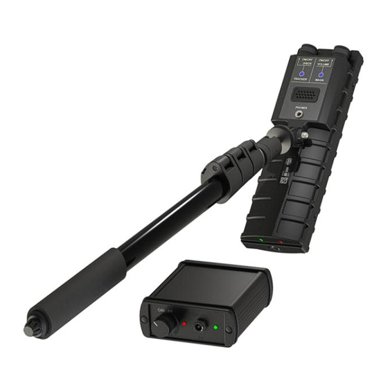
COMBINED SEARCH DEVICE ST 600, OPERATING MANUAL The numbers in fig.2 denote: 1 - switch «CABLE LOCATOR» mode and set discrimination threshold 2 - switch «MAGNETIC FIELD DETECTOR» mode and adjustment the volume 3 - cable locator turn on indicator («TRACKER») 4 - magnetic field detector turn on indicator («MAGN») -
Page 8: Telescopic Handle
COMBINED SEARCH DEVICE ST 600, OPERATING MANUAL The numbers in fig.3 denote: 1 - knob on/off and adjust the of the test signal level 2 - battery discharge indicator (red) 3 - charger socket 4 - battery charge indicator (green) -
Page 9: Power Supply
COMBINED SEARCH DEVICE ST 600, OPERATING MANUAL 5. POWER SUPPLY supply of the main unit and the generator is carried out Power from built-in batteries. Fully charged batteries ensure continuous operation of the main unit and the generator for 7 hours. The power control of the main unit is carried out using two LEDs (Fig. -
Page 10: Cable Locator Mode
COMBINED SEARCH DEVICE ST 600, OPERATING MANUAL mode is shown in fig.5 (the direction to the search object is indicated by arrows). The recommended speed of movement of the main unit relative to the object being inspected is 3-5 cm/sec. - Page 11 COMBINED SEARCH DEVICE ST 600, OPERATING MANUAL If the cable to be tested is not equipped with connectors, use the socket (fig.3, pos.6) and the probe with a «crocodile type» clip. For correct operation, the generator must be connected to the ground line (or to an extended metal structure in the room) using a cable (fig.1,...
- Page 12 COMBINED SEARCH DEVICE ST 600, OPERATING MANUAL fig.7 When tracing, depending on the orientation of the main unit relative to the search plane, the level of the signal being listened to will change. Fig. 8 shows a diagram of the change in the level of the signal being...
- Page 13 COMBINED SEARCH DEVICE ST 600, OPERATING MANUAL The signal is received simultaneously on both antennas and a differential processing mode is implemented (the difference in signal levels from both antennas is determined). When the receiver approaches the cable, the signal level received by the antenna located closer to the cable will be significantly higher than on the other antenna.
-
Page 14: Operating
COMBINED SEARCH DEVICE ST 600, OPERATING MANUAL 7. OPERATING 7.1. PREPARE TO OPERATING 1. Inspect the body of the main unit, generator and telescopic handle. Bodys must not be mechanically damaged. 2. Inspect the wires. The insulation of the wires must not be broken, the connectors must not be mechanically damaged. -
Page 15: Operating In «Magnetic Field Detector» Mode
COMBINED SEARCH DEVICE ST 600, OPERATING MANUAL 5. Adjust the position of the main unit relative to the handle. fig.12 fig.13 The hinge lock allows to change Fig. 12 shows how to tilt the main unit. the position of the main unit in any plane relative to the handle (fig.13). -
Page 16: Storage
10. WARRANTY The manufacturer undertakes during the warranty period (12 months from the date of sale) to carry out free repair of ST 600 or its replacement on condition that the customer observes the rules of operation, transportation and storage, in the absence of mechanical damage, in the... - Page 17 Russia, 192029, St. Petersburg, Obukhovskoy Oborony, 87 +7-821-412-3321, +7-812-412-4051 http://spymarket.com/ info@smersh.pro...
Need help?
Do you have a question about the ST 600 and is the answer not in the manual?
Questions and answers