Advertisement
Quick Links
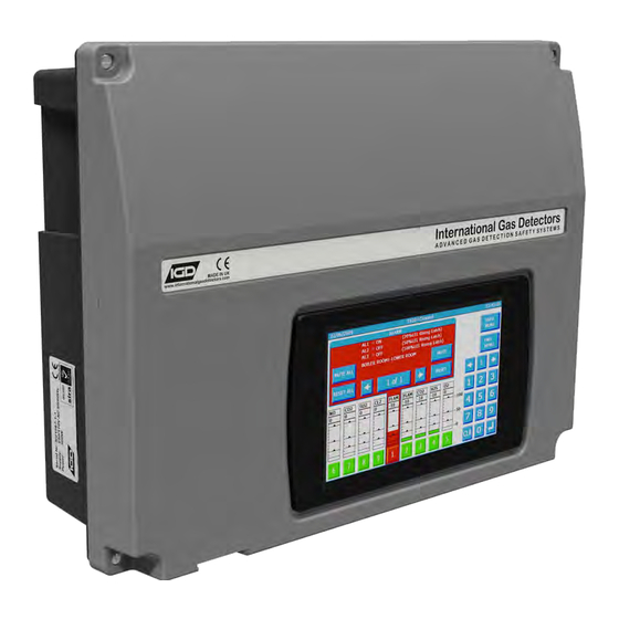
2-Wire
2-WIRE SYSTEMS
Addressable
2 - W i r e G a s D e t e c t i o n S y s t e m I n s t a l l e r s G u i d e V 4 . 5 1
Triton House
Crosby Street
T el: +44 (0)161 483 1415
Stockport
Fax: +44 (0) 161 484 2345
SK2 6SH
Email: sales@internationalgasdetectors.com
England
Website: www.internationalgasdetectors.com
EMS696504
FS646773
REF: T550-INST V4.51
Advertisement

Related Manuals for IGD 2-Wire Systems

Summary of Contents for IGD 2-Wire Systems
- Page 1 2-Wire 2-WIRE SYSTEMS Addressable 2 - W i r e G a s D e t e c t i o n S y s t e m I n s t a l l e r s G u i d e V 4 . 5 1...
- Page 2 2-WIRE GAS DETECTION Display & Analogue in Sounder Detector Digital Out 2-Wire Analogue in Addressable Detector Volt Free Digital Out Relay Output Each Detector Node Has Multiple I/O APP Based Setup and Service Tools 2 Core Cable Connects Detector Nodes No Specific Cable Type No Cable Polarity First Fit Cabling...
- Page 3 This installers guide is intended for the use of system specifiers, surveyors, designers and installers. The intention of this guide is to provide information for the correct installation of IGD’s range of 2-Wire gas detection systems. This guide indicates correct cabling practice, types of cabling which can be used and options available to correctly design and install a 2-wire gas detection system.
- Page 4 SECTION 1 MOUNTING DETAILS FOR EQUIPMENT...
- Page 5 Note that the rear case can be rotated to allow 20mm entries to face either up or down Installation Cables Supported Installation Cables 2 Core 1.5mmSQ or 2.5mmSQ See IGD Cable System Calculator Typically SWA, MICC, FP200, SY, CY, H03VVH2-F Mains Cable Screened, screened or Similar...
- Page 6 Note that the rear case can be rotated to allow 20mm entries to face either up or down Installation Cables Supported Installation Cables 2 Core 1.5mmSQ or 2.5mmSQ See IGD Cable System Calculator Typically SWA, MICC, FP200, SY, CY, H03VVH2-F Mains Cable Screened, screened or Similar...
- Page 7 GAS DETECTOR SHOWN The ATEX version uses IGD’s JB3 series ATEX EXD terminal enclosure. Please note that cable glanding and sealing must conform to ATEX requirements which is more fully described in the ATEX JB3 manual Mounting Details and Dimensions Safe Area Versions 20mm Entries Top, Bottom &...
- Page 8 Battery Backup Modules TOC-750-BAT1 7AH Battery Backup with 150W PSU 120.5mm 382mm 72mm Front Face Side Face 360mm 56.5mm 30mm 10 off 20mm 20mm Cable Entries 48.5mm Bottom Face FRONT VIEW TOC-750-BAT2 17AH Battery Backup with 300W PSU 115mm 460mm Front Face Side Face 95mm...
- Page 9 SECTION 2 SITING GAS DETECTORS...
- Page 10 Siting Gas Detectors Gas detectors usually fall into two groups for placement 1. Plant Protection. Typically flammable gas detectors fall into this category. Aside from asphyxiation flammable gases are typically not directly toxic and so detectors are placed strategically where the gas is expected to accumulate based on its relative density to air (lighter or heavier) 2.
- Page 12 It is extremely important to ensure a service plan is in place for any gas detection system installed as part of a site safety system. IGD can work with operators to provide advice, service and spares to ensure an appropriate level of cover.
- Page 13 General Detector Mounting Positions Atex (BS EN 60079-29-1) Detectors should be mounted vertically with the sensor face facing downwards to protect from contamination. General Detector Mounting Positions Safe Area (BS EN 50194) Sensor Facing Down Sensor Mounted to Vertical Wall in Various Orientations Do NOT Mount With The Sensor Facing Upwards...
- Page 14 Detectors in Airflows Mounting Positions Atex (BS EN 60079-29-1) Air Flows up to 6M/S Are Allowable Without Any Performance Issue Across the front of The Sensor Face Do NOT mount Detectors Where Airflows Are Likely to be Directed either onto or Away From the Sensor Face.
- Page 15 Standard LED beacon sounder modules are available from IGD and can be run from addressable I/O points to minimise cabling. Another option is to fit IGD’s range of annunciators.
-
Page 16: Cable Sizing
SECTION 3 GENERAL CABLING PRINCIPLES CABLE TYPES CABLE SIZING... - Page 17 Cable Type Guidance IGD’s 2-Wire gas detection systems operate using screened cabling of appropriate cross sectional area. There are no specific requirements and our typical advised cable types are indicated below. Cable screens, either foil and drain wire, braid or armouring must be continuous between devices and grounded for effective operation.
- Page 18 Main Base PCB Connectors When unplugging detectors from the main PCB DO NOT lever them off. This will potentially cause damage to the PCB and/or connector mating parts and invalidate any warranty. If it is necessary to remove the PCB connectors use long nose pliers. Note that connectors can be plugged either vertically or Horizontally to the PCB...
- Page 19 Cabling: When using stranded cable fit bootlace ferrules to prevent stray wire strands shorting. Cable glands must be used for cable entries. System Example 0-100%LEL GAS DETECTOR SN:20235-1-1 ADD:4110 2-Wire Use Annunciators For Door Addressable Entry Control. Use Annunciators with Gas Detector Interfaces to Detect &...
- Page 20 Interfacing to the Remote Modbus Port The Tocsin 750 series controllers have an in-built memory map allowing access to alarm status, panel status, readings etc using Modbus RTU protocol. Wiring between units is as follows: RS485 Modbus Comms Port Master DCS/BMS Note only the A,B and 0V DC Connections are Used.
- Page 21 L1 to L1 to L1 and L2 to L2 to L2 etc for continuity. It is necessary to fit an IGD terminator at the last device as indicated for operation of the system. In-coming and out-going screens must be connected as indicated, ensuring screening continuity.
- Page 22 Cable Sizing The total number of devices that can be supported on a cable highway will be limited by the reset fuse on the PCB, the cable length and size fitted and the power requirement for each module. The controller reset fuse is set to 2A. The following table is intended as a guide to show the number of devices that can be run taking into account the volt drop for differing cable sizes before boosters need to be employed.
- Page 23 SECTION 4 MAKING DEVICE CONNECTIONS TO DETECTOR NODES...
- Page 24 Mains Power and Controller Overview Display Option 1 (750) Display Option 2 (650/635) 7” Colour Touch Screen HMI 2 x 8 RGB LCD and Jog Wheel Hub Card PCB Common to All Assemblies. Note entry level 635 version is a part populated PCB supporting fewer detectors.
- Page 25 Mains Power and Controller Overview Controllers with mains power supplies must be fed via a unique fused spur fused at 3A. Use ferrules or 4mm fork crimps to prevent stray wire strands and potential shorting Note incoming Earth connection Earth Point for Cable Screens Incoming Panel Earth For Detector Nodes,...
- Page 26 Note that one 2-Wire addressable highway running Sentinel+ protocol can support up to 32 modules. Each module can have up to 8 connected devices. IGD Configuration software is used to configure the module PCB to switch devices on and off and set addresses (see Tocsin 650/750 Manual). If the connected devices have already been configured then the base address can be set from which all other...
- Page 27 Pellistor Port Option to Interface to MK3, MK6 or MK7 Pellistors Sounder 85dB (Option for TOC-750 Annunciators) Display 2 x 8 Programmable LCD with RGB Backlight (Option for TOC-750 Annunciators) Comm Port Supports IGD Infra-Red, PID, Toxic and Oxygen Gas Detectors...
- Page 28 Gas Detector Connection The most commonly supplied detector node comes pre-fitted with a gas detector. The detector front assembly simply plugs onto the indicated connector. Note that all detector front assemblies have a common system address. The detector node module is designed to read the data from this address and report it back to the control panel using its own ‘unique’...
- Page 29 Detector Node. 24V DC Example fit protection FOR DC LOADS diodes when switching DO NOT EXCEED external DC loads. COMM 30V DC 5A 1N4004 Diodes. For Diode Packs IGD PN: TOC-750-DIO 0V DC...
- Page 30 The Solid State Outputs Can be used to Switch LED Beacon Sounders if Required. 1 2 3 4 IN+ OUT+ It is recommended to use IGD LED Beacon Sounders Part Number 5083101 Connections Shown are for 5083101 and shown one output switching the...
- Page 31 4-20mA Off Anything Greater is On Solid State Input From TOC-10 Gas Detector The Solid State Input can be used to interface to IGD TOC-10 Series Flammable Gas Detectors. Wire as TOC-10 Unit 1 TOC-10 Unit 2 Indicated and the Input Will Read the Two Alarm Levels From the TOC-10.
- Page 32 Digital Input..Gas Meters To be able to read a digital pulse train from a gas meter volt free contact or similar it is necessary to use adaptor cable part number TOC-750-GMA. The following diagram indicates fitting the cable and field wiring to a volt free contact. Accessory Port I/O Port 2 I/O Port 1...
- Page 33 0V DC powered sensor does not 24V DC have an isolated output then 4-20mA Signal 4-20mA a separate isolator must be fitted as indicated. These may or may not require external power. The IGD Option shown is loop powered PN TOC-MA-ISO...
- Page 34 170mA 2.5V Note: The Pellistor ‘Type’ is selected using IGD service tool app or by using the setup routine in the TOC-750 Software. Once selected this automatically sets the head supply voltage. In operation and with zero air applied correctly to the detector the ‘balance’ between the two detector ‘beads’...
- Page 35 SECTION 4 Control Panel Interfaces and Connections...
- Page 36 Tocsin 650 and 750 Control Panel & New 2 Wire Hub PCB Features Rs485 Remote Ethernet (Modbus etc) Bluetooth Display Battery Connection Colour HMI For Battery Backup Display TOC-650 (2x8 LCD) Fault Relay Alarm Relay 1 Alarm Relay 2 Alarm Relay 3 Power in Inputs for E-stops/Fire 24V DC...
- Page 37 DC loads. 1N4004 Diodes are provided Relay with each module. Relay For Additional Diode Packs IGD PN: TOC-750-DIO The four relays included on the hub card can be assigned to alarm levels in the relay alarm routine. They appear on internal cable 0 during a relay FIND.
- Page 38 Panel Beacon Sounder Output The 750 hub card is fitted with two SSR outputs intended for use with Beacon Sounders. During a FIND command these will appear on cable 0 (internal to the hub card) and can be assigned to alarm levels during the alarm setup routine. Addresses will be assigned as 105 and 106 during the FIND operation.
- Page 39 Tocsin 650/750 Addressable Relay Card In all Cases: Relay contact ratings. 5A @ 250V AC Non-Inductive 5A @ 30V DC Non-Inductive Power out for 0V DC Spike suppression must be fitted use in conjunction 24V DC Note that FAULT relays are normally with relays energised on power up.
- Page 40 Relay cards also have analogue and digital inputs that can be used to read data onto the system from external devices. Setup of the inputs, type, range, addressing etc is controlled via IGD’s Android Apps. Wiring options are indicated below. Note the differences between Version 1 and 2 PCB assemblies.
-
Page 41: Important Note
Note that on the top level master panel only cable 1 and cable 2 support cascading. Hubs cards can operate without displays and can be DIN rail mounted into Cabling between panels/hubs can enclosure systems such as IGD’s range of be up to 1000M field boxes Ports not used for... - Page 42 External Battery Backup and Power Booster Modules Both the 650 and 750 series 2-Wire control panels can accommodate 5AH internal batteries for battery backup. If battery backup is required for longer time periods than the internal batteries allow then external battery backup units can be employed. Two external battery back options are available.
- Page 43 1.73 Node with 2 x 8 RGB Display 1.89 Node With MK6/7 Pellistor & 2 x 8 RGB Display 2.52 IGD Beacon Sounder (PN 5083101) Cable Dissipation 1000M 1.0mmSQ (Approximation) 4.25 Cable Dissipation 1000M 1.5mmSQ (Approximation) 2.17 Cable Dissipation 1000M 2.5mmSQ (Approximation) 1.18...
- Page 44 Booster Modules 0-100%LEL GAS DETECTOR SN:20235-1-1 ADD:4110 2-Wire Addressable Mains Power Controller in Supervisors Office Laboratory ATEX Zoned Area 0-100%LEL GAS DETECTOR SN:20235-1-1 ADD:4110 Gas Bottle Store Power Booster Cable Highway Mains Power Power boosters are used where the control panel cannot supply enough power for the installed cable system.
- Page 45 • Failure to observe the above rules may lead to non compliance with The Electricity at Work Regulations 1989 and the EMC Regulations 2006 (SI 2006/3418) July 2007 • Failure to observe the above rules may lead IGD to withdraw any terms of Warranty associated with their Gas Detection products for the specific installation concerned...
- Page 46 Typical Industrial Installation Scheme A Preferred Cable Type 2 Core FP200 Min Ceiling Height Basket Tray 1.5mmSQ, Check Cable Typically 50mm Sizing to IGD Guide Accessory Cables Typically Belden Style Security Cable 4502 FE, Foil Screen, 4 Core and Drain Wire 0.75mmSQ...
-
Page 47: Gas Alarm
Typical Room Installation Scheme B Typical of Laboratories and Similar Preferred Cable Type 2 Core FP200 Min 1.5mmSQ, Check Cable Sizing to IGD Guide Gas Detection Cabling Mounted to Existing Containment For Fire/Security System Accessory Cables Cabling Fitted to Tray... - Page 48 Note Conduit Size Large Enough Core FP200 Min For One FP200 Cable Run and 1.5mmSQ, Check Cable Accessory Cable Type 4502 FE Sizing to IGD Guide DO NOT Attempt to Enlarge 20mm Entries, This Will Invalidate Warranty and Damage Enclosure Sealing.
- Page 49 Cable Screen or Drain Wire Refer to TOC-750 Series Sampler Manual for Full Details Tubing 6 x 4 Polyurethane Other Tube Options Available Do Not Exceed 20M A variety of End of Line Termination Points Are Available Contact IGD For Further Details...
- Page 50 Installation Requirements for No-Volt Release Modules No Volt-Release modules are fitted in situations where user intervention is required after resetting a gas alarm before a signal is re-instated. An example of its use would be where an output from the gas detection system is being used to control a gas supply to a process.
- Page 51 Notes...
- Page 52 International Gas Detectors Ltd Triton House Crosby Street Stockport Manchester United Kingdom SK2 6SH Tel: +44 (0)161 483 1415 E-mail: sales@internationalgasdetectors.com Website: www.internationalgasdetectors.com...
Need help?
Do you have a question about the 2-Wire Systems and is the answer not in the manual?
Questions and answers