Table of Contents
Advertisement
Operation and Maintenance Manual
®
HydroDOS
Chlorine Dioxide System
Serial number:
.................................
Hydrotec (UK) Ltd
Hydrotec House
5 Manor Courtyard, Hughenden Avenue
High Wycombe, Bucks HP13 5RE
Tel: 01494 796 040
email: services@hydrotec.co.uk
Last change 04/2016 E-P – AL/TW/PW | Subject to technical modifications
I-1/103
Advertisement
Table of Contents

Related Manuals for Hydrotec HydroDOS HD550G

Summary of Contents for Hydrotec HydroDOS HD550G
- Page 1 Operation and Maintenance Manual ® HydroDOS Chlorine Dioxide System Serial number: ......... Hydrotec (UK) Ltd Hydrotec House 5 Manor Courtyard, Hughenden Avenue High Wycombe, Bucks HP13 5RE Tel: 01494 796 040 email: services@hydrotec.co.uk Last change 04/2016 E-P – AL/TW/PW | Subject to technical modifications...
- Page 2 INDEX The index shows the individual chapters. Detailed information about the individual chapters is shown on the corresponding cover sheets. Preface Chapter General information Transport and storage – Chlorine dioxide system Chapter Chapter Description / Technical Data Chapter Installation and assembly Chapter Operation dosing pumps Chapter...
- Page 3 For any further information or if you are confronted with any problems, please contact our services department. Contact address Hydrotec (UK) Ltd Hydrotec House 5 Manor Courtyard, Hughenden Avenue High Wycombe, Bucks HP13 5RE Tel: 01494 796 040 email: services@hydrotec.co.uk...
- Page 4 – General information Chapter Page Structure of manual Safety information General safety information Operator’s duty of care Appropriate use Basic safety measures Maintenance, repair and electric work Start up after maintenance and repair work Environmental regulations Risk in the event of safety instructions being disregarded Operational and auxiliary materials Special safety information for chlorine dioxide units Operator...
- Page 5 For information about the chapter contents see index on page 1 of each chapter. For any additional information or problems encountered in conjunction with operation, please contact our Services Department at the following address: Hydrotec (UK) Ltd Hydrotec House 5 Manor Courtyard, Hughenden Avenue...
- Page 6 Minimum PPE signs: Wear eye protection! Wear protection gloves! Wear protective clothing! Notes: Tips and additional information to make work easier for efficient operation. 2.2 Operator’s duty of care The system is constructed and manufactured with respect to and in consideration of all current standards as well as further technical specifications, and has the latest state-of-the-art technology, allowing for maximum safety under all operating conditions.
- Page 7 2.3 Appropriate use Important! Any other use of the system, other than described, is deemed to be not in accordance with the specification. The manufacturer / supplier will not accept any liability resulting from the improper use of the system. Such risks are borne by the operator. All regulations and instructions in the operating and maintenance manual and applicable local regulations must be strictly adhered to.
- Page 8 Maintenance, repair and electrical work - All inspection and maintenance intervals specified in the operation and maintenance manual must be adhered to. - Prior to any work, the system must be disconnected from mains. - The system is to be de-pressurized and shall be protected from accidental re-start. - Only suitable and correctly functioning load-supporting devices shall be used when replacing heavy components or system elements.
- Page 9 2.5 Risks in the event of safety instructions being disregarded The consequences of disregarding safety instructions can be dangerous to the system, material and personnel. This will also invalidate any warranty claims. We shall not accept liability for water damage caused due to disregard of the safety instructions! 2.6 Operational and Ancillary Materials Safety datasheets:...
- Page 10 Special risk - Chlorine dioxide spills should not be removed with tissues! There is a self-ignition risk with dry tissue and chemical residue! - Overpressure can be applied to the plant components! Risk of injury and material damage from flowing water and sudden pressure release of components! All pressure pipes must be inspected at regular intervals! - The use of chemicals with an excessive concentration or mistaking of chemical...
- Page 11 The warranty period for the system is 12 months, calculated from either the date of commissioning by Hydrotec (UK) Ltd, 15 months from the date of supply or in the event that commissioning is not included with the supply agreement, whichever is the shorter. The plant must be operated and maintained in accordance with Hydrotec (UK) Ltd’s requirements.
- Page 12 - Transport and Storage – Chlorine Dioxide Unit Chapter The shipping weight (see table “Technical Data” in chapter ) is the net weight of the total plant. The plant shall be shipped empty! Appropriate measures must be taken to avoid any damage during transport. The entire delivery must be checked for completeness and possible transport damage immediately upon receipt at the warehouse/site.
- Page 13 – System description / Technical Data Chapter Page System description General Function Water pressure Demand on water connection Technical Data Technical Data – Chlorine dioxide system Installation schematic Scope of supply Components - Installation cabinet - Reactor cabinet - Chlorine dioxide reactor - Dosing pumps - Chemical collection tubs - Polymer piston water meter with communication module...
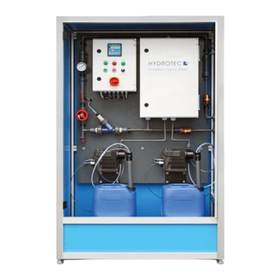
- Page 14 1. System description 1.1 General Ill. 1 ® The HydroDOS system is designed as a cabinet system and is used for the production of chlorine dioxide. A chlorine dioxide solution is automatically produced from the chemicals hydrochloric acid (9%) and sodium chlorite (7.5%). Both reactants are mixed in a reactor chamber so that a solution with a maximum concentration of 20 g/l is available for dosing.
- Page 15 Process The chlorine dioxide disinfection process uses the strong reactivity of the chlorine dioxide gas, whereby the gas can kill all types of germs and virus almost totally. Chlorine dioxide is more efficient than disinfection by means of chlorine. Since chlorine dioxide is a gaseous and instable material, production for stock is not possible.
- Page 16 1.2 Function ® HydroDOS system is suited for the production of chlorine dioxide situated in a plant cabinet with a transparent door for visual control of plant. All of the plant components are installed on a back plate. The chlorine dioxide is produced in the reactor vessel that is housed in a separate reactor Ill.
- Page 17 1.3 Water pressure In order to guarantee optimum and economic operation of the system, the water pressure should be adjusted to between 2.0 – 6.0 bar. The water pressure should not fall below 2.0 bar in order not to impair the functional performance of the system.
- Page 18 2. Technical Data 2.1 Technical Data – Chlorine dioxide production system ® Type HYDRO DOS HD 550G Water feed (input) DN 15 Water feed (output) DN 15 ¼” (hose connection) Discharge connection Mains electrical connection 230 V / 50 Hz AC Min./max.
- Page 19 2.2 Installation schematics Last change 04/2016 E-P – AL/TW/PW | Subject to technical modifications I-19/103...
- Page 20 3. Scope of supply 3.1 Components Ill. 3 1 = Control box 2 = Reactor cabinet 3 = Plant input (DN 15) 4 = Plant output (DN 15) 5 = Dosing pump with intake lance for sodium chlorite 6 = Tub for sodium chlorite (NaClO - 7.5 %), positioned in a collection tank 7 = Dosing pump with intake lance for...
- Page 21 Reactor cabinet Suited for the installation of the chlorine dioxide reactor; lockable, protection type IP 66 Material: Polyester Dimensions: Width 400 mm Height 600 mm Depth 230 mm Quantity: Including ventilation unit for odour neutralizing, carbon fibre filter mats at input and output. Chlorine dioxide reactor Reaction chamber used for the production of chlorine dioxide from the chemicals hydrochloric acid and sodium...
- Page 22 Chemical collection tanks 2 Euro tanks used for separate installation of chemical tubs during operation. Material: Dimensions (L x W x H): 400 x 300 x 320 mm Polymer piston water meter with Used for monitoring of flow rate in the drinking water ring communication module line.
- Page 23 Chlorine dioxide control Measuring control unit (Neon controller) for monitoring of chlorine dioxide concentration in water supply, mounted Ill. 9 in the control cabinet of the system. Dimensions: 144x144x83 mm Material: Weight: 0.6 kg Protection class: IP 54 Power consumption: 10 VA Quantity: Control cabinet Suited for the installation of the control unit to monitor the...
- Page 24 3.2 Accessories Hydrochloric acid (HCl) Chemical used for the production of chlorine dioxide Concentration: 9 % (purity as per DIN EN 939) Tub volume: 25 litres Sodium chlorite solution (NaClO Chemical used for the production of chlorine dioxide Concentration: 7.5 % (purity as per DIN EN 938) Tub volume: 25 litres Neutralising agent...
- Page 25 – Installation and Assembly Chapter Page General information Installation site Pre-assembly Control of shipment Input and output lines Other preparation Use of chemicals Hydraulic connections Installation input / output Wash and discharge connection Electric connections Mains connection Control External water meter Volt-free contact External circulation pump Last change 04/2016 E-P –...
- Page 26 1. General information ® The HydroDOS chlorine dioxide disinfection system has been designed to be housed in an enclosure. The individual components are mounted to a plate and connected to each other. The system shall be integrated and connection to the local installation. ➢...
- Page 27 ® Installation example HydroDOS Chlorine dioxide disinfection plant: Ill. 1 Split Compartment Tank Installation Last change 04/2016 E-P – AL/TW/PW | Subject to technical modifications I-27/103...
- Page 28 Ill. 2 Single Compartment Tank Installation Last change 04/2016 E-P – AL/TW/PW | Subject to technical modifications I-28/103...
- Page 29 2. Installation site The below must be understood and guaranteed during the installation of the chlorine dioxide production system. The minimum installation dimensions are shown in the dimensional sketch and table (see chapter III). • Installation of chlorine dioxide disinfection system in a separate, frost-proof and well ventilated room.
- Page 30 3. Pre-assembly Control of shipment The delivery shall be checked for completeness and possible transport damage prior to installation and assembly. Any issues must be recorded immediately. Input and output pipe Input and output pipes shall be provided to the unit in the required positions.
- Page 31 The pipe layout inside the unit is designed as a ring Ill. 5 pipe. The flow direction must be checked when being installed to a water supply! The unit must be operated in one direction only. Should the unit be installed backwards, the non-return valves will stop the flow.
- Page 32 5. Electric connections Mains connection Connection: 230 V / 50 Hz Connection cable: 3 x 1.5 mm² The 2 m long connection cable is prepared for the local connection and reaches outside the unit. This cable is to be installed in a switchable fused spur (with a 5a fuse). Control Ill.
- Page 33 The plant can be controlled via a local external water meter with a pulse ratio of K =1 or K = 10 (Can be supplied by Hydrotec). The electronic and PLC connections are already provided. A 2 m long connection cable reaching to the outside of the cabinet is also provided.
- Page 34 Chapter Operation dosing pumps Page General information Construction Pump connections Intake lance Technical Data Installation of dosing pump Base plate Connection of intake and pressure pipe Connection overflow and ventilation Electrical connections Connection schematics and connector engagement Control unit – operation Control and monitor elements Functional levels pump control Start-up of dosing pump...
- Page 35 1. General information ® HydroDOS SMT 6.0-B1 dosing pump with step index drive and electronic performance adjustment. Control is in an easy menu structure via display. The pump is suited for indoor installation only. Additional use or the operation of pumps under ambient and operational conditions not authorized is improper use and will invalidate any warranties.
- Page 36 3. Technical Data Connections Max. intake height 2.0 m Max. length of intake line Max. pre-pressure suction side 2 bar Min. counter pressure at pressure nozzle of pump 1 bar Max. counter pressure 10 bar Noise level 60 dB (A) Ambient temperature 0 °C bis +40 °C Protection type (with mains plug)
- Page 37 4. Installation of dosing pump The pump must be mounted on an even surface and freely accessible for operation and maintenance work. Caution! The screws must be tightened carefully, otherwise the plastic casing will be damaged. Dosing pump on support Ill.
- Page 38 5. Electrical connections Caution! Electrical connections must be made by qualified experts only! The mains supply must be switched-off prior to connecting the mains supply and relay contacts! The pump casing may only be opened by authorized experts only! Connection schematics and connector engagement Ill.
- Page 39 Last change 04/2016 E-P – AL/TW/PW | Subject to technical modifications I-39/103...
- Page 40 6. Control unit – operation Control and monitoring elements Display-Test This is automatically carried out when the dosing pump is started. All display segments are switched on for 3 seconds and the software version is shown on the display for 2 seconds. Operating state The dosing pump is started or stopped by the respective Start/Stop button.
- Page 41 Functional levels pump control Functional level “OPERATION” Suited to select and adjust the pump operation modes (manual, contact, analogue). Pump is dosing the set capacity (l/h or ml/h). Setting is done via the operator wheel. Pump is dosing the set volume (ml/contact). Setting is done via the operator wheel.
- Page 42 7. Start-up of dosing pump Control prior start-up - Check all connections for proper fit and re-tight on request. - Check if the fixing screws of the dosing head are tightened with 2.1 Nm torsion moment and re-tighten on request. - Check if all electrical connections are correct.
- Page 43 Calibration Last change 04/2016 E-P – AL/TW/PW | Subject to technical modifications I-43/103...
- Page 44 8. Failure remedy Failure Reason Remedy Pump not running No mains supply Connect mains supply False mains supply Stop pump and check voltage and motor. The pump must be returned to us if the pump motor fails. Electric breakdown The pump must be returned to us for repair.
- Page 45 Failure Reason Remedy Dosing capacity of Dosing head not de-aired Repeat de-airing pump not exact totally Out gassing material Check installation Valves partly contaminated or Clean valves crusted False monitoring of dosing Calibrate capacity Counter pressure fluctuations Installation of a pressure hold valve and pulsation damper (muffler) Intake height fluctuations...
- Page 46 9. Putting dosing pump out of operation. This must only be carried out if the pump must be dismounted or replaced. Caution! - Chemicals must always be stored carefully in separate tubs! - Protective clothing must be worn when working at the dosing head, the connections or connection lines (protective glasses and protective gloves)! ➢...
- Page 47 – Chlorine dioxide measuring / control Chapter Page General information Construction and function Components measuring instrument Probe cleaning Operation Calibration Dismounting of measuring probe Last change 04/2016 E-P – AL/TW/PW | Subject to technical modifications I-47/103...
- Page 48 1. General information The installation fitting to support the measuring electrode is installed in the input side of the drinking water ring line. An evaluation of the measured values is carried out by the measuring and regulating device installed in the control board. (Control unit see chapter VII) Caution! Maintenance and operation of plant may be carried out by skilled...
- Page 49 Probe cleaning If contamination cannot be removed by the automatic probe cleaning, it will be necessary to clean the metal surface of the electrodes regularly. A standard cleaning agent is recommended, and must be flushed off carefully with water after cleaning. The setting of the correct measuring value can take some time after cleaning.
- Page 50 5. Dismounting of measuring probe 1 = Measuring fitting Ill. 2 2 = Membrane valve 3 = Discharge ball cock A = Screw connection cable B = Screw measuring fitting C = Insert nozzle The plant must be switched-off by pressing the button “Off” on the control board and the switch moved to the off position.
- Page 51 Chapter Electronic Control Page General information Indicating elements in control board Control Terminal plan control unit Measuring and control device chlorine dioxide General Technical Data Connection plan chlorine dioxide measuring instrument Operation Setting of parameters Control settings Setting of measuring instrument Calibrating Automatic sensor cleaning (ASC) Determine average...
- Page 52 1. General information ® The control that monitors and regulates all operating states of the HydroDOS chlorine dioxide system is accommodated in a separate cabinet inside the unit. The below components are connected: ➢ Dosing pumps for hydrochloric acid (HCl) and sodium chloride solution (NaClO ➢...
- Page 53 3. Control (in switchboard) Ill. 2 A PLC control is installed in the switchboard. The PLC includes an integrated display and operation buttons. The below information can be retrieved on the display: Operation Operation hours Time interval to next maintenance Software version Extended failure diagnosis (see menu point 4.8)
- Page 54 Caution! The operation parameters can be retrieved by an authorized electronic expert or our service staff only, due to mains voltage being applied. Safety regulations must be observed. For that purpose, the control must have mains voltage applied. Any national safety regulations must be followed!!! Work on the control and cables must be carried out by authorized electrical experts only.
- Page 55 3.1 Terminal plan control unit BMS Connection terminals: 26 – NC (normally closed) 27- Common 28 – NO (Normally open) Last change 04/2016 E-P – AL/TW/PW | Subject to technical modifications I-55/103...
- Page 56 There is no control for setting failures, system failures and handling failures! Setting of operation parameters and programming may be carried out by Hydrotec staff only. 4.1 Technical Data A measuring instrument to control the chlorine dioxide content is installed in the switchboard:...
- Page 57 4.2 Connection plan chlorine dioxide measuring device (switchboard) Connection Terminals Notes 1 – 4 Sensor with bright 1 = shielding (protection) metal electrodes 2 = measuring electrode = brown 3 = reference electrode = white 4 = counter electrode = blue 3+4 to be bridged in case of 2-electrode- sensors Pt 100...
- Page 58 4.3 Operation Touch panel Ill. 3 The touch display is used by pressing the screen. Because of its resistive touch screen the touch panel can be operated with gloves. Display Display monitoring Ill. 4 1 = Device name 2 = Display of measured value chlorine dioxide 3 = Time 4 = Event messages 5= Display of temperature...
- Page 59 Main menu You can access the main menu from the desktop by pressing the Down Arrow Key at the bottom left corner (point 7 on picture 4). In main menu you can access all submenus just by pressing the symbols. Ill.
- Page 60 Setting of figure parameters A keyboard opens for parameters where you can freely enter value figures or texts if you tap on the input screen. In case of a letter keyboard you can choose the subsequent letters by pressing the corresponding key several times.
- Page 61 ➢ Controller o S1 controller Adjusting of control parameters for setpoint 1 o S1 configuration Adjusting of output parameters for setpoint 1 o S2 controller Adjusting of control parameters for setpoint 2 o S2 configuration Adjusting of output parameters for setpoint 2 o Relay ON/OFF and direction of control of relays o Times...
- Page 62 Note: You can choose from different languages for communication with the system. The language is already set ex works for the corresponding operating site (country). The categories shaded in grey (fields) can be purchased on request (add-ons). 4.5 Adjustment of measuring instrument Calibration Measuring by the chlorine dioxide sensor is dependent on flow.
- Page 63 Automatic sensor cleaning (ASC) A cleaning of the metal surface of the sensor is carried out in adjustable intervals. Any deposits on the sensor (scale, oil film, manganese) are removed electro-chemically so that the sensor always has a clean electrode surface. These settings are pre-set. Particularities during - The cleaning process takes ca.
- Page 64 4.6 Setting of controller / limit values Controller settings, controller parameter and limit values must only be carried out by our service staff. The settings are shown in the commissioning record. Caution! Operation settings and programming is to be carried out by experts only. Any illegal operation of the control may result in operation states, damage to the control and risk for life and limb beyond control! Any warranty claims are excluded in such case.
- Page 65 4.7 Failure records Record Possible reason Action Inclination failure The inclination determined at - Check connections and flow and repeat calibration was <20%. calibration - Clean/replace electrode of probe - Monitoring 0 or 500 mV: check mains voltage Contact our service staff! Failure input 1 Signal failure at input 1 - Control cable and connection of...
- Page 66 4.8. Extended failure diagnosis PLC-control in switchboard Record Possible reason Action Fault Too low or even no water flow Provide water flow Water flow Stop valves closed or Replacement of pumps or valves, on request circulation pump not in operation Fault Internal failure of dosing Check dosing pumps...
- Page 67 – Start up (commissioning) / Putting out of operation VIII Index Chapter Page Examination prior to start up ® Start-up of HydroDOS Chlorine dioxide unit Preparation Start Filling and de-airing of dosing pumps Filling of system Calibration (gauging) of dosing pumps Placing of chemical tub Installation of intake lances Putting plant control out of operation...
- Page 68 1. Examination prior to start up ® HydroDOS chlorine dioxide disinfection system designed to be housed in a board. The individual components and pipes are pre-mounted. Control installed and programmed ex works. All items listed below shall be examined prior to start up: Hydraulic connections Are the following pipes connected correctly and have these been checked for tightness? (see tags!)
- Page 69 Electric connections / - Is the electrical connection on the control unit connected Control lines correctly and a permanent voltage guaranteed? - Is the impulse cable of the chlorine dioxide electrode connected to the chlorine dioxide measuring instrument? - Is it guaranteed that all electric consumers (dosing pumps / fans) are supplied with voltage? - All control lines (dosing pumps / intake lances / water meter) must be connected to the control unit...
- Page 70 Feed water pressure The feed water pressure shall not exceed or fall below the following values: Min. pressure: 2.0 bar (flow pressure) Max. pressure: 6.0 bar (static pressure) Control unit settings - Standard setting - code and language. - Setting of measuring unit – gauging, average cleaning interval.
- Page 71 ® 2. Start-up / commissioning of HydroDOS Chlorine dioxide plant Skilled experts only are entitled to carry out commissioning. It is recommended, to instruct our service staff for such work. Important! The correct sequence for commissioning shall be guaranteed. Highly-explosive air chlorine dioxide mixture may be formed if the dosing process is started prior to the reactor vessel being filled with water.
- Page 72 2.2. Switch on Apply voltage to plant: ➢ Put main switch to position “ON” (mains connection III. 2 activated). The LED “POWER” lights on. ➢ Put selector switch to position “0” Push button “ON” The LED “OPERATION” lights on ➢ Display monitoring at control: III.
- Page 73 2.4. Filling of plant Requirements: - Ball cock at plant outlet open. - Discharge to drain has to be opened. - Stop fittings to consumer (outlet side) have to be closed. - The intake lances have to be immersed into the water tubs. - The dosing pumps still dose from the drinking water tub.
- Page 74 2.5. Calibration of dosing pumps The dosing pumps are provided with a display for dosing efficiency that is adjusted ex works to an operation pressure of 3 bar. The pump capacity can be set to the actual operation parameters by calibration. A measuring cylinder is required for the purpose of calibration.
- Page 75 2.7. Installation of intake Requirement: lances The chemical tubs are put into respective chemical collection tanks. ------------------------------------------------------------------------------------- Caution! Protective clothing shall be worn whilst the chemical tubs are connected! III. 5 The following has to be done in respect of the chemical tubs: a) The chemical tub lid shall be removed and to be kept to close the empty tub.
- Page 76 a) The main switch must initially be put in position “ON” – LED 2.8 Plant control to be put in “POWER” lights – if the plant is stopped and switched off totally. operation AFTER A MAINS POWER CUT THE SITE OPERATIVE MUST MANUALLY PUT THE UNIT INTO OPERATION BY PRESSING “ON”...
- Page 77 Caution! It is to be guaranteed that the plant board is kept closed whilst in operation! The control box and reactor board doors shall be opened by authorized personnel only for repair and maintenance work! 3. Commissioning record Attached to the O&M is a commissioning and instruction record (see annex 3). Such record has to be duly filled by the service staff after commissioning and start up.
- Page 78 4. Replacement of chemical tub Lack of chemicals is shown by the empty record of the chemical tubs. Display: Colour: Green; the pumps function and dosing properly. Colour: Orange; Preliminary empty record. The chemical tub shall be replaced as soon as possible. Colour: Red;...
- Page 79 5. Putting out of operation / Flushing of chlorine dioxide production plant Caution! Protective clothing as per the actual valid accident prevention rules has to be worn for all work at the plant! 5.1 Short-term operational interruption No special measurements are required for short-term operational interruptions of ca. 1 to 2 hours! - The plant must be switched off with button “OFF”, LED “FAILURE”...
- Page 80 - The plant is switched-off with the “OFF” button; LED “FAILURE” Switch-off plant lights. - The selector switch has to be put in “0” position. Flush water tub with drinking 2 tubs each with a volume of 10 litres shall be filled with ca. 5 water to be provided litres drinking water Intake lances / chemical tubs...
- Page 81 Neutralizing The flushed water is collected and neutralized in the neutralizing tub. The feed water containing residual chemical traces can be well mixed (plastic hand mixer) with the neutralizing agent. Discharge into drain The concentration of the neutralized water must be controlled by means of a chlorine dioxide measuring kit prior to discharge into drain.
- Page 82 Caution! It is a must that the plant is flushed and discharged as above if opened or within the course of reconstruction measurement. If the plant has been out of operation for a longer time, also for maintenance, repair and reconstruction, a re-start according point 2 is necessary! Such work shall be carried out by our service staff or authorized and skilled experts only.
-
Page 83: Table Of Contents
– Control and maintenance Index chapter Page General information Control to be carried out by the operator (inspection) Control of ClO content Volume flow Operation pressure Filling level chemical tub Operational display control unit Check for possible plant leakage Control of external units Maintenance Inspection work whilst maintenance Contact address service... -
Page 84: General Information
1. General information ® HydroDOS chlorine dioxide production system is designed so that the operation process meets the maximum quality demands. Due to the handling with chemicals used for the production of chlorine dioxide, some plant components are mechanically and chemically stressed. In order to guarantee a correct operation, regular control inspection is therefore, a must. -
Page 85: Control Of Clo 2 Content
Control ClO -content Quick determination with chlorine dioxide measuring instrument that can be used within a measuring range of 0.05 to 0.5 mg/l ClO Compare with display on control unit. Check flow measure – a flow of 200 l/h must be set. The value Volume flow must be adjusted by means of the membrane valve if there is any deviation. -
Page 86: Maintenance
3. Maintenance ® DIN 1988 part 8/UVV chlorination prescribes maintenance of the HydroDOS chlorine dioxide production system after 6 months. A visual inspection of the plant for possible damage and leakage as well as a check of technical function of individual plant components is necessary. Caution! All maintenance and repair work at the plant must be carried out by our service staff or an authorized expert only! -
Page 87: Contact Address Service
3.1 Inspection during maintenance Dosing pumps - The intake and pressure pipes must be checked for leakage. - Check intake and pressure valves for contamination and possible leakage (power decrease of pump refer to contamination). The valves are dismounted, cleaned and faulty components replaced. - Page 88 Please bear in mind that the annual maintenance should either be carried out by Hydrotec (UK) Ltd or by an authorised specialist company since otherwise we cannot accept any warranty claim. For queries regarding operation and handling of softener, please contact our service ...
- Page 89 Appendices 1: ® Installation schematics HYDRO DOS Chlorine dioxide system 1. Schematics plant cabinet Last change 04/2016 E-P – AL/TW/PW | Subject to technical modifications I-89/103...
- Page 90 Appendices 2: Calculation chlorine dioxide production Such calculations are for the use of the below chemicals: ➢ Hydrochloric acid (HCl) ➢ Sodium chlorite (NaCLO 7.5 % Setting dosing pumps Contact (ml/Contact) K-factor water meter x chlorine dioxide nominal concentr. (K/litre) (ppm) _________________________________________________ Example:...
- Page 91 Appendices 3: Start-up and Instruction Record ® HYDRO DOS Chlorine dioxide production system Serial number: ________________________________________ Customer: ________________________________________ ◼ Temperature feed (mains) water: ________________ °C ◼ Plant pressure: ________________ bar ◼ Volume flow: ________________ l/min ◼ -content (input) ________________ mg/l ◼...
- Page 92 Plant parameters ◼ Plant type: ________________________________________ ◼ Material connection pipe: ________________________________________ ◼ Water meter (external): ________________________________________ ◼ Alarm output (safety horn/BMS): ________________________________________ ◼ Volume drinking water tank (external): ______________________________m³ ◼ Frequency for electric connection: ______________________________ Chemicals ◼ Hydrochloric acid (HCl) – 9 %: ...
- Page 93 Control type ◼ Water meter ◼ Sensor control Calibration ◼ DPD calibrating ____________________________ ppm ◼ Steepness ____________________________ mV Temperature ◼ Temperature compensation manual / 25 °C ◼ Temperature correction ___________________ °C Limit values ◼ Top limit value – LW 1 ____________________________ ppm ◼...
- Page 94 Controller parameter ◼ Pulse frequency S1 / Sensor ___________________ Imp / h ◼ Pulse frequency S2 / water meter 0 Imp / h ◼ Efficiency direction S1 /Sensor lifting ◼ Efficiency direction S2 / water meter lowering lifting Switch-on delay ◼...
- Page 95 ® Log book HYDRO DOS Chlorine dioxide production system Site: ______________________________________________________________ Time period: ______________________________________________________________ Date Chlorine Volume Operation Water Storage Storage Signed dioxide flow (l/h) pressure meter hydrochloric sodium measuring (bar) count acid chlorite value (mg/l) (m³) (ltrs) (ltrs) Last change 04/2016 E-P – AL/TW/PW | Subject to technical modifications I-95/103...
- Page 96 ® Log book HYDRO DOS Chlorine dioxide production system Site: ______________________________________________________________ Time period: ______________________________________________________________ Date Chlorine Volume Operation Water Storage Storage Signed dioxide flow (l/h) pressure meter hydrochloric sodium measuring (bar) count acid chlorite value (mg/l) (m³) (ltrs) (ltrs) Last change 04/2016 E-P – AL/TW/PW | Subject to technical modifications I-96/103...
- Page 97 Appendices 5 – Behaviour in emergency case All general safety regulations as well as the rules in view of the behaviour in an emergency case must be regarded when handling with chlorine dioxide. Emergency telephone: - Fire brigade: ......- Emergency office toxic substances ......
- Page 98 Technical documents Last change 04/2016 E-P – AL/TW/PW | Subject to technical modifications I-98/103...
- Page 99 Volume flow distribution chlorine dioxide systems Hydrotec (UK) Ltd Hydrotec House 5 Manor Courtyard, Hughenden Avenue High Wycombe, Bucks HP13 5RE Tel: 01494 796 040 email: services@hydrotec.co.uk Last change 04/2016 E-P – AL/TW/PW | Subject to technical modifications I-99/103...
- Page 100 1. Use The volume flow distribution is suitable for the chlorine dioxide system to distribute the drinking water treated with chlorine dioxide in two different pipeline systems. 2. Scope of supply Volume flow distribution 1 = Input Nominal size: DN15 Material: PVC-U 2 = Connection piping...
- Page 101 3. Function The chlorine dioxide system provides at the system outlet a drinking water mixture mixed with a chlorine dioxide solution. The volume flow distribution is already mounted at the chlorine dioxide system and the medium find its way into the volume flow distribution via support of a connection piping. The volume flow distribution enables a distribution of the drinking water with chlorine dioxide into separate piping networks or storage tanks.
- Page 102 4. Installation drawing Last change 04/2016 E-P – AL/TW/PW | Subject to technical modifications I-102/103...
- Page 103 E-P – AL / TW / PW / kb All rights reserved! © 04/2016 by HYDROTEC Subject to technical modification! All information, dimensions and sketches correspond to the latest state of technique at date of that document. Modifications that suit the technical progress and development of the product are reserved.
Need help?
Do you have a question about the HydroDOS HD550G and is the answer not in the manual?
Questions and answers