
Summary of Contents for Integra French Fry SARATOGA
- Page 1 French Fry Saratoga Vending Machine Instruction Manual Integra d.o.o. Trg kralja Tomislava 4 42000 Varaždin Croatia Copyright © 12-18...
-
Page 2: Table Of Contents
French fry machine Saratoga Manual Table of Contents INTRODUCTION .............................. 3 SPECIFICATIONS ............................... 4 SARATOGA MACHINE FRONT PICTURE ....................... 5 SARATOGA REFRIGERATION UNIT INTERNAL PARTS ................7 FRYING UNIT INSIDE PARTS (FRONT VIEW) ....................8 FRONT RIGHT MACHINE UNIT – SIDE VIEW ....................9 MACHINE INSIDE PARTS (REAR VIEW) ...................... - Page 3 This documentation is copyright protected. All rights, including those of photographic reproduction, duplication and distribution by particular methods, wholly or partially as well as substantive and technical changes are reserved. All documentation specifications can hold a error of not correct data. Company Integra is not responsible for these misunderstanding errors.
-
Page 4: Specifications
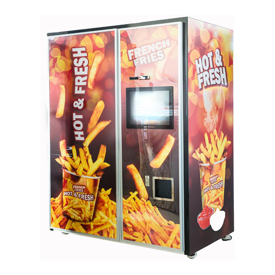
French fry machine Saratoga Setup Guide SPECIFICATIONS Height – 2000mm (78.74 inch) Dimensions Width – 1487mm (58.54 inch) Depth – 840mm (33.07 inch) 608 kg (1119lb) ± 1% Weight Internal 30 liter tank – Oil type: Sunflower oil or any fry Frying oil requirements oil to max 210°... - Page 5 Picture 1: Front side of machine 1 – Machine left door (with graphic / LED backlight) 2 – Machine right door (with graphic / LED backlight) 3 – Coin return exit 4 – Cups delivery lifting door 5 – 19'' touch screen display 6 –...
- Page 6 Picture 2: Front side internal parts 1 – Wheels 8 – Coin changer 2 – Oil tank 9 – Bill acceptor 3 – Air compressor 10 – Cup dispenser 4 – Frying unit exit 11 – Frying unit 5 – Cup transport system 12 –...
- Page 7 Picture 3: Freezer internal parts 1 – Frozen French fry storage space 6 – Air cylinder (Exit plunger) 2 – Sprocket with chain 7 – Weighting platform 3 – Dosing screw drive motor 8 – Freezer weight scale system 4 – Second freezer motor 9 –...
- Page 8 Picture 4: Frying unit internal parts 1 – Big fryer basket 8 – Buffer 2 – Small fryer system 9 – Light bulb 3 – Big fryer system 10 – Buffer brush 4 – Exit door 11 – Small fryer basket lift motor 5 –...
- Page 9 Picture 4: Right side view 1 – Central unit door 5 – French fry exit assembly 2 – Salt dispenser box (pneumatic) 6 – Weight scale system 3 – Sauce dispenser 7 – Cup dispenser 4 – Waste fries box...
-
Page 10: Machine Inside Parts (Rear View)
MACHINE INSIDE PARTS (REAR VIEW) Picture 5: Rear view internal parts 1 – Small basket position sensors 8 – Oil pumps 2 – Small lift counter weight 9 – Big lift counter weight 3 – Buffer lift pneumatic cylinder 10 – Pneumatic block valve 4 –... - Page 11 User emergency switch is used in emergency situation, this breaker cuts power to all internal components Picture 6: Emergency switch Circuit Breaker and Fuses. If any fuse trips and cannot be reset, or if a fuse repeatedly blows, contact a field service representative. Circuit breaker is main power of the machine and security in emergency cases.
- Page 12 The tools required for setting up machines: 200g weight, tools for horizontal install machine position label. These tools are not included! UNPACK AND INSPECT. 1. Carefully remove the machine from shipping protection and place it on a straight surface. 2. Inspect the outside of the machine for dents, scratches, or any other damage resulting from improper transport.
- Page 13 This machine is intended for indoor use or outdoor with rain, snow protection. Please don't install direct to sun. CAUTION Make sure the machine is properly leveled and secure on a flat, solid and stable floor or a base foundation. IF IT IS NOT DONE CORRECT, PERSONAL INJURY AND/OR DAMAGE TO EQUIPMENT MAY RESULT! 1.
- Page 14 6. Open the door of the central unit 6.1. Pull the big fryer basket counter weight and check if it can move freely on big fryer rails. 6.2. Pull the small fryer basket counter weight and check if it can move freely on small fryer rails.
- Page 15 11.3. Place 200g weight on scale 11.4. Press Calibrate scale 11.5. Press „Display weight“ ±5) grams, and 0 (+5) grams when weight is removed, the scale works If scale is showing 200( fine. Picture 8: Freezer and buffer scale calibration 12.
- Page 16 12.2. In oil section in machine program are buttons for oil filling. You can start both big and oil pump on at the same time. Press buttons „Big oil pump on“ and „Small oil pump on“ and fill frying units with oil up to marked level (pic. 5). We recommend for initial filling to fill oil up to maximum level.
- Page 17 change after certaing amount of big fryings. Note that recomended settings are already displayed and saved and you can revert to them simply by pressing „Reset to default“ button. Picture 11: Fry settings menu After you saved your bake settings, press Exit and go to Price/Buffer settings. ...
- Page 18 everything from buffer and start to fry again if it's needed. Machine decides wheter it should fry fries based on number of fries in buffer you decided you want to have at that time. Picture 12: Price/Buffer Once you set up machine, „Customer mode on startup“ should be checked because if machine loses it's power supply and than it comes back again, machine will start customer mode automatically.
- Page 19 Machine can have three different states; online, offline and error. If machine is offline it means it has no connection to the internet or is turned off, and error state indicates that machine service is needed. You can download this manual on this link http://integra-system.eu/ivend/.
- Page 20 ELECTRONIC DOOR LOCK Machine is equipped with electronic door lock. There is no mechanical lock on the machine. The unlocking circuit is powered by a built in lion battery pack to unlock the machine while it is not running. The battery pack charges while the machine is powered. The machine can be unlocked by software while the machine is running using LCD touch screen.
- Page 21 WARNING Make sure the main power switch is turned OFF before you work in the machine. Failure to do so could result in death or injury. 1. Turn OFF the main power switch. Refer to the instructions provided by the coin mechanism and remove the coin validate assembly.
- Page 22 WARNING Make sure the main power switch is turned OFF before you work on the machine. Failure to do so could result in death or injury. 1. Turn OFF the main power switch. Refer to the instructions provided by the coin mechanism and remove the coin validate assembly.
-
Page 23: Filling Machine With Cups, Fries, Salt, Sauces, Oil
FILLING MACHINE WITH CUPS, FRIES, SALT, SAUCES, OIL LOAD THE FRIDGE UNIT WITH FROZEN FRENCH FRIES 1. Open machine doors. 2. Open a fridge door. 3. Open French Frozen French fries bag and empty the contents into the fridge. 4. Repeat step 3 till fridge is fully loaded. (20kg max.) 5. - Page 24 Sanitation is an important phase of machine operation. The lack of proper service and sanitation can cause machine malfunction and loss of sales. The periods and suggested procedures for service and sanitation are daily, weekly, monthly, and semiannually. These periods and procedures are given as guides only, and are not to be construed as absolute or invariable.
- Page 25 Set the main power switch OFF before cleaning or servicing the machine. Use aerosol spray cleaners or spray waxes only in well-ventilated areas. NEVER use any spray product containing silicone. Silicone sprays can coat electrical contacts, causing a machine malfunction. WARNING Before using any liquid cleaner, unplug the machine power cord or shut off power to the wall receptacle to avoid any possibility of electrical shock.
- Page 26 DAILY SANITATION 1. Remove all past-date merchandise from the machine. 2. Check for liquid spillage on the machine modules. If there is spillage, remove the module shelves and dividers affected. Wash and sanitize the shelves and dividers with a clean, damp disposable paper wiper or a clean soft-bristle brush.
- Page 27 SEMI-ANNUAL SERVICE 1. Follow the weekly service instructions. 2. Inspect the machine for worn parts and replace where necessary. NOTICE Do not use silicone lubricants. Silicone can cause electrical contact failures. We recommend using Lubriplate Portable Tool Grease No. 905 (or equivalent), available from: Industrial Lubricating Company, Inc.
- Page 29 NOTES...
- Page 30 NOTES...
- Page 31 NOTES...
-
Page 32: Electronics, Electrics And Pneumatic Instruction Manual
French Fry Saratoga Vending Machine Electronics, electrics and pneumatic instruction manual Copyright © 12-18... -
Page 33: List Of Cables Conecting The Power Control Box
LIST OF CABLES CONECTING THE POWER CONTROL BOX Code cable Connection point Dimensions Length Color Condensation vent 3x0.75 1800mm Black Back door ventilator 5x0.5 2800mm Black PC power supply 3x0.5 3000mm White Compressor 3x0.75 1700mm White Fridge power supply 3x0.5 1800mm White Earth... -
Page 34: Overview Of Utp Cables
Picture 13: Cables path OVERVIEW OF UTP CABLES Code cable Dimensions Length Color Connector Cat6 1750mm Yellow RJ45 - M UTP 1 Cat6 1750mm RJ45 - M UTP 5 Cat6 1500mm Blue RJ45 - M UTP 6 Cat6 1500mm Black RJ45 - M UTP 7... - Page 35 Pin out Enters Wire color Position - charging small basket OR/W Position - frying small basket Power supply sensor - GR/W Power supply sensor + Position - unload small basket BL/W Pin out Enters Wire color OR/W Power supply sensor - GR/W Power supply sensor + Position –...
- Page 36 Pin out Enters Wire color Cup transport motor + OR/W Cup transport motor - Cup dispensor motor + GR/W Switch for cups BL/W Cup dispensor motor - Switch Scheme 2: Junction box scheme...
- Page 37 Scheme 3: Junction box scheme Scheme 4: Junction box scheme...
- Page 38 Scheme 5: Junction box scheme Code motors Description Big lift Small lift Fridge fries dispenser Central unit brush Fries de-jam Cup transport Salt dispenser Cup dispenser Air filter...
- Page 39 Code Description sensors SCUP.12V 12V for cup transport sensors SCUP.GND GND for cup transport sensors SCUP.12V 12V for cup dispensor switch SCUP.SW Cup dispensor switch IRC.CUP IR sense for cup under cup dispensor IRC.EXIT IR sense for cup on exit elevator SCUP.GET MAG sense transport cup, cup dispensor SCUP.FILL...
-
Page 40: Pneumatic Nest
Pic 7. Pneumatic nest 6. Valve Valve tunnel in the fridge central unit scale 2. Valve scales in fridge 7. Valve toboggan 3. Valve fryer exit protection 8. Valve lift 4. Valve exit door 9. Valve salt 5. Valve sauce... - Page 41 The Saratoga machine has 3 pumps. Note that one pump can pump oil in two directions thus there is one pump for each unit (big fryer, small fryer and filter). Pic 8. Pumps 1. Big fryer unit pump 2. Small fryer unit pump Filter unit pump...
- Page 42 Dimensions Length/mm Description Heater in big fryer 3x 1.5 3000 Heater small fryer 3x 1.5 2700 Level and temperatur 4x0.14 1700 probe in big fryer Level and temperatur 4x0.14 2000 probe in small fryer PSI probe compressor 4x0.14 Small fryer pump 3x0.75 Big fryer pump 3x0.75...
- Page 43 Brake + basket motor 4x0.5 3400 Emergency switch 3x0.75 3000 Ventilator 3x0.75 3000 Compressor power 3x0.75 1700 Ground 1x2.5 1500 Machine power 3x2.5 2000 41. 43. 43.
- Page 44 Picture 9: Backplane model for electronic wiring Backplane is used for integration of all electronic, pneumatic and other control devices of the machine. All cabels are connected to backplane, and through backplane are connected to input, output and main control board. On backplane are 3 led indicators and all of them must blink.
-
Page 45: Pumps
Picture 10: Electronic box model front view 1. Control board – communicates with PC, recieves data from input board and controls output board. 2. Input board – collects all data from analog and digital sensors. 3. Output board – drives all motors, ventils and pumps. Picture 12: Electronic box front view... -
Page 46: Software And User Interface Instruction Manual
French Fry Saratoga Vending Machine Software and User interface instruction manual Copyright © 12-18... - Page 47 Integra Machine Control Panel primary function is to test machine or some parts of the machine. Machine customer mode is started by pressing button „Show GUI“ and machine is meant to operate in this mode. In this part of manual every part of control panel will be explained.
- Page 48 Fridge In fridge section you can find all controls regarding fridge. 1. Fry screw doser will rotate for ammount of time in miliseconds that you set in textbox next to it (3000 ms = 3 seconds). 2. By weight button will start fry screw doser and stop it when scale measures ammount of grams that you set in textbox next to it (in this example 100 grams).
- Page 49 In oil section you can find all controls regarding oil. 1. Buttos for oil filtration. „Oil filtration ON“ will start filtration and „Oil filtration off will stop filtration“. 2. In big fryer oil section are controls regarding big fryer. „Big oil pump on“ will start to pump oil in big fryer, and „Big oil pump off“...
- Page 50 Central unit In this section are controls regarding central unit of the machine. 1. Buttons „Unload“, „Slide“ and „Frying“ will position big fryer basket in 3 different positions. Frying position is position when basket is in big fryer, slide is position where fries are decanted, and unload is position where fries will be unloaded in central unit.
- Page 51 9. This two buttons are working on the same principle as in fridge section. Check fridge section, buttons 1 and 2. 10. „Scale in“ and „Scale out“ will open/close scale bottom. 11. In this section are 3 buttons, and one label. Label shows current weight on buffer scale when button „Display weight“...
- Page 52 Cup transport In this section are controls regarding cup transport system. 1. Buttons „Doser“, „Fries exit“, „Sauce“ and „Cup Exit“ will move cup transport to it's positions. When cup transport is moved to certain position, led light will indicate it's current position. 2.
- Page 53 Advanced In this section are some advanced options. Restart board will restart electronic board. Read sensors button will turn the led lights on and tell you on which position is every part of machine that uses sensors. Empty buffer will start immediately and will work for 1 minute. If you are testing machine and for some reason portion is not prepared in buffer scale, you can do it manually on „Prepare portion“...
- Page 54 6. We will not make any interventions, help, education, installation or service in customer's location, but exclusively in Integra company service: Mavra Schlengera 21, 42204 Turcin, Republic of Croatia, European Union 7. We are sending spare parts within 3 working days.
- Page 55 18. Machine has Instruction manual that is available in .pdf format in Control board of machine under „Advanced“ tab and also on web page www.integra-system.eu\ivend 19. At the end of instructions there is warranty paper and CE certificate. 20. Machine has 12 month warranty.
Need help?
Do you have a question about the French Fry SARATOGA and is the answer not in the manual?
Questions and answers