Advertisement
Hardware Installation Manual
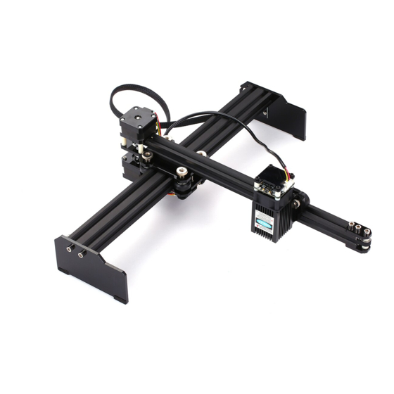
Support:VG-L7
Overall Size:445×401×128mm(L×W×H)
Print Size:330×190mm(L×W)
Powered by VigoTec 2019.s
1. PARTS LIST .................................................................................................................................................................... 1
2. INSTALLATION ............................................................................................................................................................. 1
3. CONTROL-BOARD AND LASER................................................................................................................................ 2
4. NOTICE AND FAQ ........................................................................................................................................................ 3
5. UPDATE .......................................................................................................................................................................... 4
6. WARNING ...................................................................................................................................................................... 4
1. Parts list
Serial N
F1
F2
F3
/
/
/
/
/
/
/
Serial N
N1
N2
N3
2. Installation
Please read the following installation instructions and control board instructions carefully, and pay
CATALOGUE
Parts list of VG-L7 Kits
Parts
Frame Part A (Lower part)
Frame Part B (Upper part)
Laser
Stepper Motor wire
Laser wire
Side to Main control board wire
USB cable
Power supply
Protective glass
Hardware installation manual
VG-L7 Tools
Parts
M5 Nut (Frame Fixed)
M3x12 Screw (Laser Fixed)
M3 Nut (Laser Fixed)
1/4
Quantity
1
1
1
2
1
1
1
1
1
1
Quantity
4
2
2
Advertisement
Table of Contents

Summary of Contents for VigoTec VG-L7
- Page 1 3. CONTROL-BOARD AND LASER..........................2 4. NOTICE AND FAQ ................................ 3 5. UPDATE ..................................4 6. WARNING ..................................4 1. Parts list Parts list of VG-L7 Kits Serial N Parts Quantity Frame Part A (Lower part) Frame Part B (Upper part)
- Page 2 attention to the sequence of installation. The shape of parts in the following installation instructions is only as a sigh. Please refer to the shape of the actual parts purchased. 1. Assemble upper and lower parts. 2. Assemble laser part to the frame. Please notice that the laser wire should penetrate the gap before fix the Laser-Module(F3).
- Page 3 The Motor-X and Motor-Y interface on board should be connected to the X-Part and Y-part motors correspondingly. The 6Pin of the motor wire is for the motor, and the 4Pin is for the control panel. Please connect the laser to the control board with the 3pin wire. Connect the side board to the main control board.
- Page 4 Please contact us if you have any questions. 6. Warning Strictly prohibit laser irradiation of the eyes! Strictly prohibit watching laser without wearing protective glasses! Strictly prohibit using by children! Strictly prohibit using this machine unattended! Powered by VigoTec 2019.
Need help?
Do you have a question about the VG-L7 and is the answer not in the manual?
Questions and answers