
Subscribe to Our Youtube Channel
Related Manuals for Radio-Service E6-32

Summary of Contents for Radio-Service E6-32
- Page 1 "RESEARCH AND PRODUCTION COMPANY "RADIO-SERVICE" JSC INSULATION RESISTANCE TESTER / MEGOHMMETER Е6-32 OPERATION MANUAL...
- Page 2 This Operation Manual is intended for studying of structure and operating principle of the digital Insulation resistance tester / megohmmeter Е6-32 (hereinafter referred to as instrument) and contains the data relevant for proper operation, safety precautions and calibration. Operation conditions of instrument are as follows: - temperature range from 15 to plus 50 ºС...
-
Page 3: Description And Operation
1 DESCRIPTION AND OPERATION 1.1 Designation of instrument Instrument is intended for measurement: - insulation resistance of circuits that are not under voltage; - DC/AC voltage before measurement; - automatically calculate Dielectric Absorption Ratio (DAR) and Polarization Index (PI); - continuity of earth connections and equipotential bonding; - parameters of overvoltage protective devices (varistor voltage of overvoltage suppressors at by direct-current flow 1 mА, static breakdown voltage discharge arresters at DC). - Page 4 Table 1 – Basic metrological characteristics 5 Measurement of spark-gap breakdown voltage at DC Мeasurement range 100 to 3000 V Accuracy (5% + 10 digits) 6 Continuity measurement Мeasurement range 0.01 to 9.99 k Ω Ω Мeasurement range as per IEC 61557-4 0.13 to 10 k Ω...
- Page 5 1.3.11 In case of instrument’s non-use during 2 to 3 minutes it is automatically switched off. 1.3.14 Weight is 0.8 kg max. Overall dimensions are 88х105х245 mm max. 1.3.16 Service life is at least 10 years. 1.4 Completeness Components of megohmmeter delivery set are given in Table 2. Table 2 –...
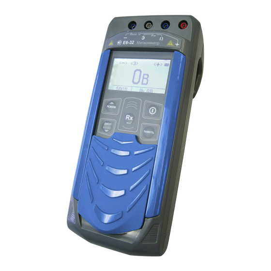
- Page 6 1.5 Design and Operation General view of instrument is given in Figure 1.1. 1 - jack for connection of the power unit (central pin minus – “ ” protective plate (protective cover); – front panel; – handle (hook). – Figure 1.1...
- Page 7 Arrangement of controls and connectors of measuring cables is given in Figure 1.2. 4 – jacks for cables connection; … 5 – LCD display; switches – button megohmmeter on and off; 7 – button calls a memory function (writing, reading, deletion, transmission of measured values to a computer);...
-
Page 8: Intended Use
2 INTENDED USE 2.1 Operation shall be performed by electrotechnical personnel trained and certified for operation in electrical installations and studied this Operation Manual. During operation with the instrument, observe the requirements of "Occupational safety rules during operation of electrical installations" and use the means of protection against electric shock as per "Instruction on use and testing of protection means used in electrical installations". - Page 9 Note. Storage battery is charged at ambient air temperature of plus 10 to plus 30 ºС. Failure to comply with this rule may reduce the storage battery life. To charge the storage battery, connect the output plug of power unit from the delivery set to the instrument jack socket.
- Page 10 Option “GENERAL SETTINGS” allows to changes the contrast level of the display, to select the interface language and to switch on/off the audio warnings. Example of setting is given in Figure 2.1. Figure 2.1 – Menu. Instrument settings Option “SET OF MODES” allows to remove or add to the set of available test types: fixed test voltages (50, 100, 250, 500, 1000 and 2500 V), measurement of continuity (Rcont), measurement of varistor voltage (Uvar), measurement of spark-gap breakdown voltage (Udis), as well as to change the values of user test voltages (Us1, Us2).
- Page 11 Example of user test voltages Us1 and Us2 change is given in Figure 2.2. Figure 2.2 – Menu. Modes Voltages Us1 and Us2 can be also added to the list or removed from it at selection of “Add” or “Delete” options respectively. Option “TEST SETTINGS”...
- Page 12 Figure 2.3 – Memory menu. Recording of result If the measurement is finished more than 20 seconds ago or the instrument is switched off, then to view the last measured value and to record it to the memory of instrument, press button , select "LAST MEASURED RESULT"...
- Page 13 (name lengths is up to ten digits), generating the reports, etc. The program and its detailed description can be downloaded from the company's site www.radio-service.ru. For data exchange with a computer it is required: - turn on PC and run RS-terminal program;...
- Page 14 2.3.5 Insulation resistance measurement Before insulation resistance measurement, the following settings are possible in "TEST SETTINGS" option of the instrument menu: - test duration setting – time of test voltage generation – 1 to 10 minutes; - selection of calculation method for Dielectric Absorption Ratio: D , see item 2.3.6;...
- Page 15 Figure 2.5 – Measurement of cable insulation resistance To avoid the influence of surface leakage currents (e.g. caused by contamination of the measured object surface) use connection diagrams with three measuring cables. In case of insulation resistance measurement between cable wires, the protective ring shall be used (piece of foil mounted on the insulator of one of the wires and connected to the socket "G"...
- Page 16 To view additional information on Dielectric Absorption Ratio (DAR) and Polarization Index (PI) (see item 2.3.6) press button To interrupt measurement before the set time press button Figure 2.7 – Measurement of insulation resistance...
- Page 17 After measurement completion, the residual voltage is removed automatically from the object, its value "Ui" is displayed on the display and accompanied with frequent intermittent audio signal until safe level of 50 V is reached. After measurement completion, the results are shown on the display during 20 seconds and can be recorded to the memory (see item 2.3.2).
- Page 18 Insulation condition is considered to be perfect, if DAR>1.6 (long-term process of the absorption capacity charging by low currents took place), satisfactory - if 1.3 1.6, ≤ ≤ danger - if DAR<1.3 (short-term process of the absorption capacity charging by high currents took place) within the temperature limits from 10 ºС...
- Page 19 2.3.7 Measurement of continuity Use button to select the mode of continuity "Rcont". Connect measuring cables according to Figure 2.8. Figure 2.8 – Measurement of continuity If external noise level at the measurement object allows to perform measurements with the specified accuracy, then display in standby mode shows the symbol .
- Page 20 select option Correct >0<" and press button . After setting to correction menu select “ option “Correct”, close the ends of the measuring cables (short the probes) and press button . The instrument measures resistances of the measuring cables, saves the result in the memory and enables the zero-point correction mode.
- Page 21 Figure 2.10 – Measurement of varistor voltage or spark-gap breakdown voltage Use button to select the mode of varistor voltage Uvar or spark-gap breakdown voltage Udis. To start measurement press button . The measurement results are shown on the display during 20 seconds and can be recorded to the instrument memory (see item 2.3.2).
-
Page 22: Maintenance And Troubleshooting
3 MAINTENANCE AND TROUBLESHOOTING 3.1 General instructions Maintenance includes meeting the rules of operation and storage. Repair of megohmmeter is only allowed at the manufacturer s site or in special repair ’ agencies. 3.2 Possible failures and troubleshooting procedures Possible failures and troubleshooting procedure are provided in Table 3. Table 3 –... -
Page 23: Transportation And Storage
4 TRANSPORTATION AND STORAGE The instrument packed in a standard package allows transportation by all types of transport without any distance limitation. When transported by an aircraft, megohmmeter shall be arranged in a pressurized compartment. Climatic conditions of transportation and storage shall be within the ambient air temperature range from minus 50 to plus 70 ºС... -
Page 24: Acceptance Certificate
6 ACCEPTANCE CERTIFICATE Insulation resistance tester / megohmmeter Е6-32, Reg. No. ________________ complies with the specifications and has been found fit for operation. Head of QCD Stamp here ____________________ _______________________ personal signature print full name __________________ day, month, year 7 DATA ON PRIMARY CALIBRATION Measurement device: Insulation resistance tester / megohmmeter Е6-32, Reg. -
Page 25: Manufacturer's Warranty
Date of sale ________________________________ Seller ________________________________________________________ Seller’s address ________________________________________________ Seller’s phone _________________________________________________ Stamp here Manufacturer’s name and address: Radio-Service, JSC Pushkinskaya street, 268, Izhevsk, Russia. Post code: 426000, P.B. 10047. Phone: +7-3412- 43-91-44. Fax: +7-3412- 43-92-63. E-mail: оffice@radio-service.ru Internet: www.radio-service.ru...
Need help?
Do you have a question about the E6-32 and is the answer not in the manual?
Questions and answers