
Related Manuals for Valloy Incorporation VP-320C

Summary of Contents for Valloy Incorporation VP-320C
- Page 1 User Manual Please read this manual carefully before using the equipment Valloy Incorporation 2018-04 Version Page 1...
- Page 2 © 2018 Valloy Incorporation. This document and the information contained in it is confidential and proprietary property of Vorey Company. Without written consent from Valloy Incorporation, no institution or individual shall transfer or forward it to any third party. © 2018 Valloy Incorporation The content of this document is confidential information of Vorey.
-
Page 3: Table Of Contents
Catalogue Catalogue ……………………………………………………………….…………………………………….…..….2 ………………………………………………………………………………………… Chapter I Safety Precautions …………………………………………………………………… …… Chapter II Transportation and Installation ………………………………………………………………………………… … Chapter III System Introduction 3-1: System parameters…………………………………………………………………………………………….……9 3-2: Components instructions……………………………………………………………………………….….…..….10 …………………………………………………………………… ……………… …… Chapter IV Preparations 4-1: Installation of materials…………………………………………………………………………. .………..……..11 ………………………………………………………………………… Chapter V Operating System Instructions 5-1: Operating instructions of engine panel…………………………………………….……………………….……..13 5-2: Operating instructions of main control system panel……………………………………………………………..14 ……………………………………... -
Page 4: Chapter I Safety Precautions
Chapter I Safety Precautions 1-1 Safety attentions 1. The following are the four basic rules for safety operation which must be followed by operators: (1) Only trained personnel can operate or repair this machine. (2) The operation manual must be read carefully and make sure its content is well understood. (3) Please keep the operation manual near the machine for convenient review. - Page 5 The power shall be tuned off before maintenance or repair. The followingare attentions for maintenance and repair (1) Before maintenance or inspection, please turn off the main power. (2) If power-on maintenance or inspection is necessary, it must be done by authorized electrical technicians.
- Page 6 1-2 Warning labels Before using this product, please read the “safety precaution” to ensure safe use. This product and the recommended consumables has passed test. They can meet strict safety requirements, including safe institution approval and environment standard. Please follow the following instructions to ensure safe use. Warning Product warranty does not cover any unauthorized change, including adding new functions or connecting external device.
- Page 7 1-3 Safety attentions Do not damage or replace the original power cable arbitrarily. The power cable cannot be overbended, pulled, bundled or put under heavy items. These behaviors many cause damage to the power, causing electric shock or fire. If the machine is not in use for a long time, please unplug the power cable from the socket.
-
Page 8: Chapter Ii Transportation And Installation
Chapter II Transportation and Installation 2-1 Case handling Use forklift truck with carrying capacity of more than 1 ton to carry wooden case. 2-2 Packing and unpacking Packing Before packing, fix the four wheels of the machine first and put the machine on mat to prevent sliding. Unpacking Carry out the steps of packing in reverse order. -
Page 9: Chapter Iii System Introduction
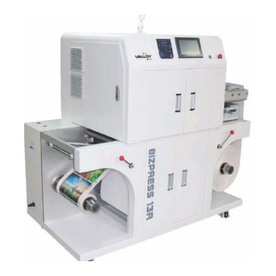
(Other materials are subject to specific test. Untested materials may not be suitable for printing) Application examples Adhesive label, hang tag, food bad and paper box. 3-2: System parameters Machine model VP-320C label printing machine Max. output label paper roll Outer diameter 450MM Label paper width range 140-320MM Max. - Page 10 3-3 VOREY VP-320C digital label printing system components instructions (Exploded view of structural components) Alarm light Main control system panel Engine panel Data port Secondary power Emergency switch Web guide system Pneumatic shaft Unwinding tension Engine front door Air line connector...
-
Page 11: Chapter Iv Preparations
Chapter IV Preparations 4-1: Installation of materials Cooling system Print engine Fuser unit Transfer belt Unwinding Direction Rewinding roller roller Tension system Rewin Feedin Tracking sensor ding g shaft Tension shaft system < PICTURE 4-1 > Please refer to above flow chart for materials installation. Please install materials in the direction of the arrow (see Picture 4-1). - Page 12 < PICTURE 4-3 > < PICTURE 4-2 > < PICTURE 4-4 > < PICTURE 4-5 > < PICTURE 4-6 > Pull the material down the side door and it will return to the rewinding roller till the material is straight. The original installation position must be precise to prevent inclination and the tension shall be adjusted.
-
Page 13: Chapter V Operating System Instructions
Chapter V Operating System Instructions 5-1: Operating instructions of engine panel Engine Control 1. Login 2. Ready for printing 3. Error/fault 4. Main power 6. Save power 8. Printing menu 9. Specification setting 10. Pause printing 12. OK 13. Return 15. Online 16. Information Name Instructions <login>... - Page 14 11 <up><down><left><right> keys Press this key to go to the next menu, item or selection. P.S. When you use <up> and <down> to change current setting, press one key and you can switch quickly among available settings. To display the set default value, please press these two keys at the same time. 12 <OK>...
- Page 15 5-2. Main control system functions Start the machine, make self-inspection and run main program. Click the display area to change values. Name Function Screen display Display status of the machine in various situations (see Item 3 for Status details) Total count Total print length in meter of the machine Last count Last print length in meter...
- Page 16 Configuration Maintenance Pretreatment Tracking sensor Language selection Set the diameter of feeding paper roll core. This function is used to Feeding tension prevent the machine from running without paper. According to the outer Rewinding tension Feeding roll diameter diameter of common inner roll core, the default value is 95 Feeding roll diameter Ready Status: Ready (engine is turned off)
- Page 17 button is not pressed Status: The rewinding air button is not pressed The rewinding tension button is not pressed Status: The tension mechanical button at the rewinding end is not pressed The rewinding tension button is not pressed Paper feeding error Status: EROO1 ( Feeding motor alarm or the feeding tension system has reach a limit Paper feeding error...
-
Page 18: Chapter Vi Software Installation And Instructions
Chapter VI Software Installation and Instructions 6-1: Presetting IP address for the first time To connect with Color DLP VP320C , you need to prepare two static IP addresses in local area network and two network cables, one for the printer and the other for PC. Note: IP address, subnet mask and gateway address are subject to network environment. -
Page 19: 6-2: Installation Of Lpu Software
6-2: Installation of LPU software Operating environment preparation: operating system: Windows7/10 64bit; the whole LUP includes the following software: Adobe Reader XI 11.0.2 gs920w32.exe install.bat FontPack11009_XtdAlf_Lang LPUInstaller (see Picture 6-2, 6-3) 6-2-1 Install Adobe Reader XI 11.0.2. Double click the Adobe Reader XI icon and click "next" according to the wizard till the installation is completed Page 19... - Page 20 6-2-2 Install gs920w32.exe. Double click the Adobe Reader XI icon and click "next" according to the wizard till the installation is completed 6-2-3 install.bat Install . In the PDFColorCounter folder, right click the install icon. Run install.bat as administrator and Page 20...
- Page 21 the system will complete installation automatically 6-2-4 Install FontPack11009_XtdAlf_Lang. Double click FontPack11009_XtdAlf_Lang icon and click "next" according to the wizard till the installation is completed 6-2-5 Page 21...
- Page 22 Install LPUInstaller. Double click LPUInstaller icon and click "next" according to the wizard. 6-2-6 Input the set IP address on the engine control panel. 6-2-7 Page 22...
-
Page 23: 6-3: Setting Of Lpu Software Before Use
Create a new folder in system disk and change the install location to the new created folder. Click "next" according to the wizard. 6-3: Setting of LPU software before use 6-3-1 After installation of AdobeReaderXI, initialization is required before use, and the default open method for printing Actual ⇒... -
Page 24: 6-4: Lpu Software Operating Instructions
6-4: LPU software operating instructions 6-4-1 6-4-2 You can confirm the status of consumables of the You can confirm the status of the printer on the main printer on the main interface. interface. 6-4-3 6-4-4 Basic setting and network setting before the use of the Input the IP address in use in the network setting window printer 6-4-5... - Page 25 6-4-7 6-4-8 In the [material editor], click [add material] and a Click [add material] and a submenu of the [material submenu of the [material editor] will appear. editor] will appear. 6-4-9 6-4-10 After adding a material, you can select the added Input customized information of the material and select corresponding paper thickness and relate it with relevant material on the main menu and input width information...
- Page 26 6-4-11 6-4-12 Click to go to the unit price setting page for You can set the unit price of each consumables needed consumables. to generate cost report in the following page. (Note: See P51 for relevant unit price calculation table) 6-4-13 6-4-14 The default min.
- Page 27 6-4-17 6-4-18 Click "definition auto regulation setting" to enter the The preset value is 210 m, which means the printer will definition auto regulation setting page. regulate definition automatically after printing every 210 meters. Users can also change the setting according to the actual printing effect.
-
Page 28: Chapter Vii Start Printing
Chapter VII Start Printing Before printing, please make sure that the main control panel and the engine panel are ready and each indicator light is green. LPU printing system supports only PDF files For one or several single-page PDF files, select single page After continued printing mode is selected, the setting mode. - Page 29 Click "apply" to apply the information set in Step B, C, D, Click "submit" to submit the file to the printer. E and F. The preview will pop up. If you need to change any set information, click "apply" again. Click cost report and it will appear in a text box.
- Page 30 Pause printing: If you need to pause during printing process, click the "pause" on the main control panel and click "continue" to continue current printing. Note: There is 87 cm blank between each pause and continue. Cancel printing: If you need to cancel current printing, click "cancel" on the engine control panel to cancel current printing.
-
Page 31: Chapter Viii Replacement Of Consumables And Wearing Parts
Chapter VIII Replacement of Consumables and Wearing parts 1: Replace toner cartridge Important • Make sure the power is on when replacing the toner cartridge. • If you need to put the used toner cartridge on the floor or desk, please lay some papers under the toner cartridge to prevent ink spill. - Page 32 8-1-5 8-1-6 Hold the toner cartridge with the arrow up and push it in Close the front cover. slowly till it is fully clipped in. 2: Replace photosensitive drum When the photosensitive drum is near the end of its service life, the engine control panel will show the following information.
- Page 33 8-2-3 8-2-4 Lower the cover, and the photosensitive drum is unlocked. Hold the photosensitive drum handle (R1, R2, R3 or R4) stated in the message and pull the photosensitive drum out gently. 8-2-5 8-2-6 Hole the bottom of the photosensitive drum as is showed in Inset the two prongs on the front of the photosensitive the picture and pull it out of the machine.
-
Page 34: 8-3: Replace Waste Toner Box
8-2-9 8-2-10 Slide the tab till it is fully clipped in. Remove the film Push the photosensitive drum into the shell till it is carefully. completely pushed in. 8-2-11 8-2-12 Turn the unlocking control lever clockwise to lock the Push the cover till it is clipped in. cover. - Page 35 8-3-3 8-3-4 Close the front cover. Hold the left of the waste toner box and push it in till it is clipped in correctly. Note: The waste toner box can be used circularly. You need to remove the tape along the waste toner box and clean the waste powder in it.
-
Page 36: 8-4: Replace Fuser Unit
4: Replace fuser unit When the fuser unit is near the end of its service life, the engine control panel will show the following information. Message Measure Ready for printing Replace fuser The fuser unit shall be replaced immediately. Current capacity can only print about unit ASAP 10,000*1 pages. -
Page 37: 8-5: Replace Ibt Belt Cleaning Component
8-4-5 8-4-6 Hold the fuser unit with one hand and fasten the screws on both Press the middle part of the upper left cover A to close the cover sides with the other hand. gently and then close the side door. 5: Replace IBT belt cleaning component When the IBT belt cleaning component is close to the end of its service lift, the printer's control panel will show the following message. -
Page 38: 8-6: Replace Secondary Transfer Bias Component
8-5-5 8-5-6 Take a new IBT belt cleaning component and inset it into Press the knob to tighten it and fasten the IBT belt cleaning the printer. component in place. 8-5-7 8-5-8 Turn the cover of the IBT belt cleaning component to the Close the front cover. -
Page 39: 8-7: Replace Ibt Component Or Belt
8-6-3 8-6-4 Take the secondary transfer bias component out. Install a new secondary transfer bias component. While installing the secondary transfer bias component, do not touch the roller part. Return the upper left cover A to its original position. Turn on the power. 7: ReplaceIBTcomponent or belt Note: Pull the toner cartridge out before replacing the IBT belt, remove the fuser unit and remove IBT belt cleaning component. - Page 40 8-7-5 8-7-6 1. Remove the screw; 2. Remove the lower left lock 1. Pull the locking locking device out. holder. 8-7-7 8-7-8 Hold the left and right handles and pull the IBT transfer Hold the Front/Rear handles to pull the IBT transfer components to the direction of the arrow component out.
- Page 41 8-7-11 8-7-12 Stand the IBT transfer component upright with the While replace the whole component, take a new one and 1. remove the screws; 2. remove the tension plate. For belt handle facing downward. replacement, skip this step. 8-7-13 8-7-14 When replacing the whole component, 1.
-
Page 42: 8-8: Replace Developer Or Developer Unit
8-7-17 8-7-18 1. Remove the screw; 2. Remove the handle. Remove the driving roller. 8-7-19 8-7-20 Remove the transfer belt. Get a new transfer belt for replacement. Make sure the direction is correct. Install: Install by following the dissemble steps in reverse order. Attentions shall be paid to the following issues. - Page 43 8-8-1 8-8-2 1. Remove screws; 2. open the outer cover of toner 1. Remove the screw; 2. Remove the front and front cover cartridge; 3. remove the outer cover of toner cartridge. together. 8-8-3 8-8-4 1. Disconnect the connector; 2. Remove the screw; 3. 1.
- Page 44 8-8-7 8-8-8 1. Remove the screw; 2. Remove the waste toner assembly. Confirm the port to the waste toner box is closed. Confirm this also during installation. 8-8-9 8-8-10 1. Remove the screw; 2. Remove the wall panel. 1. Pull the connecting piece on the developing room inlet; 2.
- Page 45 8-8-13 8-8-14 Clean the ink powder on the developer. If there is ink When cleaning the inside of the waste powder tube, clean powder on the frame showed in the picture, clean it before the outlet of the waste toner box. Turn the gear showed in installation.
- Page 46 8-8-19 8-8-20 Install triumph plate. Hold the developing box with your hand and pull the new developer into the box. 8-8-21 8-8-22 Turn the gear showed on the picture clockwise to make the The distance between the developer and the installation developer on the magnetic roller distributed uniformly.
- Page 47 8-8-25 8-8-26 Reverse the developer unit to confirm the following issue. Turn the gear clockwise to confirm there is no developer or The Neither the developer or the ink powder shall be on ink powder on the gear as showed in the picture. If there is, the position of DRS Block showed in the picture.
-
Page 48: Chapter Ix Restoration Method After Replacing Wearing Parts
Chapter IX Restoration Method after Replacing Wearing Parts 1: The method to replace fuser unit After replacing the fuser unit, please perform corresponding control panel operations to reset each counter. When you are replacing the fuser unit, please make sure that you reset the counter on the control panel. Consumables menu 1. - Page 49 2: The method to replace IBT transfer cleaning component Consumables menu 1. On control panel, press <down> and <OK> keys at the Machine No. same time, and it will show [consumables menu]. Consumables menu Reset counter 2. Press <down> till it shows [rest counter]. Reset counter Fuser unit 3.
-
Page 50: 9-3: The Method To Replace Secondary Transfer Bias Component
3: The method to replace secondary transfer bias component Consumables menu 1. On control panel, press <down> and <OK> keys at the Machine No. same time, and it will show [consumables menu]. Consumables menu Reset counter 2. Press <down> till it shows [rest counter]. Reset counter Fuser unit 3. -
Page 51: 9-4: The Method To Print Hfsi Counter Report
4: The method to print HFSI counter report 1. On the engine control panel, press <up> three times and then press <specification setting>. Then it will show [printing language setting]. 2. Press <down> till it shows [report/list]. 3. Press <right> or <OK> to select and show [operation record report]. 4. -
Page 52: 9-6: The Method To Input Atc Value When Replacing The Developer Unit
5. Restoration method of transfer belt In diagnosis mode: press <left+right> on the engine control panel and release them at the same time, and then press <online> key. 1. It will show [preventive diag]. 2. Press <right> to display [DC122 Sd History]. 3. -
Page 53: Chapter X Other Settings And Instructions
Chapter X Other Settings and Instructions 1:Instructions on material setting For better printing effect of different materials, temperature and transfer voltage shall be regulated as follows: LPU setting Corresponding temperature Corresponding voltage Ultra-low temperature 1 Common paper Ultra-low temperature 2 Thick paper 1 Ultra-low temperature 3 Thick paper 2... -
Page 54: 10-2: Adjustment Of Chroma
After setting, press <specification setting> to return to the <ready for printing> page. 2: Adjustment of chroma If the color breaks, you can use color level correction to adjust chroma. Color level correction can make your printing quality consistent. To make color level correction, please print color level correction table of the printer and compare this table with the printer's accompanying "color sample for color level correction"... - Page 55 determine its chroma value (e.g. [text]). 8. Press <left> or <OK> to select and it will show [color level correction table]. 9. Press <down> to show <adjust setting>. 10. Press <left> or <OK> to select and show <cyan (C)]. Here we will calculate the chroma of cyan. No content shall be changed in the following steps.
- Page 56 3: The setting of consumables unit price (example) Price per page Note Name Life Price Price divided by Black ink 26000 pages 2600 service life equals price per paper. Input Color ink 18500 pages 1850 the price of each paper to the unit price Black cartridge 70000 pages 7000...
-
Page 57: 10-4: The Setting Of Secondary Printer Sensor
4: The setting of secondary printer sensor Simple setting The light source is on the detected color and press ON button to finish the setting, which is very simple. Working status indicator light ON button OFF button 1. Put the light source on the color symbol and press ON 2. -
Page 58: Chapter Xi Daily Maintenance And Cleaning
Chapter XI Daily Maintenance and Cleaning To make sure this product has reliable operation and high quality prints, users shall do necessary regular inspection and maintenance steps, including mechanical structure inspection, occasional cleaning and consumable replacement. To maintain the printing transmission is in a good working condition, all-around and regular maintenance is very necessary. -
Page 59: 11-1: Cleaning Of Print Head
1. Cleaning of the print head 11-1-1 11-1-2 Confirm the printer is not in running and open the front cover. Turn the unlocking control lever on the cover of the photosensitive drum anticlockwise. 11-1-3 11-1-4 Take the cleaning stick sealed in the LED print head Lower the cover. -
Page 60: 11-2: Cleaning Toner Cartridge
2: Cleaning toner cartridge 11-2-1 11-2-2 Put the toner cartridge taken out flat on a table and do not touch the surface of the core with your hand. Turn the toner cartridge as is indicated by the arrow till the dust-free cloth with ethyl alcohol wipe the dirty spots off.Do not leave residual ethyl alcohol on the surface. -
Page 61: Chapter Xii Troubleshooting
Chapter XII Troubleshooting 1. Poor image quality Phenomenon Reason Solution Dirty spot on the LED print head 1. Cleaning LED print head, LED print head damage 2. Replacing cleaning stick. 3. Replace LED print head Note: For C/M/Y/K, handle the color with white line only. - Page 62 Red roller of fuser 94.8mm Black roller of fuser 87.92mm It may happen when using paper easy to 1. Remove the transfer cleaning have scraps component to confirm if there is any Transfer cleaning component foreign matter on the front of the scrapper.
-
Page 63: Warranty
Chapter XII Equipment warranty “ ” Ningbo Valloy Incorporation Co., Ltd. ( Vorey hereunder) will provide reasonable monitor and preventive measures to make sure that users can use qualified products. Under any circumstances, Vorey's responsibilities are limited to the contract price and it will not be responsible for the other parts beyond the contract price.
Need help?
Do you have a question about the VP-320C and is the answer not in the manual?
Questions and answers