Table of Contents
Advertisement
Quick Links
Advertisement
Table of Contents

Summary of Contents for Advanced Radio Smart Bus
- Page 1 Smart Bus Quick Start Guide...
- Page 2 Thank you for your purchase of the Advance Radio Smart Bus. In this quick start guide we will show you how to connect your new Smart Bus, General use and Set Up. Please take the time to understand this guide before...
-
Page 3: Included Items
Independent servo reverse on 5 channels and all 6 adjustable outputs. • 3 point matching on 5 channels and all 6 adjustable outputs. • 15 point matching on 5 channels and 6 adjustable outputs (Smart Bus Extreme only) • Digitally selectable regulator output via the Smart Screen. •... -
Page 4: Installation And Mounting Instructions
The Smart Bus Extreme and Smart Bus Plus have a built in digital regulator that uses the base plate as a heat sink. It is important that the Smart Bus should be mounted so aire can flow over the base plate to allow effective heat dissipation. We recommend mounting with minimum standoff spacers of 1/2 inch or 12mm to allow adequate air flow over the base plate. - Page 5 Mounting the Smart Display There are 2 options of mounting the Smart display. NOTE: Which ever method of mounting you choose, ensure the cable that comes out of the Smart Display is not crushed in anyway. Doing so will reduce the longevity of the ca- bles.
-
Page 6: Installing The Receiver
Locate the channels on your receiver and plug in the corresponding JR connectors from the header, these cables can be extended using extension leads if needed. Repeat this for all channels needed. Step 2 Now install the pin header into the Smart Bus. Ensure the header is pushed snug into the Smart Bus Input port. - Page 7 Optional Ignition Module If you purchased the Smart Bus optional ignition module then you will be able to easily control the igni- tion system in your model via the Smart Bus. This ignition module is a high quality optically isolated design that minimises ignition noise and provides regulated 6 volts supply at up to 3A to power your gas engines’...
- Page 8 To switch the Smart Bus ON or OFF do the following: Press button “A” and within 2 seconds press button “B”. If the Smart Bus is in the ON position it will turn OFF. If the Smart Bus is in the OFF position it will turn on.
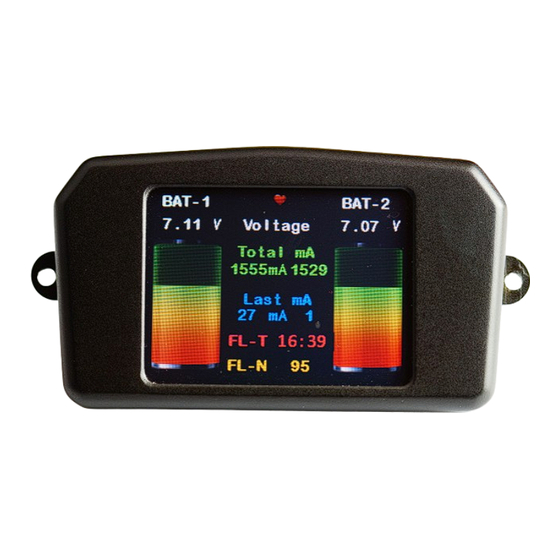
- Page 9 General Usage and Screen Information Important: The Smart Display that is supplied with the Smart Bus is a touch screen display. It is used in both setup and provides feedback to the user about battery voltage and milliamps used. The screen is designed to be mounted in a model for quick and easy use. However the Smart Bus will operate win normal flying mode without the Smart Screen connected.
- Page 10 Please make sure your battery packs are fully charged before making the servo output volt- age selection. The Smart Bus will read the battery voltage and will make available only the voltages that will work for your selected battery type. All other choices will be greyed out and are not selectable.
- Page 11 Reset Resets sub trim values to default. Multi Takes you to the Multi-point match page (only available on Smart Bus Extreme). Vertical Bars Shows the current sub trim amount at the center and endpoints for that servo. These values are changed by the INC,...
- Page 12 15 Point Servo Matching Return Takes you back to the previous screen. Reset Resets the sub trim values back to default. Vertical Bars Shows the sub trim applied to the servo. The sub trim values can be changed using the DEC, buttons.
- Page 13 First Time Battery Setup We are now going to go proceed with a first time setup of the Smart Bus . Please ensure your batteries are fully charged before you setup the Smart Bus. If you need any addi- tional help with what each button or item does please read the General Usage and Screen information page located on page 7 of this manual.
- Page 14 Note: Step 4 is extremely important, Please en- sure the capacity is set correctly to the battery packs you are using. The Smart Bus uses this capacity value to show the remaining battery capacity on the main screen. If you set this value incorrectly then the remaining capacity indicators may not show the correct remaining battery capacity.
- Page 15 During this stage, we will install the receiver and servos. Note: Before plugging any ser- vos into the Smart Bus, ensure you have set the regulator to the desired voltage range. Important: Check the recommended voltage range of your servos, supplying to high of a voltage to your servos may cause them damage.
- Page 16 Step 3 The buttons on the screen match up with the first 5 channels on the Smart Bus. Press the button for the channel you wish to work on. Step 4 You should now see the 3-point matching screen. At the bottom of the screen you will see the name of the servo channel you are sub trimming for example “AIL1-B”.
- Page 17 15 Point Matching (Smart Bus All Versions) 15 point matching is useful for getting the best possible match between servos. This in- cludes mechanically matched servos (aileron) or non mechanically matched (left and right elevator). We are now going to go through the 15 point servo matching process. For best results please do 3 point match before proceeding.
-
Page 18: Factory Reset
Smart Bus back to the original factory settings. Switching the Smart Bus to a different model for example would be one of the situations. When you select the Factory Reset feature all the sub-trim data and battery settings will be erased and the Smart Bus will be returned to “Out- Of-The-Box” settings. -
Page 19: Screen Calibration
Screen Calibration The Smart Display is a touch screen display. It has been pre-calibrated at the factory and very rarely will need calibration. If the screen button become miss-aligned due to changes in oper- ating conditions it may be necessary to recalibrate the touch screen. Screen calibration is ONLY used to realign the touch screen with the display. -
Page 20: Additional Screens
Additional Screens Cockpit Simulation Screens The Smart Bus also comes with additional simulation screens that simulate a real cockpit. These include an artificial hori- zon and instrumentation. To view these new screens touch the bottom center of the smart screen page. An example can be seen to the right. - Page 21 If I change the batteries in my model or move the Smart Bus to a different model will I have to setup the switch again? Yes, The switch relies on the information that you program into it to be accurate.
- Page 22 Notes...
- Page 23 Notes...
-
Page 24: Contact Information
Loss of time, inconvenience, loss of model, or other incidental or consequential damages. Contact Information Booma RC Advanced Radio support : support@boomarc.com For more sales information contact us at: sales@boomarc.com sales1@boomarc.com...
Need help?
Do you have a question about the Smart Bus and is the answer not in the manual?
Questions and answers