Table of Contents
Advertisement
Quick Links
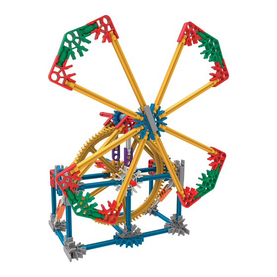
Experiment #1
Using a Spur Gear
System in a Crank Fan
Objectives: Understand and describe the transfer of
motion through a spur gear system and investigate the
relationship between gear size, speed of rotation and force.
Materials You Will Need:
built CRANK FAN model
masking tape
paper or notebook
PROCESS:
1. Build the CRANK FAN model by following the step-by-step building instructions.
2. Explore your model. Locate and identify the gears. Watch the gear mechanism in
operation as you turn the crank.
3. Using your notebook, explain how the gear system turns the fan blades. How do
the fan's gears fit together? Are they in line with each other?
79318
1
®
Education
Advertisement
Table of Contents

Related Manuals for K'Nex Education 79318


Summary of Contents for K'Nex Education 79318
- Page 1 Experiment #1 79318 Using a Spur Gear System in a Crank Fan Objectives: Understand and describe the transfer of motion through a spur gear system and investigate the relationship between gear size, speed of rotation and force. Materials You Will Need: built CRANK FAN model masking tape paper or notebook...
- Page 2 4. This arrangement is called a Spur Gear System. In this arrangement, the gears fit together, or mesh, along the same line or in the same plane. In the Crank Fan, the gears are arranged one above the other. Turn your model on its side so you can see how the gears are in line with each other.
- Page 3 7. Attach a small piece of masking tape to the edge of one fan blade and select a reference point so you can keep track of the fan blade as it rotates. (a) Turn the crank to make one rotation. Continue turning the crank but vary the speed at which it is turned.
- Page 4 (b) Discover if your predictions were correct by rebuilding your models with two gears that are different in size using these images. (c) Think of a way to compare the speed that the fan turns, with the speed of the crank when the big gear is attached to the crank and the small gear is attached to the fan blades.
- Page 5 EXTENSION ACTIVITY: Gear Ratios 1. You used a crude measurement to compare the input and output speeds of the gear wheels in the experiment you just performed. What you discovered was a simple Gear Ratio. 2. A more accurate approach is to compare results by counting the number of teeth on each gear wheel.
- Page 6 (d) Determine the gear ratio of your crank fan. Write down the gear ratio in your notebook and describe, in your own words, what the gear ratio means in reference to their crank fan. (e) What is gained by using this gear train? Did your fan turn quickly or slowly? 5.
Need help?
Do you have a question about the Education 79318 and is the answer not in the manual?
Questions and answers