Table of Contents
Advertisement
Quick Links
Application Notes
1 Scope
These application notes are a guide to applying the
G123-817-006 LVDT Oscillator Demodulator. The following is a
summary of the process that these application notes apply to:
• Select the LVDT you will use.
• Determine the required oscillator level and frequency.
• Wire a test unit for performance checking.
• O ptimise performance on the test unit by adjusting oscillator
level, oscillator frequency, phase, output span and output
zero.
• Apply your design.
The G123-817-006 is not a "plug and play" device. It needs to
be carefully optimised for the particular LVDT being used.
LVDT selection criteria and closed loop considerations are not
covered by these application notes.
2 Description
The G123-817-006 is a general purpose LVDT oscillator
demodulator that can be configured to suit a wide variety of
series opposed (4 wire) LVDTs. To produce optimum results,
a knowledge of the characteristics of the LVDT being used is
required.
For a more detailed description refer also to data sheet
G123-817.
The G123-817-006 is an improved version of the
G123-817-002. It does not have a 3.5/8.0V oscillator selector
switch and has improved common mode noise rejection.
3 Installation
3.1 Placement
A horizontal DIN rail, mounted on the vertical rear surface of
an industrial steel enclosure, is the intended method of
mounting. The rail release clip of the G123-817-006 should
face down, so the front panel and terminal identifications are
readable and so the internal electronics receive a cooling
airflow. An important consideration for the placement of the
module is electro magnetic interference (EMI) from other
equipment in the enclosure. For instance, VF and AC servo
drives can produce high levels of EMI. Always check the
EMC compliance of other equipment before placing the
G123-817-006 close by.
3.2 Cooling
Vents in the top and bottom sides of the G123-817-006 case
provide cooling for the electronics inside. These vents should
be left clear. It is important to ensure that equipment below
does not produce hot exhaust air that heats up the
G123-817-006.
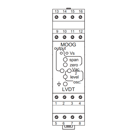
LVDT Oscillator Demodulator
Top vents
13
9
output
1
5
Bottom
vents
3.3 Wiring
The use of crimp "boot lace ferrules" is recommended for the
screw terminals. Allow sufficient cable length so the circuit
card can be withdrawn from its case with the wires still
connected. This enables switch changes and pot adjustments
on the circuit card to be made while the card is still connected
and operating. An extra 100mm for cables going outside the
enclosure, as well as for wires connecting to adjacent DIN rail
units, is adequate. The LVDT cable should be 3 twisted pairs
with an overall screen.
Enclosure
Grounded EMI
cable gland
Cable
Radial screen
termination
Preferred wiring
G123-817-006
Cover
release
tab (2)
Screw
terminals
9 - 16
14
15
16
10
11
12
DIN rail
MOOG
Vs
span
zero
Vac
2
level
osc.
LVDT
2
3
4
Screw
6
7
8
terminals
1 - 8
DIN rail
release
clip
Cooling
airflow
Wires
100mm Loop
Page 1 of 4: C70880 Rev E – 11.15
Advertisement
Table of Contents

Related Manuals for Moog G123-817-006

Summary of Contents for Moog G123-817-006
- Page 1 3 Installation on the circuit card to be made while the card is still connected and operating. An extra 100mm for cables going outside the 3.1 Placement enclosure, as well as for wires connecting to adjacent DIN rail units, is adequate. The LVDT cable should be 3 twisted pairs A horizontal DIN rail, mounted on the vertical rear surface of with an overall screen. an industrial steel enclosure, is the intended method of mounting. The rail release clip of the G123-817-006 should Enclosure Wires face down, so the front panel and terminal identifications are readable and so the internal electronics receive a cooling Grounded EMI airflow. An important consideration for the placement of the cable gland module is electro magnetic interference (EMI) from other 100mm Loop equipment in the enclosure. For instance, VF and AC servo drives can produce high levels of EMI. Always check the EMC compliance of other equipment before placing the G123-817-006 close by.
- Page 2 Vac and circuit card TP2. Set an oscillator level The accepted method is to radially terminate the cable screens, in an appropriate grounded cable gland, at the point of entry with the front panel level pot so that the signals are free of into the industrial steel enclosure. If this is not possible, chassis noise and ripple, so a clear, easily read signal is displayed. ground screw terminals are provided on the G123-817-006. Ensure that the level is not so high as to distort the waveform. Exposed wires should be kept to a minimum length. Connect Select other frequencies with the frequency select switches to the screens at both ends of the cable to chassis ground. see if a minimum phase difference can be achieved. Select the frequency that gives a minimum phase difference. Be aware 4 Power supply that there is an adjustment on the circuit card that reduces the ...
- Page 3 5.3 Secondary phase difference the oscillator is not over loaded. Set to 20mA if using the 4-20mA signal output. The G123-817-006 circuit uses the primary signal to synchronously detect the secondary signal. Phase differences 6 Withdrawing the circuit card between these signals can cause minor errors and so there is the facility on the circuit card to null phase differences. from its case Withdraw the circuit card from its case and connect a dual ...
-
Page 4: Specifications
AS4251.1 emission Signal 0V Front panel Output span trimpots: Output zero Internet Data Oscillator level For a detailed Data Sheet and the latest version of this Full scale sensitivity: Min: 0.15 V/ V Application Note please refer to the Moog website Max: 0.9 V/ V www.moog.com/dinmodules Industrial Controls Division. Moog Inc., East Aurora, NY 14052-0018. Telephone: 716/687-4954. Fax: 716/655-1803. Toll Free 1-800-272-MOOG. Moog GmbH. Germany. Telephone: 07031-622-0. Fax: 07031-622-100. Moog Sarl. France. Telephone: 01 45 60 70 00. Fax: 01 45 60 70 01. Moog Australia Pty. Ltd. Telephone: 03 9561 6044. Fax: 03 9562 0246. Moog pursues a policy of continuous development and reserves the right to alter designs and specifications without prior notice. Information contained herein is for guidance only and does not form part of a contract. Australia: Melbourne, Sydney, Brisbane Austria: Vienna Brazil: S ao Paulo Denmark: Birkerød England: Tewkesbury Finland: Espoo France: Rungis Germany: Böblingen, Dusseldorf ...
Need help?
Do you have a question about the G123-817-006 and is the answer not in the manual?
Questions and answers