Advertisement
Installation, Operation &
Maintenance Instructions
This manual is for the guidance of operators of the above Carbolite products
and should be read before the furnace is connected to the electricity supply.
Section
1.0
2.0
3.0
4.0
5.0
6.0
7.0
8.0
9.0
Manuals are supplied separately for the furnace controller
Please read the controller manuals before operating the furnace.
1.0
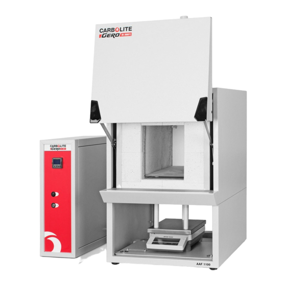
1000°C - 1100°C Furnaces
types AAF, OAF, GSM & VMF
C
ONTENTS
(and overtemperature controller when fitted).
page
2
3
4
7
8
14
15
18
19
MF06
Advertisement
Table of Contents

Summary of Contents for Keison CARBOLITE AAF Series
-
Page 1: Table Of Contents
Installation, Operation & Maintenance Instructions 1000°C - 1100°C Furnaces types AAF, OAF, GSM & VMF This manual is for the guidance of operators of the above Carbolite products and should be read before the furnace is connected to the electricity supply. ONTENTS Section page... -
Page 2: Descriptions
AAF, OAF, GSM, VMF ESCRIPTIONS The chamber furnaces covered by this manual all have some specialist feature as follows. AAF models The AAF Ashing Furnaces incorporate pre-heated chamber air flow. The chambers of the AAF 11/3 and AAF 11/7 are ceramic muffles wound with resistance wire. The model AAF 11/18 has a chamber heated by wire spirals mounted in ceramic carriers, isolated from the working chamber by side walls of silicon carbide. -
Page 3: Installation
AAF, OAF, GSM, VMF NSTALLATION Unpacking & Handling When unpacking or moving the furnace always lift it by its base. Never lift it by the door. Use two people to carry the furnace where possible. Remove any packing material from the door gear and furnace chamber before use. -
Page 4: Operation
AAF, OAF, GSM, VMF Green/Yellow to earth (ground) “Universal Wiring” Year 2000: 18 litre 3-phase models only Year 2001: 18 litre 1-phase and 3-phase The model AAF 11/18 can be easily rewired between 1-phase and 3-phase supplies. This applies to 3-phase+N and 3-phase delta in the ranges 380/220V–415/240V and 208-240V, but does not apply to 3-phase star without neutral (e.g 380V). - Page 5 AAF, OAF, GSM, VMF MF06...
- Page 6 AAF, OAF, GSM, VMF General Operating Advice Heating element life is shortened by use at temperatures close to maximum. Do not leave the furnace at high temperature when not required. The maximum temperature is shown on the furnace rating label and on the back page of this manual. When heating large objects, in particular poor conductors, avoid shielding the thermocouple from the heating elements.
-
Page 7: Maintenance
AAF, OAF, GSM, VMF AINTENANCE General Maintenance No routine maintenance is required other than removal of soot deposits mentioned in 3.3 and the occasional replacement of consumable items. The furnace outer surface may be cleaned with a damp cloth. Do not allow water to enter the interior of the case or chamber. -
Page 8: Repairs & Replacements
AAF, OAF, GSM, VMF & R EPAIRS EPLACEMENTS Safety Warning – Disconnection from Supply Always ensure that the furnace is disconnected from the supply before repair work is carried out. Safety Note - Refractory Fibrous Insulation This furnace contains refractory fibres in its thermal insulation. These materials may be in the form of fibre blanket or felt, vacuum formed board or shapes, mineral wool slab or loose fill fibre. - Page 9 AAF, OAF, GSM, VMF MF06...
- Page 10 AAF, OAF, GSM, VMF Thermocouple Replacement Disconnect the furnace from the supply, and remove the furnace back panel. Make a note of the thermocouple connections. The negative leg of the thermocouple is marked blue. Compensating cable colour codings are: Negative positive (type K) White green...
- Page 11 AAF, OAF, GSM, VMF Replace the thermocouple and sheath and remake the electrical connections. In porcelain and brass terminal blocks the brass connector should be slightly loose in its porcelain support block to allow for expansion. Replace the back panel and reconnect the electrical supply. Switch the furnace ON and heat to 900°C without interruption, and then soak for 1 hour.
- Page 12 AAF, OAF, GSM, VMF Slab Element Replacement (OAF 11/2) See section 5.2 - wearing a face mask is recommended. The twin chamber contains two slab elements which form the heated floors of the upper and lower sections. The elements are made of refractory cement in which coiled heating wire s embedded. Disconnect the furnace from the electrical supply.
- Page 13 AAF, OAF, GSM, VMF Door Plug Replacement Lift the furnace door to the open position and remove the door cover from the plug carrier assembly. Remove the old door plug by sliding it upwards out of its carrier. Slide the new plug into the carrier assembly making sure that the plug is the correct way up. Refit the door cover.
-
Page 14: Fault Analysis
AAF, OAF, GSM, VMF AULT NALYSIS A. Furnace Does Not Heat Up The HEAT light The heating Check also that the SSR is working is ON element has failed correctly The HEAT light The controller The thermocouple has broken or has a is OFF shows a very high wiring fault... -
Page 15: Circuit Diagrams
AAF, OAF, GSM, VMF IRCUIT IAGRAMS Safety switches type A: two Door Switches in the element circuit in models up to 25A rating. Safety Switch type B: a single Door Switch in the contactor coiled circuit in models over 25A. AAF, VMF, GSM or OAF 11/1 single phase for AAF 11/18 see diagram 7.4... - Page 16 AAF, OAF, GSM, VMF MF06...
- Page 17 AAF, OAF, GSM, VMF Applies only to AAF 11/18 3-phase “universal” wiring Filters (if fitted) Contactors Supply light & (2 or 3) Instrument Switch heat heat heat coil coil safety switch if fitted overtemp. controller thermocouple temperature controller thermocouple Fuses F1 are always present in this wiring design. Fuses F2 could be absent in some circumstances, if the circuit does not exceed 10A.
-
Page 18: Fuses & Power Settings
AAF, OAF, GSM, VMF 2-phase models The OAF models can be made for use on 2 phases of a 3-phase plus neutral supply. If a diagram is required please contact Carbolite. 8.0 F & P USES OWER ETTINGS Fuses F1-F3: Refer to the circuit diagrams. Internal Fitted if supply cable fitted. -
Page 19: Specifications
Tel: +44 (0)1245 600 560 Tel: +41 41 541 5877 Fax: +44 (0)1245 600 030 Fax: +41 41 541 5878 Email: Email: General Information/Sales: General Information/Sales: info@keison.com info@kesn.ch Accounts Department: Accounts Department: accounts@keison.com accounts@kesn.ch USA Office Latin America Office 233 Rogue River Highway #425...