Table of Contents
Advertisement
Advertisement
Table of Contents

Summary of Contents for Polargos EASY WAY202
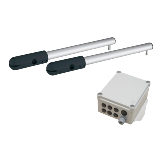
- Page 1 AUTOMATIC GATE EASY WAY202 Assembly and service manual...
- Page 2 100 x 100 mm, 8 sets of carriage bolts M8 x 120 mm will be required. Depending on a model purchased, the suitable connector should be included in the set EN - Assembly and service manual for EASY WAY202...
-
Page 3: Table Of Contents
Electric box fastening on the post Troubleshooting Antenna connection Technical assistance Remote control battery replacement Drive connection Cancellation of settings Connection of two actuators Drive locking / unlocking Diagnostics Connection to the mains EN - Assembly and service manual for EASY WAY202... -
Page 4: Introduction
Introduction POLARGOS is a Polish company manufacturing property and industrial fences as well as another steel products that has been present at the market since 1994. Thanks to our many years’ experience, technical and marketing background, POLARGOS manufactures products that are appreciated by more and more customers at home and abroad. -
Page 5: Safety Rules
The user is obliged to transfer all worn out electronic and electric devices to a special waste collection point for recycling. Hereby, POLARGOS declares that this product conforms to the basic requirements and another relevant regulations of the Directive 1999/5/CE. The Declaration of Conformity is available at www.polargos.pl The product admitted for use in European Union and Switzerland. -
Page 6: Important
▶ Regulatory compliance Hereby, POLARGOS declares that the product described in this manual, if it is used according to the given recommendations, conforms to the basic requirements of European Directives in force and, in particular, the Machinery Directive 2006/42/EC and Radio Equipment Directive 2014/53/EU. -
Page 7: Dangerous Zone Determination
12 cm or at most 5 mm between the lower part 5 mm 12 cm 12 cm 5 mm of the leaves and the substrate. 12 cm 5 mm min. min. max. min. max. EN - Assembly and service manual for EASY WAY202... -
Page 8: Product Presentation
• Spare battery input Yes (only at 230V) • Photocell input • Control input of dry contact type • Buil-in antenna * Opening time can be different, depending on the gate parameters. EN - Assembly and service manual for EASY WAY202... -
Page 9: Leaf Dimensions And Maximum Weight
▶ Opening stop (not included in the delivery) The motor stops automatically at its internal limiter. To stop the gate earlier, set a stop (not delivered) on the substrate to stop the leaves. EN - Assembly and service manual for EASY WAY202... -
Page 10: Preparation For Assembly
Set stops at the desired opening angle of the gate. The angle should be within the range of 85-95°. The opening angle of the both leaves should be the same: α=α’. The opening stop is not included in the delivery. EN - Assembly and service manual for EASY WAY202... -
Page 11: Necessary Tools
13 flat screwdriver open ended spanner 17 10,5 hammer drill skinning pliers pincers tubular spanner 13 i 10 distribution box clamp EN - Assembly and service manual for EASY WAY202... -
Page 12: Preliminary Wiring System
3 mm between contacts, at each pole (according to EN 60335-1). It is recommended to install a lightning arrester (maximum residual voltage of 2 kV). EN - Assembly and service manual for EASY WAY202... -
Page 13: Preparation Of Connectors
M8 x 120 mm. NOTE: View from the estate side! POST 100x100 POST 100x100 8 SETS NOTE: Top view! LEFT POST RIGHT POST 100x100 mm 100x100 mm LEFT FASTENER RIGHT FASTENER EN - Assembly and service manual for EASY WAY202... - Page 14 IMIĘ I NAZWISKO PODPIS DATA NARYS. SPRAWDZ. ZATWIER. WYPROD. zawias MATERIAŁ: Z.JAKOŚCI WAGA: VARIANT IIIB. – ASSEMBLY WITH A CAVITY 8 SETS depending depending on the post on the post dimension dimension EN - Assembly and service manual for EASY WAY202...
-
Page 15: Automatic System Assembly
Automatic system assembly Gate preparation Level the gate leaves. View from the estate side Fix the automatic system position. Outermost mandrel Apply the prepared set to the closed gate levelled before. The automatic system must not scrape the fastening to the gate. View from the estate side POST 100x100... - Page 16 The fastening to the gate should be adjustable using fine displacements (tighten the screws to feel only weak resistance). Then, when the gate is closed, install the fastener to the post. EN - Assembly and service manual for EASY WAY202...
- Page 17 Then, drill it from the street side using a drill Then install a carriage bolt M6 x 40 mm. choose one hole (of three) that does not overlap the pale and drill the gate crosspiece. EN - Assembly and service manual for EASY WAY202...
- Page 18 Do not mount the screw underneath. Fasten the yoke that fastens the leaf on the drive mandrel. Attach the unlocking element to the drive mandrel to lock the mandrel. For the other gate leaf, repeat steps EN - Assembly and service manual for EASY WAY202...
-
Page 19: Electric Connection
• Connection to the mains or to the solar system.. ▶ Electric box location on the post. Install the box at the power supply source side. View from the estate side EN - Assembly and service manual for EASY WAY202... -
Page 20: Control Module Assembly
Press slightly to locate elements properly. Fasten the equipment using the clamping screw (included). Mount the box with the gland downward. Conductors will be led in the lower part (as shown in the picture). EN - Assembly and service manual for EASY WAY202... -
Page 21: Antenna Connection
Control module assembly AUTO ON/OFF ▶ Antenna connection To ensure optimum operation, it is recommended to lead the antenna conductor from the box through a bush. Never cut the antenna conductor. EN - Assembly and service manual for EASY WAY202... -
Page 22: Drive Connection
M1 actuator activates the right leaf that opens first and closes as last. Connect the drives as shown in the following table: Connect conductor of drive To terminal blue brown blue brown EN - Assembly and service manual for EASY WAY202... -
Page 23: Connection To The Mains
The ground conductor (green/yellow) will be necessary for some accessories (lighting 230 V class I). Connect the phase and the neutral point. Check if the conductors are locked properly while pulling them. EN - Assembly and service manual for EASY WAY202... - Page 24 It is necessary to follow recommendations concerning colours of the conductors. Blue conductor Neutral PROG See Fig. No. 1, above Red/brown/black conductor Phase AUTO Green/yellow conductor Grounding ON/OFF Clamp the gland. Check if the conductor is locked properly while pulling it. EN - Assembly and service manual for EASY WAY202...
-
Page 25: Start-Up And Standard Use
Opening of the one leaf only by short pressing of the remote control button to allow pedestrian passage. Complete opening of two leaves by a longer pressing of the remote control button. EN - Assembly and service manual for EASY WAY202... -
Page 26: Switching On The System Power Supply
WARNING Once the installation is complete, it is necessary to check if the obstacle detection system conforms to the specification given in the Annex A of EN 12 453. EN - Assembly and service manual for EASY WAY202... -
Page 27: Setting The Stand-By / Activation Mode Of The Electronic Control System
▶ Training for users All users must know the rules of fully safe use of this gate with electric drive (the standard use and the method of unlocking) and of mandatory periodical surveys. EN - Assembly and service manual for EASY WAY202... -
Page 28: Advanced Settings
The lamp lights up and then goes out. The mode of opening to allow pedestrian passage has been activated in this button. EN - Assembly and service manual for EASY WAY202... -
Page 29: Automatic Closing
Release the button 2, the lamp flashes; the lamp goes out and then it lights constantly. press the button 1 of the remote control twice. The lamp keeps lighting. The automatic closing function is ON. EN - Assembly and service manual for EASY WAY202... -
Page 30: Switching Off The Automatic Closing
Press the button 2 of the remote control. Press the button The lamp The lamp flashes. 1 of the remote is OFF. control twice. The automatic closing function is OFF. EN - Assembly and service manual for EASY WAY202... -
Page 31: Remote Control Programming
Somfy RTS pedestrian passage or another automatic mechanism of Somfy RTS Method 4 Another equipment Inny mechanizm Inny mechanizm Complete opening of Somfy RTS automatyczny Somfy RTS automatyczny Somfy RTS EN - Assembly and service manual for EASY WAY202... -
Page 32: Addition Of A Remote Control
The lamp lights up. The remote control has been saved in the memory. Cancellation of remote controls – see page 37-38 EN - Assembly and service manual for EASY WAY202... -
Page 33: Accessory Wiring
Before connection of photocells, remove the conductor (jumper) from between terminals 3 and 4 of the electronic module. EN - Assembly and service manual for EASY WAY202... -
Page 34: Orange Light
10 W - 24 W can result in improper operation of the drive unit.. ▶ Orange light operation The orange light flashes when the gate is moving. EN - Assembly and service manual for EASY WAY202... -
Page 35: Battery
The antenna is connected to terminals 1 and 2 (blue label „ANT”) of the control module: the conductor core to terminal 1; the stranded aerial wire to terminal 2. EN - Assembly and service manual for EASY WAY202... -
Page 36: Video Interphone
(the wire control is inactive), • the wire protecting accessories (photocells, the orange light) are still active. EN - Assembly and service manual for EASY WAY202... -
Page 37: Troubleshooting
1 of the remote of the electronic on the disc. control until the lamp control once. control system for 2 s. The lamp „RESET” starts flashing. The lamp lights up. flashes. EN - Assembly and service manual for EASY WAY202... -
Page 38: Drive Locking / Unlocking
Locking the drives Unfasten the unlocking element and then remove the Install the actuator. Fasten the unlocking element on the actuator from the leaf holder. drive mandrel to lock the mandrel. EN - Assembly and service manual for EASY WAY202... -
Page 39: Diagnostics
7 blinks Electronic fault Contact the Technical Assistance Department of Somfy. The gate opens again Loosen the leaf holders and move them after closing is finished slightly towards the gate centre. EN - Assembly and service manual for EASY WAY202... - Page 40 Oziemkówka 57A 08-420 Miastków Kościelny, Polska Tel. 48 25 683 05 55 e-mail: oziemkowka@polargos.pl, www.polargos.pl...
Need help?
Do you have a question about the EASY WAY202 and is the answer not in the manual?
Questions and answers