Table of Contents
Advertisement
Quick Links
Advertisement
Table of Contents

Related Manuals for METER GROUP 5TE

Summary of Contents for METER GROUP 5TE
-
Page 2: Table Of Contents
2.3.2 Connect to a Non-METER Data Logger ..........5 2.4 Communication ..................6 3. System ......................8 3.1 Specifications .................... 8 3.2 About 5TE ....................11 3.3 Theory ...................... 12 3.3.1 Volumetric Water Content .............. 12 3.3.2 Temperature .................. 12 3.3.3 Electrical Conductivity ..............12 3.3.4 Converting Bulk EC to Pore EC ............ - Page 3 4.4 Customer Support..................18 4.5 Terms and Conditions ................19 References ....................21 Index ......................... 22...
-
Page 5: Introduction
This manual guides the customer through the sensor features and describes how to use the sensor successfully. METER hopes the contents of this manual are useful in understanding the instrument and maximizing its benefit. Prior to use, verify the 5TE arrived in good condition. -
Page 6: Operation
5TE sensor should not be installed within 5 cm of the soil surface, or the sensing volume of the electromagnetic field can extend out of the soil and reduce accuracy. - Page 7 Figure 1 Example of 5TE proper installation For most accurate results, the sensor should be inserted into undisturbed soil. There are two basic methods to accomplish a high-quality installation. With either of these methods, the sensor may still be difficult to insert into extremely compact or dry soil.
-
Page 8: Removing The Sensor
5TE integrator Guide. 5TE sensors require an excitation voltage in the range of 3.6 to 15 VDC. 5TE can be integrated using DDi serial or SDi-12 protocol. See the 5TE integrator Guide for details on interfacing with data acquisition systems. -
Page 9: Connect To Meter Data Logger
Power Figure 2 3.5-mm stereo plug connector wiring The 5TE comes standard with a 5-m cable. it may be purchased with custom cable lengths for an additional fee (on a per-meter basis). METER has successfully tested digital communication on cable lengths up to 1,000 m (3,200 ft). This option eliminates the need for splicing the cable (a possible failure point). - Page 10 Power (brown) Ground (bare) Data output (orange) Figure 3 Pigtail wiring NOTE: Some 5TE sensors may have the older Decagon wiring scheme where the power supply is white, the digital out is red, and the bare wire is ground. Power Data output...
-
Page 11: Communication
Equation 1 The raw temperature value ( ) is valid in the range 0 to 1022. The 5TE uses a compression algorithm to extend the range of temperatures that can be represented by a 10-bit value. The sensor sends temperature with 0.1 of 1 °C resolution for the range −40 to 50.0 °C. For the range 50.5 to 111.0 the sensor sends temperature with a 0.5 of 1 °C resolution. -
Page 12: System
SySTEM 3. SYSTEM This section describes the 5TE sensor. 3.1 SPECIFICATIONS MEASUREMENT SPECIFICATIONS Volumetric Water Content (VWC) Range Mineral soil 0.0–1.0 m calibration Soilless media 0.0–1.0 m calibration apparent dielectric 1 (air) to 80 (water) permittivity (ε Resolution 0.0008 m from 0%–50% VWC... - Page 13 COMMUNICATION SPECIFICATIONS Output DDi serial or SDi-12 communication protocol Data Logger Compatibility Data acquisition systems capable of 3.6- to 15.0-VDC power and serial or SDi-12 communication PHYSICAL SPECIFICATIONS Dimensions Length 10.9 cm (4.3 in) Width 3.4 cm (1.3 in) Height 1.0 cm (0.4 in) Prong Length 5.0 cm (1.9 in) Operating Temperature Range...
- Page 14 SySTEM Digital Input Voltage (logic high) Minimum 2.8 V Typical 3.0 V Maximum 3.9 V Digital Input Voltage (logic low) Minimum –0.3 V Typical 0.0 V Maximum 0.8 V Power Line Slew Rate Minimum 1.0 V/ms Typical Maximum Current Drain (during measurement) Minimum 0.5 ma Typical...
-
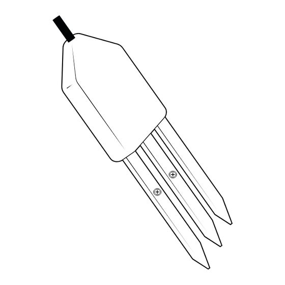
Page 15: About 5Te
The 5TE is designed to measure the water content, EC, and temperature of soil (Figure 5). The 5TE uses an oscillator running at 70 MHz to measure the dielectric permittivity of soil to determine the water content. a thermistor in thermal contact with the sensor prongs provides the soil temperature, while the screws on the surface of the sensor form a two-sensor electrical array to measure EC. -
Page 16: Theory
The 5TE uses a two-sensor array to measure the EC. The array is located on the screws of two of the 5TE prongs. 5TE EC measurements are normalized to 25 °C. See Section 4.2... -
Page 17: Converting Bulk Ec To Pore Ec
However, this is a time-consuming and labor-intensive process. σ The 5TE measures the EC of the bulk soil surrounding the sensors ( ). METER has σ conducted a considerable amount of research to determine the relationship between σ... -
Page 18: Pore Water Versus Solution Ec
SySTEM σ METER testing indicates that the above method for calculating results in good accuracy (20%) in moist soils and other growth media. in dry soils where VWC is less than about 0.10 m³/m³, the denominator of pore water conductivity equation becomes very small, σ... -
Page 19: Service
4.1.1 DIELECTRIC PERMITTIVITY METER factory calibrates each 5TE sensor to measure dielectric permittivity (ε ) accurately in the range of 1 (air) to 80 (water). The unprocessed raw values reported by the 5TE in ε standard serial communication have units of 50 . -
Page 20: Calibration In Soilless Media
METER continually develops additional calibration equations for various other growth media as opportunities arise. Contact Customer Support for the status of this ongoing research. The 5TE can accurately read VWC in virtually any porous medium if a custom calibration is performed. Contact Customer Support for more information. -
Page 21: Troubleshooting
Do not touch the screws without gloved hands and never contact the sensors with any source of oil or other nonconducting residue. 4.3 TROUBLESHOOTING if problems with the 5TE are encountered, they most likely manifest themselves in the form of incorrect or erroneous readings. Review the information in Table 1... -
Page 22: Customer Support
SERViCE Table 1 Troubleshooting the 5TE (continued) Problem Possible Solution Check for air gaps around sensor needles. These could be produced below the surface of the substrate when the needle contacts a large piece of material and pushes it out of the way or if the sensor is not Sensor reading too low inserted perfectly linearly. -
Page 23: Terms And Conditions
NOTE: For products purchased through a distributor, please contact the distributor directly for assistance. 4.5 TERMS AND CONDITIONS By using METER instruments and documentation, you agree to abide by the METER Group, inc. USa Terms and Conditions. Please refer to metergroup.com/terms-conditions... - Page 24 REFERENCES REFERENCES Hilhorst, M.a. 2000. "a Pore Water Conductivity Sensor." Soil Science Society of America Journal 64, no. 6: 1922–1925. Topp, G. Clarke, J.L. Davis, and a. Peter annan. 1980. "Electromagnetic Determination of Soil Water Content: Measurement in Coaxial Transmission Lines." Water Resources Research 16, no.3: 574–582.
-
Page 25: References 20
INDEX INDEX orientation 4 accuracy 8 particle size 2 bulk EC 8, 13–14 phone number 18, 19 pore EC 13–15 power requirements 9 cable length 9 calibration 15–16 cleaning 16 range 8 communication 7, 9 references 20 compliance 11 connecting METER data logger 5 non-METER logger 5–6 specifications 8–11... - Page 26 14575-02 1.15.2019 METER Group, Inc. USA 2365 NE Hopkins Court Pullman, WA 99163 T: +1.509.332.5600 F: +1.509.332.5158 E: info@metergroup.com W: metergroup.com METER Group AG Mettlacher Straße 8, 81379 München T: +49 89 12 66 52 0 F: +49 89 12 66 52 20 E: info@metergroup.de W: metergroup.de...
Need help?
Do you have a question about the 5TE and is the answer not in the manual?
Questions and answers