Advertisement
CP-UM-5306E
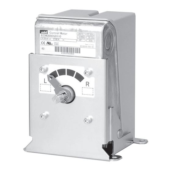
Control Motor
Model ECM3000
User's Manual
Thank you for purchasing an Azbil Corporation product.
This manual contains information for ensuring the correct
use of this product. This manual should be read by those who
design and maintain equipment that uses this product.
Be sure to keep this manual nearby for handy reference.
Please read "Terms and Conditions" from the following URL
before ordering and use.
https://www.azbil.com/products/factory/order.html
NOTICE
Be sure that the user receives this manual before the product is
used.
Copying or duplicating this user's manual in part or in whole is
forbidden. The information and specifications in this manual are
subject to change without notice.
Considerable effort has been made to ensure that this manual is
free from inaccuracies and omissions. If you should find an error or
omission, please contact the azbil Group.
In no event is Azbil Corporation liable to anyone for any indirect,
special or consequential damages as a result of using this product.
SAFETY PRECAUTIONS
Safety precautions are for ensuring safe and correct use of
this product, and for preventing injury to the operator and
other people or damage to property. You must observe these
safety precautions. Also, be sure to read and understand the
contents of this user's manual.
If this device is used in a manner not specified by the
manufacturer, its built-in protective functions may be
impaired.
Key to symbols
l
WARNING
Warnings are indicated when mishandling this prod-
uct might result in death or serious injury to the user.
CAUTION
Cautions are indicated when mishandling this prod-
uct might result in minor injury to the user, or only
physical damage to this product.
WARNING
Before doing other wiring work, connect the frame
ground terminal to ground. The ground connection
should have a resistance of 100 Ω or less. Afterwards
connect the other circuits.
Before removing, mounting, or wiring this device, be
sure to turn off the power to the device and all connected
devices. Failure to do so may cause electric shock.
Do not touch electrically charged parts such as the
power terminals. There is a risk of electric shock.
In order to use this product correctly, be sure to follow
this manual, the manuals for any associated devices
and equipment.
Installation, wiring, inspection, adjustment, maintenance,
etc., should be carried out only by trained and experi-
enced technicians who have knowledge and technical
skills related to this device and associated equipment.
Be sure to use this device correctly, within the ranges
specified in this user's manual. Otherwise device fail-
ure or malfunction could result.
Avoid installing the device where it will be subject to
conditions such as the following. Otherwise device fail-
ure could result.
• Certain chemicals, corrosive gases, or salt
• High temperatures
• Prolonged vibration
• Direct sunlight
Do not stand on this device or use it as a step.
Doing so could damage the device, and if you lose your
footing you may be injured.
Wire this device properly according to indoor wiring
standards, technical standards, etc., using the types of
wire and wiring methods specified in the user's manual.
Otherwise, device failure or malfunction could result.
The motor part of this device can reach a high tempera-
ture during operation. There is a risk of burns if the
cover is opened and the motor is touched immediately
after the power has been turned off.
While power is being supplied and during operation, do
not touch any movable part. Doing so may cause injury.
If equipment safety may be endangered by the failure
of this device, consider having a fail-safe design for the
system as a whole, with circuit breakers, duplexed con-
trollers, and limiter; or use a redundant design.
When discarding this device, dispose of it properly as
industrial waste, following local regulations.
WARNING SYMBOLS USED FOR THE PRODUCT
To reduce the risk of an electric shock. resulting in
personal injury, and to ensure safe operation of de-
vices, follow all safety notices in this document.
This symbol warns the user when there is a danger
of electric shock from accidental contact.
This symbol on the motor warns the user that there
is a danger of burns from accidental contact.
Check the following items when removing the ECM3000 from its
package:
Name
Part No.
• Upset head bolt with captive washer
395-106-25A
• label [0],[100] 83165267-001
• User's Manual CP-UM-5306JE 1 This Manual
ECM3000 control motors are designed to control various types of
industrial equipment.
There are two types of strokes: a 90° stroke for burner control and
a 160° stroke for valve control using hot and cold water, steam,
etc. There are three types of control signal inputs: relay contact,
4–20 mA DC, and potentiometer (nominal 135 Ω resistance input).
24, 100, and 200 V AC models are available. Flexible 85–264 V AC
powered models are also available for 4–20 mA DC signal input
models. The included bracket can be used for replacement of an
older Azbil Corporation motor with this one.
1
CAUTION
UNPACKING
Q'ty Remarks
4 M6 size
1 0(fully closed) and 100(fully open)
OVERVIEW
Advertisement
Table of Contents

Related Manuals for Azbil ECM3000 Series

Summary of Contents for Azbil ECM3000 Series
- Page 1 Group. In no event is Azbil Corporation liable to anyone for any indirect, system as a whole, with circuit breakers, duplexed con- special or consequential damages as a result of using this product.
- Page 2 MODEL SELECTION TABLE : Applicable —: Not applicable Rotation time Rotation Output Power Model No. Power Signal name Notes angle torque consumption 50Hz 60Hz ECM3000D01 _ _ 24 V AC Relay contacts 90° 39 s 33 s 9 VA* ON/OFF operation 12.5 N・m ...
-
Page 3: Names Of Parts
• When the motor is used with a control valve in an appli- NAMES OF PARTS cation such as fluid control, if the control valve is located Resin cover: protects the inside of the device. higher than the motor, water drops may enter the motor by running along the valve. - Page 4 If the ECM3000E is used to fully open/close the valve 24 V AC F.G. L: counterclockwise (CCW) rotation R: clockwise (CW) rotation * For details on TY9000, etc., contact the azbil Group. Azbil Corporation's l 4–20 mA input (ECM3000G) L91 pressure regulator Switch for...
-
Page 5: Inspection And Maintenance
l How to set the operating point INSPECTION AND MAINTENANCE (1) Operate the motor electrically until the output shaft travels „ Inspection Method to the desired angle that turns on the switch. Then, align the arrow on the setting dial with the mark using a flat- Item Frequency... - Page 6 „ Installation and removal l Removal (1) Remove the 2 screws. l Installation (2) Remove the terminal block. The bracket is combined with (1) Turn OFF the power. the terminal block. (2) Loosen the 3 screws and remove the cover. Keep the re- moved parts in a safe place.
-
Page 7: Specifications
20/16 s Relay contact, 50/60 Hz, without load, been conventionally used in the industry. high-speed motor model The following are Azbil Corporation’s controllers compatible with 160° stroke 69/58 s Relay contact, 50/60 Hz without load this device: SDC35/36, SDC45/46, the SDC40 series, DMC10, Network... - Page 8 × : 表示该有害物质至少在该部件的某一均质材料中的含量超出GB/T 26572规定的限量要求。 (100 % opening) Max. applied voltage 5 V DC Specifications are subject to change without notice. (11) 1-12-2 Kawana, Fujisawa Kanagawa 251-8522 Japan URL: https://www.azbil.com 1st edition: Dec. 2003 (E) © 2003–2019 Azbil Corporation. All Rights Reserved. 10th edition: July 2019 (V)
Need help?
Do you have a question about the ECM3000 Series and is the answer not in the manual?
Questions and answers