
Summary of Contents for Alpine HC Opera Signature Profiling Bed
- Page 1 Bed Installation Guide and Technical Specifications for Opera Signature Profiling Bed ® A product by Alpine HC, Azure House, Connaught Road, Kingswood, Hull. HU7 3AP 0333 222 8584 | support@alpinehc.co.uk | alpinehc.co.uk...
-
Page 2: Table Of Contents
Contents 1. Explanations of Symbols ..............2 2. Installation and Commissioning ..........3 3. Bed Operation and Maintenance ..........25 4. Troubleshooting ................29 5. Safety Instructions ................30 6. General Information ................34 7. Servicing ....................36 8. Technical Specification ..............40 9. Service Life and Disposal ..............47 10. -
Page 3: Explanations Of Symbols
1. Explanations of Symbols Read information with this symbol carefully and urgently follow instructions. This information is safety-relevant. This symbol indicates hazards due to electrical voltage. There is mortal danger! ELECTRICAL This symbol indicates general hazards. There is danger to life and health. DANGER Conformity mark in accordance with the Medical Device Directive (93/42 EEC). -
Page 4: Installation And Commissioning
2. Installation and Commissioning What’s in the box: OP011 Head/Footboard x 2 OP012 Side Rail x 4 OP041 Mattress Platform Securing Bolt* x 16 OP042 Side Skirt Fixing Bolt x 8 OP043 Side Rail Channel Fixing Bolt** x 4 OP044 Chassis Securing Bolt x 4 * Eight of these are already fitted to the Mattress Platform Backrest Section OP013... - Page 5 2. Installation and Commissioning OP014 Mattress Platform Backrest Section OP015 Mattress Platform Legrest Section N.B. Easily identifiable because it has both an actuator N.B. Easily identifiable because it only has one actuator. and the black control box. OP017 Mattress Holding OP018 Side Rail End OP022...
- Page 6 2. Installation and Commissioning Before you begin! We recommend that two people install this bed due to the weight of individual parts. Position the bed Move the bed into the centre of the room. Place the side rail and side skirt boxes to one side. Place accessories to one side Detach the following accessories: OP018 - Side Rail End Caps...
- Page 7 2. Installation and Commissioning Remove bed components from transportation bracket Loosen the thumb screws on each side of the transportation bracket and slide the head and foot boards out of the bracket. Then lift the mattress platform sections out of the transportation bracket.
- Page 8 2. Installation and Commissioning Secure actuator motor Stand the legrest section of the mattress platform (OP015) on its end with the actuator motor at the top. On the actuator securing bracket, remove the safety pin to allow the actuator to be positioned in line with the mounting bracket, then reapply the safety pin to secure the actuator in place.
- Page 9 2. Installation and Commissioning Place the backrest mattress platform on the bed chassis Lift the backrest section of the mattress platform onto the head end of the bed chassis. Ensure the backrest section is NOT placed above the height adjustment actuator/motor on the chassis! Position so that the securing bar pictured in the first image below is aligned with the u-bracket which is on the...
- Page 10 2. Installation and Commissioning Fix backrest mattress platform Now that the backrest section has been placed on the bed chassis, line up the mattress platform so the two screw holes either end align. Manually lift the backrest profiling section (not whole platform) to access the screw holes.
- Page 11 2. Installation and Commissioning Plug in actuators to raise bed Plug the height adjustment actuator, backrest actuator and handset control into the correct color-coded sections of the control box as shown below. Raise the bed Plug the bed into a mains power supply and raise the bed to a suitable working height to attach the legrest mattress platform section to the chassis.
- Page 12 2. Installation and Commissioning Connect mattress platforms and secure legrest section Lift the legrest mattress platform onto the chassis and align the metal prongs in the backrest section with the holes in the legrest section. Feed the metal prongs into the holes until the mattress platforms are joined.
- Page 13 2. Installation and Commissioning Connect remaining actuators Plug in the legrest actuator into the control box. Once completed, attach the control box cover using a standard Phillps screw driver. Signature Installation Guide and Technical Specification...
- Page 14 2. Installation and Commissioning Attach head and foot boards Lift the head/foot board so the two metal prongs either side are in line with the two holes at the end of the mattress platform. Slide into place so that the head/foot board is flush with the mattress platform.
- Page 15 2. Installation and Commissioning Fit side skirts Unpack the 2 Side Skirts (OP013) from their box. Using the Side Skirt Fixing Bolts (OP042) and the 4mm Allen key to attach the Side Skirts to the mattress platform side channels using the holes provided. Insert all the bolts before tightening fully.
- Page 16 2. Installation and Commissioning Fit side rail end caps Unpack the side rails (OP012) from their box. Lay all four side rails on the floor. Fit the plastic end caps (OP018) to both ends of the rails. The easiest way to put the end caps on is to use the bottom of the side rail as a leading edge (as pictured).
- Page 17 2. Installation and Commissioning Insert side rail runners into head board Unscrew the Side Rail Channel Fixing Bolt (OP043) on the head board and slide the side rail runners up the channel. Once in place fix the runners by replacing the bolts. Signature Installation Guide and Technical Specification...
- Page 18 2. Installation and Commissioning Fit side rails to headboard Fit the wooden side rails onto the side rail runner by sliding the fingers all the way into the wood of the side rails. The side rail runner fingers go into the top and bottom holes of the side rail.
- Page 19 2. Installation and Commissioning Complete side rail fitting Remove the Side Rail Channel Fixing Bolt (OP043) from the footboard. Attach the side rail runner to the foot end of the side rails as shown in step 16. Now slide the side rail runner into the channel and bring it up until it clicks into place at the top of the channel.
- Page 20 2. Installation and Commissioning Mattress holders Clip in place the mattress holders (OP017), 2 slats down from the top of the backrest, and 2 slats up from the bottom of the legrest. Repeat for the other side of the bed. Test functions Test the controls on the bed are working correctly, by performing the following steps:...
- Page 21 2. Installation and Commissioning Confirm compliance Measure the distance between the side rails when in the up position. This distance should be around 110mm, which is less than the maximum 120mm stipulated in the bed rail regulations. Position the bed Once the testing has been completed satisfactorily, you are ready to move the bed into the desired position.
- Page 22 2. Installation and Commissioning Installation Complete! Remove all packaging and the transportation brackets from the room, and you have successfully completed the installation! Signature Installation Guide and Technical Specification...
- Page 23 2. Installation and Commissioning Signature Installation Guide and Technical Specification...
- Page 24 2. Installation and Commissioning Construct the Patient Pole Assemble the patient pole by first fitting together the two poles by inserting the smaller end of the crooked pole into the opening in the straight pole. Secure by tightening the black thumb screw, ensuring it threads through both the hole in the straight pole and the hole in the crooked pole.
- Page 25 2. Installation and Commissioning Attach the Handle Place the loop of the webbing strap over the top of the pole and secure between the two pins. Test the triangular handle by pulling down tightly. Signature Installation Guide and Technical Specification...
-
Page 26: Bed Operation And Maintenance
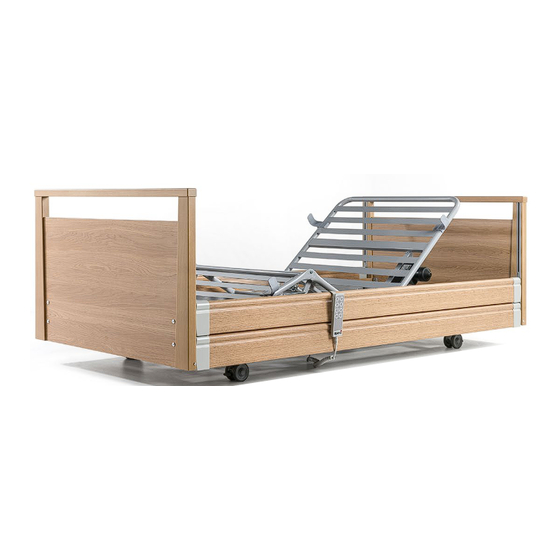
3 Bed Operation and Maintenance 3. 1 Overview 1. Height adjustment actuator 9. Foot board 2. Electrically adjustable backrest 10. Mattress holders 3. Electrically adjustable legrest 11. Side rails 4. Mechanically adjustable legrest 12. Side rail channel 5. Handset with locking key 13. - Page 27 Handset with Locking Function The motorised bed functions can be operated via the handset. All functions can be locked with the nurses’ key. Backrest adjustment up/down Handset hook Leg rest adjustment up/down Mattress Platform adjustment up/down Height adjustment, up/down Nurse key Locking device To avoid damage, the handset should always be hung up (e.g.
- Page 28 Operation of the Side Rails To use the side rails, lift the upper side rail until it locks into place in the highest position. To lower the side rails, lift the upper side rail and at the same time push the triangular release catch and lower the side rails.
- Page 29 Electric Emergency Lowering The power supply unit fitted on the bed frame is equipped with a 9V block battery, which makes it possible to make a CPR emergency lowering according to EN 60601-2-52 in the event of a power failure. Please note, however, that this is only possible once per 9V battery, as the capacity of the 9V battery is limited.
-
Page 30: Troubleshooting
4. Troubleshooting Fault Possible cause Remedy No response Mains plug not plugged Insert mains plug into mains socket. Locking function on Unlock handset. handset activated. Handset not plugged in. Insert handset plug into the correct control box* socket. Actuator motor/s not Plug actuator motor/s into plugged in. -
Page 31: Safety Instructions
When the side rails are used, the following instructions must be adhered to: • Use only approved side rails supplied as an option by Alpine HC. See suitable dimensions at section 7.1. • Only suitably instructed personnel are allowed to operate the side rails. - Page 32 Disconnect the mains plug from the socket before moving the bed, and take care to avoid dragging the mains plug across the floor when moving the bed. The mains plug must always remain accessible to enable immediate cut-off by unplugging the mains plug from the wall socket in case of emergency. The mains cable must be free and not caught up in anything, as it gets carried along when the bed height is adjusted and the mains plug may be pulled out of its socket and electric leads exposed as a result.
- Page 33 Refer to section 7.2. Any defects, damage or signs of wear must be rectified without delay. Only original spare parts from Alpine HC may be used, otherwise all guarantees or warranties will be excluded.
- Page 34 The 9V block battery is the energy store for electrical emergency lowering in the event of a power failure. The energy store is sufficient for one emergency lowering at the most and must then be replaced. If the expiry date of the battery has elapsed then it must be replaced immediately.
-
Page 35: General Information
Clean and disinfect the care bed before using it for the first time. Please note that the various safety instructions must be observed. Alpine HC beds bear the CE mark and meet all safety and functionality requirements. These care beds were tested according to the international standards which contain the safety requirements for medical products. - Page 36 Intended Use This care bed is intended for accommodating patients or occupants (with body mass ≥150 cm to max. 165 kg) in residential homes, nursing homes and the domestic environment. The bed may only be used under the conditions for use described in this Instruction Manual.
-
Page 37: Servicing
General Regulations The care bed must only be used for the purpose intended. When setting up, operating, and using the care bed, respect the regulations in your country, the general recognised rules of technology, the occupational health and safety, and accident prevention regulations. - Page 38 Item Instruction for testing Comment Is the general condition OK? Are the type plates for the bed and the motors legible? Is the Instruction Manual available to staff? Is the use one for which it was intended and is it safe? No surface damage or corrosion? Mechanical components and welded joints without faults?
- Page 39 Item Instruction for testing Comment Yes No Height of side guards above the mattress at least 220 mm? Have castors including locking brake been tested for safe functioning? Mains cable, connecting cables and plugs without damage? Fixture available for safe transportation of mains plug? Strain relief of the mains cable and handset securely attached?
- Page 40 Checking the Initial Fault Safety To check the safety equipment, proceed as follows: The switching positions I and II are testing settings used only to check the safety during the annual inspection, or after repair work, or each time bed is put into service again. •...
-
Page 41: Technical Specification
8. Technical Specification 8. 1 Technical Data (Mechanical) Safe working load (max. admissible load): 220kg Individual loads of the safe working load (advisory): Max. Weight of patient 185kg Mattress 20kg Accessories 15kg Total 220kg Safe load, patient’s lifting pole 80kg Max. - Page 42 Technical Data (Electrical) Power supply unit (LIMOSS) Control unit MC220 + SMPS MC125 Voltage rating 230/240V Frequency rating 50-60 Hz Type of current AC ~ Nominal consumption during 70 Watt operation Nominal consumption in idle state 0.5 Watt Nominal operating time/nominal 2 Min.
- Page 43 Technical Data (Environmental) Temperature range during operation +10°C to + 40°C Temperature range for storage/transport -10°C to + 60°C Humidity of the air 30% to 75% rel. Air pressure 795 – 1060 hPa Weights of the Individual Components Mattress platform - head section 24kg Mattress platform –...
- Page 44 Information about Electromagnetic Emissions Guidance and manufacturer’s declaration - electromagnetic emissions The care bed is intended for use in the electromagnetic environment specified below. The customer or user of the care bed should ensure that it is used in such an environment.
- Page 45 Guidance and Manufacturer’s Declarations - Electromagnetic Interference Immunity The care bed is intended for use in the electromagnetic environment specified below. The customer or user of the care bed should ensure that it is used in such an environment. Interference Immunity IEC 60601 Test Compliance level Electromagnetic...
- Page 46 Guidance and Manufacturer’s Declarations – Non-life-support devices Electromagnetic Interference Immunity The care bed is intended for use in the electromagnetic environment specified below. The customer or user of the care bed should ensure that it is used in such an environment. Interference IEC 60601 Compliance...
- Page 47 Recommended working clearances between portable and mobile RF communications equipment and the care bed The care bed is intended for use in an electromagnetic environment in which radiated RF disturbances are controlled. The customer or user of the care bed can help to prevent electromagnetic interference by maintaining a minimum distance between portable and mobile RF communications equipment (transmitters) and the care bed as recommended below, according to the maximum output power of the communication device.
-
Page 48: Service Life And Disposal
11. 1 Warranty Terms 10.1.1 Subject to the terms and conditions set out below, Alpine HC Ltd agrees to repair or replace the product within the United Kingdom at its own cost, and any Opera accessory supplied with it, purchased by you from Alpine HC Ltd, in circumstances where the product does not perform in accordance with Alpine HC Ltd’s specifications during the warranty period of 3 years, commencing on... - Page 49 11. 2.5 If Alpine HC Ltd is unable to repair or replace the product, the customer will be provided with credit for Alpine HC Ltd product or may be refunded the price of the product (at Alpine HC Ltd’s election). This credit or refund will be for the amount of the purchase price of the product excluding the associated delivery cost.
- Page 50 Alpine HC Ltd’s aggregate liability in respect of all claims under the warranty shall not exceed the original purchase price of the product or, at Alpine HC Ltd’s option, the replacement of the product with a like or similar product.
-
Page 51: Declaration Of Conformity
Date: 01/01/2018 Revision: CE Declaration of Conformity In accordance to annex VII of the 93/42 EEC for medical devices from September 2007 Alpine HC Limited t/a Opera® Azure House, Connaught Road Kingswood Hull, HU7 3AP United Kingdom declare on our own responsibility that the following group of products or products: Opera®... - Page 52 A product by Alpine HC, Azure House, Connaught Road, Kingswood, Hull. HU7 3AP 0333 222 8584 | support@alpinehc.co.uk | alpinehc.co.uk...
Need help?
Do you have a question about the Opera Signature Profiling Bed and is the answer not in the manual?
Questions and answers