Table of Contents
Advertisement
Quick Links
Download this manual
See also:
Owner's Manual
Advertisement
Table of Contents

Related Manuals for Cal Flame BBQ09843B

Summary of Contents for Cal Flame BBQ09843B
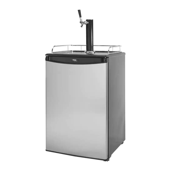
- Page 1 BEER KEG REFRIGERATOR Model:BBQ09843B...
-
Page 2: Safety Precautions
INSTRUCTION MANUAL F OR Beer Keg Refrigerator SAFETY PRECAUTIONS Read all of the instructions before using this appliance. When using this appliance, always exercise basic safety precautions, including the following: 1. Use this appliance only for its intended purpose as described in this operation manual. 2. - Page 3 70° F). Secure fasten with a chain in an upright position when storing. 7. Always ventilate and leave the area immediately if CO2 leakage has occurred! 8. There are two safety devices in the pressure system in the form of a valve. One safety feature is on the bottle.
- Page 4 SAVE THESE INSTRUCTIONS FOR FUTURE USE Page...
-
Page 5: Proper Location
DANGER! Risk of child entrapment! Before throwing away your old appliance, remove the door so that children may not easily become trapped inside. • Take off the doors. • Leave the shelves or other accessories in place so that children may not easily become trapped inside. (Note: If the refrigerator has been placed in a horizontal or tilted position for any period of time, please wait at least 24 hours before plugging the unit in.) PROPER LOCATION... -
Page 6: Installing The Beer Tap
end of the unit, with the unlocked casters fasted on the rear end. handle inStaLLinG the beer taP Follow the steps below to install the beer tap. beer There are notches on the bottom of the draft arm Dispenser assembly that line up with grooves inside the opening on tower the top of the beer keg fridge. Align the draft arm with the opening on the top of the unit, then place inside and twist... - Page 7 INSTALLING THE REGULATOR AND THE CO2 CYLINDER Follow these steps to safely install the regulator and cylinder. You must read and understand the following procedures for the cylinders before installation. NOTE: Your cylinder has DOT (USA Department of Transportation) approval, however the cylinder has been shipped empty to avoid any possible accidents during...
- Page 8 3. Attach the line end of the tube to the hose connection on the tap. Next, secure the tube by using the remaining self-locking plastic snap-on clamp to ensure that there are no leaks. Secure the clamp tightly with pliers (Fig. 3 - below). 4. Make sure the beer tower faucet is in the closed (handle pointing straight back) position before connecting the tap to the keg. To secure the tank connection, pull the tapping handle out and push down until it locks into position. Listen for the “click” of the pull handle when it shifts into the final downward position (Fig. 4 - below). This will open the beer and gas valves. The keg is now tapped.
-
Page 9: Cleaning And Maintenance
OPERATING YOUR BEER KEG FRIDGE Dispensing Beer Follow the steps below to dispense beer. 1. Make sure that the beer keg fridge is plugged in properly to a 115V, 60Hz,1.1Amps grounded AC power outlet. 2. place the drip tray under beer faucet to avoid messes from excess beer. 3. -
Page 10: Special Safety Information
SPeciaL Safety information important Safety message for Draft beer Dispensing Your beer keg fridge system has two safety devices already provided in the pressure line. The coupler for this beer keg fridge is compatible with the ¼ Pony Keg sized barrel and the ½ Barrel full size (US Kegs). While the beer keg fridge can hold both the 5 gallon Cornelius Keg and the 5 gallon D System Keg, should you decided to run either one of these 5 gallon kegs, you may need to obtain a alternate keg connector. Safety devices should be installed in the following places: a. On or directly downstream from the regulator. b. On the tapping device. c. In-line in the pressure system note: Locations A and B noted above are preferable. If possible, they should be built into the regulator and tapping device so that they cannot be removed or by-passed. - Page 11 Illustration E Illustration F Page.
-
Page 12: Technical Data
TECHNICAL DATA 115V nput 115V~ 60Hz Rated 1.1 A Rated Current Capacity 170 L / 6.1 CUFT INSTRUCTIONS ON ENVIRONMENT PROTECTION Do not dispose of this product in the usual household garbage at the end of its life cycle; hand it over at a collection point for the recycling of electrical and electronic appliances.
Need help?
Do you have a question about the BBQ09843B and is the answer not in the manual?
Questions and answers