Table of Contents
Advertisement
Advertisement
Table of Contents

Summary of Contents for Zenitel Vingtor Stentofon 1008015000
- Page 1 Configuration Manual SIP Master Stations TECHNICAL MANUAL A100K11211...
- Page 2 About this Document Document Scope This document describes the configuration of the STENTOFON SIP Master Stations. Publication Log Rev. Date Author Status 19.1.2012 published 9.6.2017 VS format, SIP server Related Documentation For further information, refer to the following documentation: Doc. no. Documentation A100K10788 IP Master Station Installation &...
-
Page 3: Table Of Contents
Contents 1 Introduction ........................4 1.1 IP Desktop Master Station ..................4 1.2 IP OR Master Station ....................5 1.3 IP Flush Master Station .....................5 1.4 IP Dual Display Station .....................5 2 SIP Configuration ......................6 2.1 Configuration Via Station Keypad ................6 2.2 SIP Station Web Interface ..................7 2.3 Station Main Settings ....................8 2.4 SIP Settings ......................8 2.5 Audio Settings ...................... -
Page 4: Introduction
Introduction SIP (Session Initiation Protocol) is the de facto standard for IP telephony. The STENTOFON SIP intercom stations are specially built for easy integration with any iPBX system. The STENTOFON SIP Stations are custom-made IP intercom stations that can integrate with any iPBX system. iPBX (SIP domain) SIP phone IP Network... -
Page 5: Ip Or Master Station
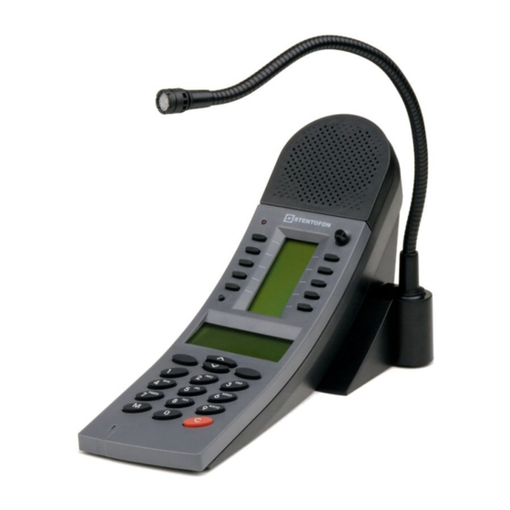
IP OR Master Station ● item no. 1008015000 The IP Operating Room (OR) Master Station is an advanced intercom station intended for use in operating theatres and clean rooms. The chemical resistant and anti-bacterial front plate is completely flat and sealed to minimize bacteria accumulation. -
Page 6: Sip Configuration
SIP Configuration There are two ways of configuring the IP Master Station for SIP: ● Using the station keypad ● Using a web browser Configuration Via Station Keypad When the IP Master Station is not registered with the SIP server, an offline menu is displayed. The offline menu can be used to configure the station and is navigated with the 4 buttons below the display. -
Page 7: Sip Station Web Interface
SIP Station Web Interface The SIP Station features an embedded web server, which allows users to log in via a standard web browser. At commissioning, the SIP Station needs to be configured to make it possible for the SIP Station to register in the iPBX system. To do this, your PC and the IP station have to be connected together via a PoE switch using network cables: ●... -
Page 8: Station Main Settings
Station Main Settings ● Click Station Main > Main Settings to access the page for configuring station mode and IP parameters. Station Mode ● Select the Use SIP radio-button IP Settings ● DHCP – Use this option if the SIP Station shall receive IP Settings from a DHCP server. - Page 9 Account Settings Display Name - Enter a name that will be shown on the display at the remote party. Directory Number (SIP ID) - This is the identification of the station in the SIP domain, i.e. the phone number for the station. This parameter is mandatory. Enter the SIP ID in integers according to the SIP account on the SIP domain server.
- Page 10 - Check the checkbox to enable this function and enter the delay in seconds in the field for Auto Answer Delay. The default delay setting is 0 and the maximum is 30 seconds. Disable Disconnect By Button - This disables disconnect with the speed dial during and when setting up a conversation.
-
Page 11: Audio Settings
Audio Settings Click Station Configuration > Audio Settings Speaker Volume - Select the volume level in the range 0 to 7 from the dropdown menu. The default setting is 5. Noise Reduction Level - Level 0 means that the function is disabled - Level 1 gives a maximum noise reduction of 0.2 dB - Level 2 gives a maximum noise reduction of 6.2 dB - Level 3 gives a maximum noise reduction of 12.2 dB... -
Page 12: Direct Access Key Settings
Direct Access Key Settings ● Click Station Configuration > Direct Access Key Settings to access the page for configuring DAKs. Direct Access Key Settings Direct Access Key 1 - Direct Access Key 4 Enter the numbers to call in the Value field. L The Desktop and Dual Display master stations have 10 Direct Access Keys and do not have the 3 Input Buttons described below. Input Button 1 This is the SIP ID for the extension to be called when call button no. -
Page 13: Snmp Settings
Direct Access Key Settings (In Call) - Select input buttons 1 - 3 for direct access calls while in conversation. - Options are: End Call, Do Nothing, Send Text, Send DTMF L Pin connections for the three input buttons are located on the P4 connector. See Section 4: Station Board Connections for more information. - Page 14 Allowed Network - This is used, together with the network mask, to determine the allowed network for reading the MIB on the station. - The IP address is entered in regular dot notation, e.g. 10.5.2.100. For example with an allowed network 10.5.2.0 and a network mask of 24, any station with an IP address in the range 10.5.2.0 to 10.5.2.255 can access the MIB.
-
Page 15: Automatic Configuration Using Tftp
Sound Test Success - If enabled, the station will send an SNMP trap when a sound test is successful. Input Button Pressed - If enabled, the station will send an SNMP trap when an input button is pressed. Input Button Released - If enabled, the station will send an SNMP trap when an input button is released. -
Page 16: Advanced Configuration Options
4. Under Configuration Updates select the radio button for Automatic 5. Either select the radio button for From DHCP or enter the IP address of the TFTP server (your PC IP address) 6. Under Automatic Update Interval enter the interval in minutes for checking updates. - Page 17 Clicking the Apply settings button will apply the chosen settings. With the exception of a restart, the saved settings will not come into effect until Apply settings is clicked. Enable VLAN This option determines whether the switch uses 802.1Q or not. If this is enabled, the switch is VLAN aware.
-
Page 18: 2.9.2 Network Access Control
The VLANs that the ports are members of are listed under the Membership Info column. The table also lists the ports that keep the VLAN tag when sending egress packets; this is shown under the Egress Tagging Info column. The VLAN table can accommodate a maximum of 63 VLANs. - Page 19 Fake username: The fake user name sent outside of encrypted tunnel with TTLS with PAP and PEAP with MSCHAPV2. The user name is encrypted. If TTLS with PAP or PEAP with MSCHAPV2 is chosen, a certificate must be uploaded to the station by clicking Browse. The certificate must either be in Privacy Enhanced Mail (PEM) or Distinguished Encoding Rules (DER) format, and it must be named certificate.pem.
-
Page 20: Software Upgrade
TFTP Server Program Both upgrade methods require that an TFTP Server is available and that the latest software image file has been downloaded from Zenitel’s support website (AlphaWiki). During the upload process, the IP station will connect to the TFTP Server and download the software. The TFTP Server program must already be installed on your PC/server with a defined IP address. -
Page 21: Automatic Software Upgrade
5. Enter the name of the software Image file (include bin file extension) 6. Enter the CRC checksum (found in the text file from the downloaded software package) 7. Click Save settings to store the data The station will now try to contact the TFTP server. If the connection cannot be established or the file tftp_test.txt is missing from the directory, the message TFTP_CONN_ERROR is displayed. - Page 22 3. Select Advanced Configuration > Updates 4. Under Configuration Updates select the radio button for Automatic - Automatic Configuration Updates has to be enabled 5. Either select the radio button for From DHCP or enter the IP address of the TFTP server (your PC IP address) 6.
-
Page 23: Station Board Connections
Station Board Connections AUX IP LED3 LED6 LED4 MICROPHONE Figure 5 Station Board Connections RJ45 LAN connector for 10/100 Mbit Ethernet connection. The station can be powered from this connection if the line supports Power over Ethernet (PoE). The connector has two LEDs in front where the right (R) LED indicates Ethernet speed and the left (L) LED verifies Ethernet link and traffic. - Page 24 Pin 5/6 Connect 24 VDC for station power if PoE is not used. Pin 6 is positive. KEY1 6-pin plug-on screw terminal for external connections. KEY2 Pin 1/4 Input 1 KEY3 Pin 2/4 Input 2 Pin 3/4 Input 3 Pin 5/6 Station LED for call message info.
- Page 25 Handset: Pin 1 Mic+ Pin 2 Spk+ Pin 3 Spk- (0 V) Pin 4 Mic- Pin 5 Hook-switch (must be connected to pin 3 with a switch) Pin 6 PTT (May not be supported by SW) Headset: Pin 7 Mic+ Pin 8 Spk+ Pin 9...
-
Page 26: Station Indication Leds
Station Indication LEDs Station LED LED4 - Red 5mm LED on board rear side, also seen through front plate. Flashing at 1 second intervals - Station has no connection to the SIP server. Possible reasons: - No connection to Ethernet - Wrong SIP server IP address configured - Invalid IP address - No gateway or wrong gateway to the SIP server... -
Page 27: Lan Leds
LAN LEDs These LEDs are on the LAN (P1) and AUX (P2) RJ45 ports. Left LED Steady light: Ethernet connection OK Flashing: Ethernet traffic No light: No Ethernet connection Right LED Light: 100 Mbit Ethernet connection No light: 10 Mbit Ethernet connection A100K11211 SIP Master Stations Configuration... -
Page 28: Restoring Factory Defaults
Restoring Factory Defaults An IP Master Station may have to be reset to its original factory default settings if, for instance, the password to the web server is forgotten. ● Connect 24 VDC to P3 5/6 to power up the station. Stations with display - Main menu - Station info -- >... -
Page 29: Configuration File Parameters
Configuration File Parameters Remote Provisioning using TFTP An IP station may be set up to automatically poll configuration from a TFTP server. The IP address of this TFTP server can be obtained using DHCP procedures or be manually configured. The IP station will first try to download the global configuration file: ipst_config.cfg Then the IP station will download a device specific configuration file: ipst_config_01_02_03_04_05_06.cfg... -
Page 30: Sip Parameters
SIP Parameters nick_name Required: No. Defaults to sip_id. Description: The nickname for the station can be used to assign a logical name to the station. For example, a station belonging to James may be assigned the nickname “James” or “James’ station”. Values: Text string. -
Page 31: Call Parameters
sip_outbound_proxy_port Required: If proxy server is defined. Default is 5060. Description: The UDP port on the SIP proxy server. Values: Integer. register_interval Required: No. Defaults to 600 seconds. Description: This parameter specifies how often the station will register, and reregister, in the SIP domain. This parameter will affect the time it takes to discover that a connection to a SIP domain is lost. - Page 32 speeddial_3_ip Required: No Description: If desired, an IP address can be configured as a backup for speeddial_3. If the station has no connection to any of the configured SIP domains, it can call directly to this IP address. Values: IP address given in regular dot notation, e.g. 10.5.2.100 speaker_volume Required: No.
-
Page 33: Snmp Parameters
Values: Integer. 0 ≤ activate_relay_event ≤ 9 activate_relay_duration Required: No. Defaults to 60. Description: This parameter sets the duration for the relay activation in seconds. Values: 0 ≤ activate_relay_duration ≤ 240. 0 means that the relay stays open. SNMP Parameters trap_receiver Required: No. - Page 34 enable_ipsStarted Required: No. Defaults to 1. Description: If enabled, the station will send an SNMP trap when the station application is started. Values: 0 = disabled, 1 = enabled. enable_sipRegistered Required: No. Defaults to 1. Description: If enabled, the station will send an SNMP trap when successfully registered in the SIP domain.
-
Page 35: Example Configuration Files
Example Configuration Files 7.6.1 Device Specific Configuration File [general] auto_update_interval=10 auto_update_image_type=A100G80200.01_10_1_2.bin auto_update_image_crc=C1466499 [sip] nick_name=Testname sip_id=1003 sip_domain=10.5.2.209 sip_domain2=10.5.2.138 auth_user=1003 auth_pwd=1003pass sip_outbound_proxy=10.5.2.138 sip_outbound_proxy_port=5060 register_interval=600 [call] speeddial_1=1000 speeddial_1_ip=10.5.2.200 speeddial_2=1004 speeddial_2_ip=10.5.2.201 speeddial_3=1005 speeddial_3_ip=10.5.2.202 speaker_volume=4 mic_sensitivity=5 rtp_timeout=60 remote_controlled_volume_override_mode=1 auto_answer_mode=1 auto_answer_delay=10 disable_disconnect_by_button=1 activate_relay_event=* activate_relay_duration=10 [snmp] trap_receiver=10.5.2.219 network=10.5.2.0 network_mask=24 community=public enable_v1=1 enable_v2c=1 enable_ipsStarted=1 enable_sipRegistered=1 enable_sipRegisterFailed=1... -
Page 36: 7.6.2 Global Configuration File
7.6.2 Global Configuration File The global configuration file has the same parameters as the device specific file except that the four parameters below will be ignored. Hence, it is recommended that the following parameters not be used in the global configuration file. nick_name sip_id auth_user... - Page 37 A100K11211 SIP Master Stations Configuration...
- Page 38 A100K11211 Zenitel and its subsidiaries assume no responsibility for any errors that may appear in this publication, or for damages arising from the information therein. VINGTOR-STENTOFON products are developed and marketed by Zenitel. The company’s Quality Assurance System is certified to meet the requirements in NS-EN ISO 9001. Zenitel reserves the right to modify designs and alter specifications without notice.